Note: Descriptions are shown in the official language in which they were submitted.
CA 02954799 2017-01-11
WO 2016/041650 PCT/EP2015/064230
SOLENOID VALVE
The invention relates to a solenoid valve comprising a housing, an inlet, an
outlet, main valve means located between said inlet and said outlet, said
main valve means comprising a main valve element, pilot valve means
adjusting a pressure difference over said main valve element and having a
pilot valve element, a coil, a yoke arrangement magnetically linked to said
coil, and armature means for moving said pilot valve element.
Such a solenoid valve is known, for example, from DE 20 2005 013 233 U1.
The use of a pilot valve has the advantage that only the pilot valve element
has to be actuated to control the function of the main valve means. The
forces needed for moving the pilot valve element are much smaller than the
forces needed for moving the main valve element. Therefore, a pilot control
solenoid valve can be used to control fluids under high pressure, for example
carbon dioxide, without dramatically increasing the coil and yoke
arrangement.
In some cases it is required that a solenoid valve has a large opening stroke,
i. e. the solenoid valve has a low flow resistance in fully open state. This
means that the main valve means has to be opened to a rather large extend
to that the main valve element must be able to perform a large opening
stroke. Consequently, the pilot valve element must be able to perform a
similar large openings stroke. When the pilot valve is closed, the armature
means has the largest distance to the yoke arrangement so that the magnetic
forces which can attract the armature means are quite low. Therefore, when
a large opening stroke is required, the coil and yoke arrangement must be
increased to a considerable size to generate the necessary magnetic
attraction forces.
Such a solenoid valve can be, for example, used in a multiejector. In this
case it is required to generate maximum velocity of the controlled gas at the
CA 02954799 2017-01-11
WO 2016/041650
PCT/EP2015/064230
-2 -
so called motive nozzle. This is done by minimizing the pressure losses. One
contribution to the low pressure loss comes from a large diameter or large
opening when the valve is open. A large diameter here means that the main
valve element needs to move a significant part of, as a rule, at least 1/4 of
the
diameter of an outlet bore. This means that there are low magnetic forces
available because the magnetic forces vary over the distance from the yoke
arrangement to the armature means.
Furthermore, when the solenoid valve is used in a CO2 system the pressure
difference is significantly higher than for other refrigerants. In a CO2
system
pressure difference of at least 50 bar is possible and can be significantly
higher, for example 90 bar.
This means that the valve has to open with relative weak magnetic forces
while being able to cope with a significantly higher pressure difference.
The object underlying the invention is to achieve a large opening stroke
without unduly increasing the coil and yoke arrangement.
This object is solved with a solenoid valve as described above in that said
armature means comprise a first part attractable by said yoke means to
perform an opening stroke, and a second part carrying said pilot valve
element, wherein said first part is movable relative to said second part in a
first section of said opening stroke and is dragging said second part in a
second section of said opening stroke following said first section, wherein an
opening spring is located between said first part and said second part, said
opening spring acting on said second part in opening direction.
In such a solenoid valve the coil and yoke arrangement generate a magnetic
force which must be sufficient to attract the first part of the armature only.
The first part of the armature can be moved over a first section of the
opening
CA 02954799 2017-01-11
WO 2016/041650
PCT/EP2015/064230
-3-
stroke without the necessity of moving the second part. The first part of the
armature means is accelerated by the magnetic forces and has, therefore, at
the end of the first section of the opening stroke a certain speed and
consequently a certain kinetic energy. Furthermore, the magnetic forces have
also increased since the air gap has decreased. At the end of the first
section
of the opening stroke the first part comes in contact with the second part of
the armature which then is moved under the action of the first part. For the
movement of the second part of the armature the increased magnetic forces
plus the kinetic energy of the first part can be used. The second part carries
the pilot valve element, meaning that the pilot valve element can also be part
of the second part. The combined energy is sufficient to pre-lift the pilot
valve
element from the pilot valve seat. This initial movement of the pilot valve
element usually requires the largest forces. As soon as the pilot valve
element has been lifted off the pilot valve seat, the forces tending to close
the
pilot valve means or keeping the pilot valve means closed decrease so that
the second part can be moved further together with the first part in an
opening direction. When the pilot valve element has been lifted off the pilot
valve seat under the action of the first part, the opening spring is slightly
compressed. The opening spring now moves the second part relative to the
.. first part further in opening direction thus increasing a distance between
the
pilot valve element and the pilot valve seat. This is possible due to the low
force from the differential pressure at the pilot valve element. This low
force
is due to the relative large distance between the pilot valve element and the
pilot valve seat or pilot orifice after the pre-lift. When the pilot orifice
is open,
the main valve element moves and opens the main valve means. This
opening can occur in a rather short time period so that the solenoid valve can
be actuated with a rather high speed. The opening of the pilot valve now is
divided in three sections of movement. In the first section only the first
part
moves. In the second section the first part moves together with the second
part and the pilot valve element. In the third section the first part has been
stopped and the pilot valve element together with the second part moves
CA 02954799 2017-01-11
WO 2016/041650
PCT/EP2015/064230
- 4 -
under the action of the opening spring. During the first section, when the
first
part is moved alone, this first part builds up kinetic energy and moves closer
to the yoke arrangement whereby the magnetic forces increase significantly
since the air gap decreases. Both elements contribute to the pre-lifting of
the
pilot valve element against the significant pressure difference over the pilot
valve element. At the end of the third movement the second part rests
against the yoke arrangement. The third movement is achieved by utilizing
the spring forces created by the compression of the opening spring during
the second movement.
In a preferred embodiment said pilot valve means has a pilot orifice and the
length of said second section is in the range of 0,5 to 1,5 times the diameter
of said pilot orifice. The second part of the armature is moved at an end of
the opening stroke only, when the first part has enough kinetic energy. Since
it is only necessary to pre-lift the pilot valve element the small movement of
the second part of the armature at this moment is sufficient. Less than 0,5
means that the pressure difference becomes too big. More than 1,5 means
that the magnetic forces become too small.
Preferably a closing spring is arranged between said first part and said yoke
arrangement, said closing spring being compressed during said opening
stroke. The closing spring is used at a later stage when the main valve is to
be closed.
Preferably said opening spring is stronger than said. closing spring. In other
words, the spring constant of the opening spring is typically larger than the
spring constant of the closing spring. This takes into account that the
closing
spring is compressed during the opening stroke to a slightly larger extend.
CA 02954799 2017-01-11
WO 2016/041650
PCT/EP2015/064230
-5-
Preferably said second part is located inside said first part. This leads to
rather simple construction. The armature can still be handled as a single
piece simplifying assembling of the solenoid valve.
In this case it is preferred that said first part comprises a hollow first
sleeve
and a hollow second sleeve which are connected to each other to form a
space in which said second part is accommodated. The two sleeves can for
example be fixed to each other by screwing, by using a glue or by soldering
or they can be joined by a press-fit connection. The use of hollow sleeves
facilitates the guiding of the second part within the first part.
Preferably said first sleeve has a bore at a side facing said yoke
arrangement, said bore ending at a step supporting said closing spring. The
closing spring rests against the step and against the yoke arrangement. The
bore is helpful in guiding the spring so that the spring keeps its position in
any case.
Preferably said second part comprises a stem protruding through said bore.
The stem in said bore is used for guiding the second part within said first
part.
Preferably said stem is longer than said first sleeve. This feature can be
used
to improve the closing process of the solenoid valve. The magnetic sticking
force is overcome by the force of the opening spring. Since the stem is longer
than the first sleeve, the opening spring pushes the first part in a direction
towards the pilot valve seat. Once the first parts abuts the second part the
opening spring does no longer contribute to further movement of the first part
and further movement of the first and second parts is achieved by the closing
spring. The magnetic sticking is reduced by a large amount, for example,
90 %, once an air gap between the yoke arrangement and the armature is
CA 02954799 2017-01-11
WO 2016/041650
PCT/EP2015/064230
-6-
established and therefore the closing spring can close the valve even if it is
weaker.
Preferably said housing comprises a stop for said main valve element in
opening direction, said second part of said armature being retracted behind
said stop at the end of said opening stroke. This is a protection for the
pilot
valve element avoiding high forces on the pilot valve element in the fully
open
state of the main valve means.
The invention relates as well to the use of a solenoid valve as described
above in a CO2 refrigeration system. The solenoid valve is in particular well
suited to operate even if high pressure differences act over the pilot valve
means.
A preferred embodiment of the invention now is described in more detail with
reference to the drawing, wherein:
Fig. 1 is a sectional view of a solenoid valve in close condition,
Fig. 2 is a sectional view of the solenoid valve at a beginning of the
opening of a pilot valve means,
Fig. 3 is a sectional view of said solenoid valve with the pilot valve
means fully open,
Fig. 4 is a sectional view of said solenoid valve with the main valve
means fully open,
Fig. 5 is a sectional view of said solenoid valve at the beginning of
closing of the pilot valve means, and
- 7 -
Fig. 6 is a sectional view of said solenoid valve showing the closing
of
the main valve means.
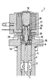
Fig. 1 shows a solenoid valve 1 having a housing 2. The housing 2
comprises an inlet 3 and an outlet 4. The solenoid valve 1 can, for example,
be used for controlling a fluid under high pressure like carbon dioxide.
The control of such a fluid is performed by main valve means 5 having a
main valve element 6 and a main valve seat 7.
The main valve element 6 has the form of a piston having a channel 8
running in lengthwise direction through the complete valve element 6. One
end of this channel 8 opens into the main valve seat 7 (in closed condition)
or
is directed into the main valve seat 7 (in open condition, c. f. figures 4 to
6).
The other end of the channel 8 forms a pilot orifice 9. This pilot orifice 9
can
also be named "pilot valve seat".
A small gap 10 between the main valve element 6 and the housing 2 is
unavoidable and in the present case intended so that a fluid pressure from
the inlet 3 can act on both front faces 11, 12 of the main valve element 6,
i.e.
in a pressure space 13 on a side of the main valve element 6 opposite to said
main valve seat 7. The area of the front face 11 surrounding the main valve
seat 7 is smaller than the area of the opposite front face 12 so that the main
valve element 6 is held against the main valve seat 7 by the resulting force
difference and the main valve means 5 are closed.
Furthermore, the solenoid valve 1 comprises pilot valve means 14. The pilot
valve means 14 comprise a pilot valve element 15 cooperating with the pilot
orifice 9, I. e. closing the pilot orifice 9 (fig. 1 and 6) or opening it
(fig. 2 - 5).
Movement of the pilot valve element 15 is performed by an armature 16
which will be described later.
CA 2954799 2021-09-22
CA 02954799 2017-01-11
WO 2016/041650
PCT/EP2015/064230
-8-
The solenoid valve 1 comprises a coil 17 and a yoke arrangement 18 (only
partly shown). When the coil 17 is supplied with electric current, the yoke
arrangement 18 which is magnetically linked to the coil 17 generates a
magnetic force acting on the armature 16.
The armature 16 comprises a first part 19 and a second part 20. The first part
19 is formed of a first sleeve 21 and a second sleeve 22. Both sleeves 21,22
are hollow. They are connected to each other in a connection area 23. They
can, for example, be joined by a press-fit connection or connected by means
of a pair of threadings, they can be glued together or brazed together or
connected to each other in any other way. The first part 19 is made from a
magnetizable material, whereas there are no similar requirements to the
second part 20.
The two sleeves 21, 22 together form a space 24 in which the second part 20
of the armature is accommodated. The second part 20 of the armature 16
carries the pilot valve element 15.
The first sleeve 21 comprises a bore 25 through which a stem 26 of the
second part is guided. Furthermore, the bore 25 forms a step 27. A closing
spring 28 rests against this step 27. The other end of the closing spring 28
rests against the yoke arrangement 18. When the first part 19 is moved in a
direction towards the yoke arrangement 18, the closing spring 28 is
compressed.
An opening spring 29 is arranged in the space 24 within the first part 19 as
well. This opening spring 29 acts between the first part 19 and the second
part 20 and presses the second part 20 against the first sleeve 21.
CA 02954799 2017-01-11
WO 2016/041650
PCT/EP2015/064230
- 9 -
The state shown in fig. 1 is the closed state of the solenoid valve 1. The
closing spring 28 acts on the whole armature 16 in a direction towards the
pilot orifice 9. The pilot valve element 15 rests against the pilot orifice 9
and
closes the pilot valve means 14. In this state there is no current in coil 17.
Fig. 2 shows the situation in which the coil 17 is supplied with current.
Therefore, magnetic forces are generated in the yoke arrangement 18
attracting the first part 19 of the armature 16.
All elements are designated with the same reference numerals in all figures.
As can be seen in fig. 2 the first part 19 of the armature 16 has been moved
relative to the second part 20 of the armature.
The first part 19 has been moved over an opening stroke, i. e. from the
position shown in fig. 1 in which the first part 19 has the largest distance
to
the yoke arrangement 18 to a position shown in fig. 2 in which the first part
19 has come to rest against the yoke arrangement 18.
.. This opening stroke has some sections. In a first section the first part 19
can
be moved relative to the second part 20 of the armature without moving the
second part 20 of the armature 16. In a second section of the opening stroke
the first part 19 has come in contact with a step 30 at the lower end of the
second part 20 and pulls or drags the second part 20 upon further movement
of the first part 19.
During movement of the first part 19, the closing spring 28 and the opening
spring 29 are compressed.
At the end of the first section, the first part 19 of the armature has already
a
certain speed and correspondingly a certain kinetic energy. This kinetic
CA 02954799 2017-01-11
WO 2016/041650
PCT/EP2015/064230
-10-
energy can be used to move the second part 20 of the armature 16 as well.
This movement can be rather small, for example less than 1 mm. In general,
the second section of the opening stroke has a length in the range of 0,5 to
1,5 times the diameter of the pilot orifice 9. Less than 0,5 means that the
pressure difference becomes too big. More than 1,5 means that the magnetic
forces become too small. The movement of the second part 20 is sufficient
when the pilot valve element 15 is just lifted off the pilot orifice 9 so that
fluid
out of the pressure space 13 can start to escape out of the pressure space
13 thereby lowering the pressure in the pressure space 13. This state can be
termed as "pre-lift".
As shown in fig. 2, the first part 19 has come in contact with the yoke
arrangement 18 thereby compressing the closing spring. Furthermore, the
opening spring 29 between the first part 19 and the second part 20 is
compressed as well.
As shown in fig. 3, the opening spring 29 moves the second part 20 further in
opening direction, i. e. in a direction towards the yoke arrangement 18 until
the stem 26 comes in contact with the yoke arrangement 18 as well. This is a
third section of movement. Consequently, the pilot valve element 15 is
moved further away from the pilot orifice 9. This movement is possible due to
the low force from the differential pressure at the pilot valve element 15.
This
low force is due to the relative large distance between the pilot valve
element
15 and the pilot orifice 9 after pre-lift. Fig. 3 shows the fully open
condition of
the pilot valve means 14.
When the pilot valve means 14 are open the pressure in the pressure space
13 decreases and consequently the pressure acting on the lower front face
11 generates a force higher than the pressure acting on the opposite front
face 12 of the main valve element 6. The main valve element 6 moves away
from the main valve seat 7 and opens the main valve means 5.
CA 02954799 2017-01-11
WO 2016/041650
PCT/EP2015/064230
-11-
As can be seen in fig. 4, the housing 2 has a stop 31 for the movement of the
main valve means 6 in opening direction. The pilot valve element 15 is
retracted behind this stop 31 when the second part 20 of the armature 16 has
come in contact with the yoke arrangement 18. Therefore, high forces acting
on the pilot valve element 15 by the main valve element 6 can be reliably
avoided.
Fig. 4 shows the solenoid valve 1 in fully open condition. This condition
remains as long as current is supplied to coil 17. The supply of current to
coil
17 can be made over an electric connection 32 schematically shown.
When the supply of current to coil 17 is stopped, no magnetic forces are
generated in the yoke arrangement 18.
When the current is switched off, the closing process starts. The magnetic
sticking force is overcome by the force of the opening spring 29. Since the
stem 26 is longer than the first sleeve 21, the opening spring 29 pushes the
first part 19 away from the yoke arrangement 18 in a direction towards the
pilot valve orifice 9. Once the first part 19 abuts the second part 20 the
opening spring 29 does no longer contribute to further movement of the first
part (as shown in fig. 5) and further movement of the first and second part
19,
20 is achieved by the weaker closing spring 28. The magnetic sticking is
reduced by, for example, 90 % once an air gap between the yoke
arrangement 18 and the top of the armature 16 is established and therefore
the closing spring 28 can close the pilot valve even when it is weaker than
the opening spring 29.
In fig. 5 the armature 16 has moved away a bit from the yoke arrangement
18. However, in fig. 5 the pilot valve means 15 has still a distance from the
pilot orifice 9 so that the pilot valve means 14 are not yet closed.
CA 02954799 2017-01-11
WO 2016/041650 PCT/EP2015/064230
-12-
Fig. 6 shows the situation in which the armature 16 has been moved far
enough in a direction towards the main valve element 6 to close the pilot
valve means 14, i. e. the pilot valve element 15 has closed the pilot orifice
9.
In this situation the pressure space 13 has no outlet through which fluid
arriving from the inlet 3 can escape. The pressure acting on the upper front
face 12, I. e. the front face facing the yoke arrangement 18 acts on the main
valve element 6 in a direction towards the main valve seat 7. The same
pressure acts on the opposite front face 11, however, on a smaller area since
the valve seat 7 covers part of the front face 11. In a region of the front
face
covered by the main valve seat 7, there is a lower pressure.
The difference of forces over the main valve element 6 moves the main valve
element 6 in a direction towards the main valve seat 7 so that finally the
main
valve element 6 comes to rest the main valve seat 7 and the main valve
means 5 close, as shown in fig. 1. The closure spring 28 does also
contribute.