Language selection

Search

Patent 2954817 Summary

Third-party information liability

Some of the information on this Web page has been provided by external sources. The Government of Canada is not responsible for the accuracy, reliability or currency of the information supplied by external sources. Users wishing to rely upon this information should consult directly with the source of the information. Content provided by external sources is not subject to official languages, privacy and accessibility requirements.

Claims and Abstract availability

Any discrepancies in the text and image of the Claims and Abstract are due to differing posting times. Text of the Claims and Abstract are posted:

  • At the time the application is open to public inspection;
  • At the time of issue of the patent (grant).
(12) Patent: (11) CA 2954817
(54) English Title: VOLATILE SUBSTANCE EVAPORATOR DEVICE
(54) French Title: DISPOSITIF EVAPORATEUR DE SUBSTANCES VOLATILES
Status: Granted
Bibliographic Data
(51) International Patent Classification (IPC):
  • A61L 9/03 (2006.01)
  • A61L 9/02 (2006.01)
(72) Inventors :
  • LLORENTE ALONSO, JOAQUIM (Spain)
  • MAYOR SANS, FERNANDO (Spain)
  • RUIZ ESPANOL, JULIO, CESAR (Spain)
(73) Owners :
  • ZOBELE ESPANA, S.A. (Spain)
(71) Applicants :
  • ZOBELE ESPANA, S.A. (Spain)
(74) Agent: OYEN WIGGS GREEN & MUTALA LLP
(74) Associate agent:
(45) Issued: 2023-03-14
(86) PCT Filing Date: 2015-07-10
(87) Open to Public Inspection: 2016-01-14
Examination requested: 2020-06-19
Availability of licence: N/A
(25) Language of filing: English

Patent Cooperation Treaty (PCT): Yes
(86) PCT Filing Number: PCT/ES2015/070543
(87) International Publication Number: WO2016/005648
(85) National Entry: 2017-01-11

(30) Application Priority Data:
Application No. Country/Territory Date
P201431049 Spain 2014-07-11

Abstracts

English Abstract

The volatile substance-evaporator device comprises a source of heat (1) and a refill (2) that includes said volatile substances, and is characterized in that said source of heat is a flame (1) that heats a transmission element+ (3), which heats said refill (2) in order to evaporate the volatile substances. The result thereof is that the volatile substances evaporate properly, without the need to use batteries or a similar power source, simply by the use of a flame, for example in the form of a candle, the financial cost thereof being very low.


French Abstract

Le dispositif évaporateur de substances volatiles selon l'invention comprend une source de chaleur (1) et un élément de recharge (2) qui comporte lesdites substances volatiles, et est caractérisé en ce que ladite source de chaleur est une flamme (1) qui chauffe un élément de transmission (3), lequel chauffe ledit élément de recharge (2) pour évaporer les substances volatiles. Les substances volatiles sont ainsi évaporées correctement sans avoir à utiliser de batteries ni de source d'alimentation similaire, simplement au moyen d'une flamme, par exemple sous forme d'une bougie, son coût étant par conséquent très réduit.

Claims

Note: Claims are shown in the official language in which they were submitted.

6
CLAIMS
1. Volatile substance evaporator device comprising: a heat source (1) and a
refill (2)
including said volatile substances, wherein said heat source is a flame (1)
that heats
a transmission element (3) which heats said refill (2) for evaporating the
volatile
substances; wherein said transmission element (3) further comprises a first
portion
to be heated by said flame (1) and a second portion to heat said refill (2);
wherein
said first portion and said second portion are substantially perpendicular to
one
another; and a casing (4) externally covering said transmission element (3),
wherein
said casing (4) is disposed between said transmission element (3) and said
refill (2);
wherein said casing (4) comprises a hole (5) in an area between said
transmission
element (3) and said refill (2), said hole (5) being adjacent said
transmission element
(3) on a first side and adjacent said refill (2) on a second side that is
opposite the
first side; and wherein a portion of said casing (4) extends over the first
portion of
the transmission element (3) and the heat source (1).
2. Volatile substance evaporator device according to claim 1, wherein said
transmission element is a plate (3) made of a heat transmitting material.
3. Volatile substance evaporator device according to claim 1 or claim 2,
wherein
said second portion is wider than said first portion.
4. Volatile substance evaporator device according to claim 2, wherein said
heat
transmitting material is metal or ceramic.
5. Volatile substance evaporator device according to claim 2 or claim 4,
wherein
said heat transmitting material is aluminum, steel or copper.
6. Volatile substance evaporator device according to claim 1, wherein said
hole (5)
is covered by means of a protective grille (6).
7. Volatile substance evaporator device according to claim 1, comprising a
convection groove (7) to cause an airflow consisting of volatile substances.
8. Volatile substance evaporator device according to claim 1, wherein said
refill (2)

7
comprises an outer ring (8) provided with a projection (9).
9. Volatile substance evaporator device according to claim 8, wherein said
outer ring
(8) and said projection (9) are made of a thermally insulating material.
10. Volatile substance evaporator device according to claim 1, claim 8 or
claim 9,
wherein said refill (2) is a thermoformed container with a membrane.

Description

Note: Descriptions are shown in the official language in which they were submitted.


CA 02954817 2017-01-11
1
VOLATILE SUBSTANCE EVAPORATOR DEVICE
The present invention relates to a volatile substance evaporator device
comprising
a heat emitter evaporating volatile substances contained in a refill.
Background of the Invention
Conventional volatile substance evaporator devices comprise a heat emitter,
for
example, an electrical resistance, that heats a refill, for example, an
impregnated
tablet or a container. Furthermore, they also sometimes require the use of
fans or
other electromechanical elements to force the airflow for proper volatile
substance
diffusion.
The presence of electrical resistances, fans and other electromechanical
elements
for evaporating and diffusing volatile substances require the device to
include
power supply means.
The main drawback of conventional volatile substance evaporator devices is
that
they usually use replaceable batteries as said power supply means, from which
they obtain the energy required for operation.
Batteries are not well accepted by consumers due to their financial impact,
their
dependency, and the added ecological impact entailed by using same.
There is therefore an obvious need for an evaporator device that does not
require
the use of batteries, allowing the use of an economical and eco-friendly power

source.
Description of the Invention
The evaporator device of the invention solves the mentioned drawbacks, having
other advantages that will be described below.
The volatile substance evaporator device according to the present invention
comprises a heat source evaporating volatile substances of a refill.

CA 02954817 2017-01-11
2
The volatile substance evaporator device according to the present invention
comprises a heat source and a refill including said volatile substances, and
it is
characterized in that said heat source is a flame that heats a transmission
element
which heats said refill for evaporating the volatile substances.
According to a preferred embodiment, said transmission element is a plate made

of a heat transmitting material, and said plate preferably comprises a first
portion
to be heated by said flame and a second portion to heat said refill.
According to the preferred embodiment, said first portion and said second
portion
are substantially perpendicular to one another, and said second portion is
preferably wider than said first portion.
Furthermore, said heat transmitting material is metal or ceramic, for example,
aluminum, steel or copper.
Advantageously, the volatile substance evaporator device according to the
present
invention comprises a casing externally covering said transmission element,
said
casing comprising a hole in the area between the transmission element and the
refill.
To prevent a user of the device from getting burned, said hole is covered by
means of a protective grille.
The volatile substance evaporator device according to the present invention
also
advantageously comprises a convection groove to cause an airflow consisting of

volatile substances.
Advantageously, said refill comprises an outer ring provided with a
projection,
which are made of a thermally insulating material, which allows removing the
refill
easily without the risk of a user getting burned.
According to a preferred embodiment, said refill is a thermoformed container
with
a membrane.

CA 02954817 2017-01-11
3
The volatile substance evaporator device according to the present invention
results in volatile substances evaporating properly without having to use
batteries
or a similar power source, simply using a flame, for example in the form of a
candle, the financial cost thereof being very low.
Brief Description of the Drawings
To better understand what has been set forth, drawings schematically depicting
a
practical embodiment only by way of a non-limiting example are attached.
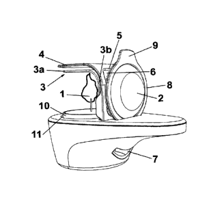
Figure 1 is a front perspective view of the volatile substance evaporator
device
according to the present invention; and
Figure 2 is a rear perspective view of the volatile substance evaporator
device
according to the present invention.
Description of a Preferred Embodiment
The evaporator device according to the present invention comprises a heat
source
1, such as a flame of a candle 10 provided with a wick, acting on a refill 2
including
the volatile substances to be evaporated.
Said candle 10 is placed inside a housing 11 and can be replaced with a new
candle as many times needed.
The evaporator device also comprises a transmission element 3 transmitting
heat
from the flame 1 to the refill 2, such that said heat will cause the volatile
substances from the refill 2 to evaporate.
According to the embodiment depicted in the drawings, this transmission
element
3 is a plate made of a heat transmitting material, for example metal or
ceramic,
such as aluminum, steel or copper, and defines a first portion 3a placed in
the
proximity of said flame 1 and a second portion 3b placed next to or in contact
with
said refill 2.

CA 02954817 2017-01-11
4
For example, the first portion 3a is placed at a distance between 0 and 100 mm

with respect to the flame 1 and the second portion 3b is placed at a distance
between 0 and 15 mm from the refill 2.
It is calculated that the first portion 3a can reach a temperature between 100
C
and 150 C, whereas the second portion 3b can reach a temperature between
70 C and 90 C.
According to the depicted embodiment, said portions 3a and 3b of the
transmission element 3 are substantially perpendicular to one another, as can
be
seen in the drawings, and said first portion 3a is narrower than said second
portion
3b. In this manner, according to the depicted embodiment the first portion 3a
is
substantially horizontal and the second portion 3b is substantially vertical
in the
normal position of use of the evaporating device.
To make it easier for the transmission element 3 to maintain a high
temperature
and in order to protect the user, the evaporating device also comprises a
casing 4
placed on the outer part of said transmission element 3, as can be seen in the

drawings.
To allow the transmission element 3 to heat the refill 2, said casing 4
comprises a
hole 5 in the area between the transmission element 3 and the refill 2. To
prevent
a user from directly contacting the transmission element 3 in this area, said
hole 5
is covered with a grille 6, such that the temperature of the grille will be
between
35 and 80 C.
The evaporating device according to the present invention also preferably
comprises a convection groove 7 to cause an airflow consisting of volatile
substances.
The refill 2 is in turn preferably a thermoformed container provided with a
membrane to make it easier to evaporate the volatile substances, and comprises

an outer ring 8 provided with a projection 9. This projection 9 allows the
user to
remove the refill 2 easily without any risk of getting burned, since the ring
8 and
the projection 9 are made of a temperature-resistant material.

CA 02954817 2017-01-11
It is very simple to put the evaporating device according to the present
invention in
operation since it simply requires placing a candle 10 in its housing 11 and
lighting
it. The heat generated by the flame 1 of said candle 10 will be transmitted to
the
5 refill 2 previously placed in position through the transmission element
3, the heat
of which will cause the volatile substances to evaporate without the need for
electrical power supply means, such as batteries or the like. When the candle
10
has burned out, it must simply be replaced with a new one.
Although reference has been made to a specific embodiment of the invention, it
is
obvious for a person skilled in the art that the evaporator device described
is
susceptible to a number of variations and modifications, and that all the
mentioned
details can be replaced with other technically equivalent details without
departing
from the scope of protection defined by the attached claims.

Representative Drawing
A single figure which represents the drawing illustrating the invention.
Administrative Status

For a clearer understanding of the status of the application/patent presented on this page, the site Disclaimer , as well as the definitions for Patent , Administrative Status , Maintenance Fee  and Payment History  should be consulted.

Administrative Status

Title Date
Forecasted Issue Date 2023-03-14
(86) PCT Filing Date 2015-07-10
(87) PCT Publication Date 2016-01-14
(85) National Entry 2017-01-11
Examination Requested 2020-06-19
(45) Issued 2023-03-14

Abandonment History

There is no abandonment history.

Maintenance Fee

Last Payment of $210.51 was received on 2023-07-07


 Upcoming maintenance fee amounts

Description Date Amount
Next Payment if standard fee 2024-07-10 $277.00
Next Payment if small entity fee 2024-07-10 $100.00

Note : If the full payment has not been received on or before the date indicated, a further fee may be required which may be one of the following

  • the reinstatement fee;
  • the late payment fee; or
  • additional fee to reverse deemed expiry.

Patent fees are adjusted on the 1st of January every year. The amounts above are the current amounts if received by December 31 of the current year.
Please refer to the CIPO Patent Fees web page to see all current fee amounts.

Payment History

Fee Type Anniversary Year Due Date Amount Paid Paid Date
Application Fee $400.00 2017-01-11
Maintenance Fee - Application - New Act 2 2017-07-10 $100.00 2017-01-11
Maintenance Fee - Application - New Act 3 2018-07-10 $100.00 2018-07-09
Maintenance Fee - Application - New Act 4 2019-07-10 $100.00 2019-07-04
Request for Examination 2020-07-20 $800.00 2020-06-19
Maintenance Fee - Application - New Act 5 2020-07-10 $200.00 2020-07-10
Maintenance Fee - Application - New Act 6 2021-07-12 $204.00 2021-07-05
Maintenance Fee - Application - New Act 7 2022-07-11 $203.59 2022-07-05
Final Fee 2022-12-30 $306.00 2022-12-21
Maintenance Fee - Patent - New Act 8 2023-07-10 $210.51 2023-07-07
Owners on Record

Note: Records showing the ownership history in alphabetical order.

Current Owners on Record
ZOBELE ESPANA, S.A.
Past Owners on Record
None
Past Owners that do not appear in the "Owners on Record" listing will appear in other documentation within the application.
Documents

To view selected files, please enter reCAPTCHA code :


To view images, click a link in the Document Description column. To download the documents, select one or more checkboxes in the first column and then click the "Download Selected in PDF format (Zip Archive)" or the "Download Selected as Single PDF" button.

List of published and non-published patent-specific documents on the CPD .

If you have any difficulty accessing content, you can call the Client Service Centre at 1-866-997-1936 or send them an e-mail at CIPO Client Service Centre.


Document
Description 
Date
(yyyy-mm-dd) 
Number of pages   Size of Image (KB) 
Request for Examination 2020-06-19 4 108
Examiner Requisition 2021-07-23 6 241
Amendment 2021-11-23 11 427
Claims 2021-11-23 2 73
Examiner Requisition 2021-12-23 3 172
Amendment 2022-04-22 9 278
Claims 2022-04-22 2 64
Final Fee 2022-12-21 4 106
Representative Drawing 2023-02-14 1 11
Cover Page 2023-02-14 1 43
Electronic Grant Certificate 2023-03-14 1 2,527
Abstract 2017-01-11 1 13
Claims 2017-01-11 2 49
Drawings 2017-01-11 1 32
Description 2017-01-11 5 175
Representative Drawing 2017-01-11 1 23
Representative Drawing 2017-02-06 1 14
Cover Page 2017-02-06 1 46
International Search Report 2017-01-11 4 186
Amendment - Abstract 2017-01-11 2 87
National Entry Request 2017-01-11 4 123