Language selection

Search

Patent 2954853 Summary

Third-party information liability

Some of the information on this Web page has been provided by external sources. The Government of Canada is not responsible for the accuracy, reliability or currency of the information supplied by external sources. Users wishing to rely upon this information should consult directly with the source of the information. Content provided by external sources is not subject to official languages, privacy and accessibility requirements.

Claims and Abstract availability

Any discrepancies in the text and image of the Claims and Abstract are due to differing posting times. Text of the Claims and Abstract are posted:

  • At the time the application is open to public inspection;
  • At the time of issue of the patent (grant).
(12) Patent: (11) CA 2954853
(54) English Title: DEVICE FOR EVAPORATING VOLATILE SUBSTANCES
(54) French Title: DISPOSITIF D'EVAPORATION DE SUBSTANCES VOLATILES
Status: Granted
Bibliographic Data
(51) International Patent Classification (IPC):
  • A61L 9/02 (2006.01)
  • A01M 1/20 (2006.01)
  • A61L 9/03 (2006.01)
(72) Inventors :
  • DOYLE, DOMINIC (Spain)
  • GARCIA FABREGAS, RUBEN (Spain)
  • LUQUE VERA, SERGIO (Spain)
(73) Owners :
  • ZOBELE ESPANA, S.A. (Spain)
(71) Applicants :
  • ZOBELE ESPANA, S.A. (Spain)
(74) Agent: BENOIT & COTE INC.
(74) Associate agent:
(45) Issued: 2022-08-09
(86) PCT Filing Date: 2015-07-10
(87) Open to Public Inspection: 2016-01-14
Examination requested: 2020-06-12
Availability of licence: N/A
(25) Language of filing: English

Patent Cooperation Treaty (PCT): Yes
(86) PCT Filing Number: PCT/ES2015/070542
(87) International Publication Number: WO2016/005647
(85) National Entry: 2017-01-11

(30) Application Priority Data:
Application No. Country/Territory Date
P201431047 Spain 2014-07-11

Abstracts

English Abstract

The invention relates to a device for evaporating volatile substances, which includes a heat source (5) that evaporates volatile substances from a refill (2), a heat detector (4), which can detect the heat from said heat source (5), and indicating means (7) connected to said heat detector (4), which emit an indication when the heat detector (4) detects the heat from said heat source (5), and is characterised in that said heat detector (4) is placed above said heat source (5). The invention allows the indicating means to activate practically simultaneously with the placement of the heat emitter.


French Abstract

L'invention concerne un dispositif d'évaporation de substances volatiles comprenant une source de chaleur (5) qui évapore les substances volatiles d'une recharge (2), un détecteur de chaleur (4), qui peut détecter la chaleur provenant de cette source de chaleur (5), et des moyens indicateurs (7) reliés à ce détecteur de chaleur (4), qui émettent une indication lorsque le détecteur de chaleur (4) détecte la chaleur provenant de cette source de chaleur (5), et qui est caractérisé en ce que le détecteur de chaleur (4) se situe sur la source de chaleur (5). Ce dispositif permet aux moyens indicateurs de s'activer presque simultanément au placement de l'émetteur de chaleur.

Claims

Note: Claims are shown in the official language in which they were submitted.

CLAIMS
1. A device for evaporating volatile substances comprising a heat source
(5) for
evaporating volatile substances from a refill (2), a heat detector (4) which
can detect the
heat from said heat source (5), and indicating means (7) connected to said
heat detector
(4) emitting an indication when the heat detector (4) detects the heat from
said heat
source (5), characterized in that said heat detector (4) is mounted on a
generally
horizontal fixed cantilevered structure (6) such that said heat detector (4)
is fixedly
positioned above said heat source (5).
2. The device for evaporating volatile substances according to claim 1,
wherein the
heat source (5) is exposed to the environment.
3. The device for evaporating volatile substances according to claim 1,
wherein said
heat detector (4) is a thermistor.
4. The device for evaporating volatile substances according to claim 1,
wherein said
refill is a candle (2) provided with a wick (3) and said heat source is a
flame (5).
5. The device for evaporating volatile substances according to claim 1,
wherein said
indicating means comprise at least one light emitter (7).
6. The device for evaporating volatile substances according to claim 1,
wherein said
heat detector (4) and said indicating means (7) are connected to one or more
batteries
(8).
7. The device for evaporating volatile substances according to claim 1,
wherein said
heat detector (4) and said indicating means (7) are connected to a
microprocessor, such
that said indicating means (7) are activated when the microprocessor receives
a signal
from the heat detector (4) and determines an increase in heat of at least 1 C.
per second.

8. A device for evaporating volatile substances, the device comprising: a
housing (1)
having a first area for receiving a refill (2); a fixed cantilevered structure
(6) extending
generally horizontally from the housing (1); a heat detector (4) mounted on
said fixed
structure (6); and an indicating means (7) in communication with the heat
detector (4),
wherein the refill (2) comprises a volatile substance, wherein the volatile
substance of the
refill (2) evaporates upon being heated by a heat source (5) associated with
the refill (2),
and wherein said fixed structure (6) extends over at least a portion of the
first area of said
housing such that said heat detector (4) is fixedly positioned above the heat
source (5)
when the refill (2) is received by the first area of said housing (1).
9. The device of claim 8, wherein the fixed cantilevered structure is
generally parallel
with the first area of the housing.
10. The device of claim 9, wherein the heat detector (4) is positioned at a
distal end of
the cantilevered structure, the distal end of the cantilevered structure being
positioned
directly above the heat source when the refill is received by the first area
of said housing.
11. The device of claim 10, wherein the heat source (5) is exposed to the
environment
while the refill (2) is received by the first area of said housing (1).
12. The device of claim 8, wherein the heat source (5) is exposed to the
environment
while the refill (2) is received by the first area of said housing (1).
13. The device of claim 8, wherein the first area is generally horizontal.
14. The device of claim 8, wherein the housing comprises a generally
vertical portion
extending between said cantilevered structure and said first area of said
housing.
15. The device of claim 1, wherein the refill is configured to rest upon a
first area of the
device, said fixed cantilevered structure being generally parallel with said
first area.
6

16. The device of claim 1, wherein the refill is configured to rest upon a
first area of the
device, the first area being generally horizontal.
17. The device of claim 1, wherein the refill is configured to rest upon a
first area of the
device, the device comprising a generally vertical portion extending between
said
cantilevered structure and said first area.
7

Description

Note: Descriptions are shown in the official language in which they were submitted.


CA 02954853 2017-01-11
P4054CA00
DEVICE FOR EVAPORATING VOLATILE SUBSTANCES
The present invention relates to a device for evaporating volatile substances
comprising a heat emitter evaporating volatile substances contained in a
refill.
Background of the Invention
Devices containing candles which, when lit, detect flame and activate a set of

lights are well known on the market. Generally, these devices act by means of
a
light detector and sometimes by means of a heat detector.
Lights in devices of this type allow users to check that the evaporating
device is in
operation by simply looking at it.
In known evaporating devices, the position of this sensor is below the
position of
the candle. In defining the mentioned configuration, particularly if they use
heat
detectors, there is a drawback resulting from the thermal inertia of the
system.
These devices work by activating the lights once a specific temperature is
reached
in the heat detector. This means that the consumer must wait for a few minutes
after lighting the candle in order to see how the set of lights lights up.
There is therefore a need for an evaporating device in which the indications
are
activated almost immediately when a candle is lit.
Description of the Invention
The evaporating device of the invention solves the mentioned drawbacks, having

other advantages that will be described below.
The device for evaporating volatile substances according to the present
invention
comprises a heat source for evaporating volatile substances from a refill, a
heat
detector which can detect the heat from said heat source, and indicating means

connected to said heat detector emitting an indication when the heat detector
detects the heat from said heat source, and it is characterized in that said
heat
1

CA 02954853 2017-01-11
P4054CA00
detector is placed above said heat source.
For example, the heat detector is placed at a distance between 5 mm and 20 mm
from the heat source.
Advantageously, said heat detector is arranged in a cantilevered portion
placed
above said heat source.
According to a preferred embodiment, said heat detector is a thermistor, said
refill
is a candle and said heat source is a flame.
Furthermore, said indicating means preferably comprise at least one light
emitter,
such as one or more light emitting diodes (LEDs), or a sound emitter, or the
like.
Furthermore, said heat detector and said indicating means are advantageously
connected to one or more batteries.
According to a preferred embodiment, said heat detector and said indicating
means are connected to a microprocessor, such that said indicating means are
activated or emit an indication when the microprocessor receives a signal from
the
heat detector and determines an increase in heat of at least 1 C per second.
The device for evaporating volatile substances according to the present
invention
allows the indicating means to be activated virtually in a simultaneous manner
with
the placement of the heat emitter, i.e., upon lighting the flame of the
candle,
according to the preferred embodiment. This is achieved as a result of the
proximity of the heat detector with respect to said heat emitter.
Brief Description of the Drawings
To better understand what has been set forth, drawings schematically depicting
a
practical embodiment only by way of a non-limiting example are attached.
Figure 1 is a perspective view of the device for evaporating volatile
substances
according to the present invention; and
2

CA 02954853 2017-01-11
P4054CA00
Figure 2 is an elevational view of the device for evaporating volatile
substances
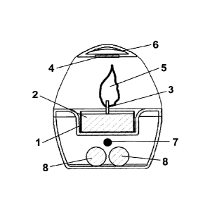
according to the present invention sectioned.
Description of a Preferred Embodiment
The evaporating device according to the present invention comprises a housing
1
for a refill, for example, a candle 2 provided with a wick 3, and a heat
detector 4,
for example, a thermistor.
This heat detector 4 is located in an elevated position right above a heat
source 5,
for example, a flame burning from the wick 3 of said candle 2. According to
the
depicted embodiment, said heat detector 4 is placed in a cantilevered portion
6 of
the device, as can be seen in the drawings. This position is suitable to be
able to
detect heat from the flame.
For example, the heat detector 4 is placed at a distance between 5 mm and 20
mm from the heat source 5.
Furthermore, the evaporating device according to the present invention also
comprises indicating means, for example, at least one light emitter 7, such as
one
or more light emitting diodes (LEDs) emitting light of one or more colors,
allowing
the user to see whether or not the heat source 5 is active by simply looking
at it.
It must be indicated that said indicating means could also be sound emitting
means such as a loudspeaker that plays a melody.
According to the depicted embodiment, said heat detector 4 and said LED 7 are
connected to a microprocessor (not depicted in the drawings), such that said
LED
7 lights up when the microprocessor receives a signal from the heat detector 4
and
an increase in heat of at least 1 C per second is determined.
If the microprocessor determines an increase in temperature less than 1 C per
second, it will then send a signal to the LED 7 for it to shut off.
Preferably, the at least one light emitter 7 is powered by means of one or
more
3

CA 02954853 2017-01-11
P4054CA00
batteries 8, although it could also be connected to the electric current or
any
suitable power source.
Obviously, the material of the device according to the present invention is
suitable
for withstanding high temperatures and being arranged close to a flame.
Furthermore, if desired, it can be a transparent or translucent material.
Although reference has been made to a specific embodiment of the invention, it
is
obvious for a person skilled in the art that the evaporating device described
is
susceptible to a number of variations and modifications, and that all the
mentioned
details can be replaced with other technically equivalent details without
departing
from the scope of protection defined by the attached claims.
4

Representative Drawing
A single figure which represents the drawing illustrating the invention.
Administrative Status

For a clearer understanding of the status of the application/patent presented on this page, the site Disclaimer , as well as the definitions for Patent , Administrative Status , Maintenance Fee  and Payment History  should be consulted.

Administrative Status

Title Date
Forecasted Issue Date 2022-08-09
(86) PCT Filing Date 2015-07-10
(87) PCT Publication Date 2016-01-14
(85) National Entry 2017-01-11
Examination Requested 2020-06-12
(45) Issued 2022-08-09

Abandonment History

There is no abandonment history.

Maintenance Fee

Last Payment of $210.51 was received on 2023-07-07


 Upcoming maintenance fee amounts

Description Date Amount
Next Payment if standard fee 2024-07-10 $277.00
Next Payment if small entity fee 2024-07-10 $100.00

Note : If the full payment has not been received on or before the date indicated, a further fee may be required which may be one of the following

  • the reinstatement fee;
  • the late payment fee; or
  • additional fee to reverse deemed expiry.

Patent fees are adjusted on the 1st of January every year. The amounts above are the current amounts if received by December 31 of the current year.
Please refer to the CIPO Patent Fees web page to see all current fee amounts.

Payment History

Fee Type Anniversary Year Due Date Amount Paid Paid Date
Application Fee $400.00 2017-01-11
Maintenance Fee - Application - New Act 2 2017-07-10 $100.00 2017-07-04
Maintenance Fee - Application - New Act 3 2018-07-10 $100.00 2018-07-05
Maintenance Fee - Application - New Act 4 2019-07-10 $100.00 2019-07-09
Registration of a document - section 124 $100.00 2019-09-06
Request for Examination 2020-07-10 $800.00 2020-06-12
Maintenance Fee - Application - New Act 5 2020-07-10 $200.00 2020-07-10
Maintenance Fee - Application - New Act 6 2021-07-12 $204.00 2021-07-05
Final Fee 2022-06-08 $305.39 2022-05-24
Maintenance Fee - Application - New Act 7 2022-07-11 $203.59 2022-07-05
Maintenance Fee - Patent - New Act 8 2023-07-10 $210.51 2023-07-07
Owners on Record

Note: Records showing the ownership history in alphabetical order.

Current Owners on Record
ZOBELE ESPANA, S.A.
Past Owners on Record
None
Past Owners that do not appear in the "Owners on Record" listing will appear in other documentation within the application.
Documents

To view selected files, please enter reCAPTCHA code :


To view images, click a link in the Document Description column. To download the documents, select one or more checkboxes in the first column and then click the "Download Selected in PDF format (Zip Archive)" or the "Download Selected as Single PDF" button.

List of published and non-published patent-specific documents on the CPD .

If you have any difficulty accessing content, you can call the Client Service Centre at 1-866-997-1936 or send them an e-mail at CIPO Client Service Centre.


Document
Description 
Date
(yyyy-mm-dd) 
Number of pages   Size of Image (KB) 
Request for Examination 2020-06-12 4 165
Change to the Method of Correspondence 2020-06-12 4 165
Request for Examination 2020-10-09 9 345
Examiner Requisition 2021-07-15 5 210
Amendment 2021-11-15 9 309
Claims 2021-11-15 3 95
Final Fee 2022-05-24 4 150
Representative Drawing 2022-07-13 1 11
Cover Page 2022-07-13 1 45
Electronic Grant Certificate 2022-08-09 1 2,527
Abstract 2017-01-11 1 15
Claims 2017-01-11 1 35
Drawings 2017-01-11 1 30
Description 2017-01-11 4 134
Representative Drawing 2017-01-11 1 27
Representative Drawing 2017-02-06 1 18
Cover Page 2017-02-06 1 50
International Search Report 2017-01-11 6 196
Amendment - Abstract 2017-01-11 2 94
National Entry Request 2017-01-11 5 197