Note: Descriptions are shown in the official language in which they were submitted.
,
,
81802458
ENHANCED DORSAL HORN STIMULATION USING MULTIPLE
ELECTRICAL FIELDS
CLAIM OF PRIORITY
[0001] This application claims the benefit of priority under 35 U.S.C.
119(e)
of U.S. Provisional Patent Application Serial Number 62/028,643, filed on
July 24, 2014.
FIELD OF THE INVENTION
[0002] The present invention relates to implantable medical systems, and
more particularly, to systems and methods for stimulating tissue.
BACKGROUND OF THE INVENTION
[0003] Implantable neurostimulation systems have proven therapeutic in a
wide variety of diseases and disorders. For example, Spinal Cord
Stimulation (SCS) techniques, which directly stimulate the spinal cord tissue
of the patient, have long been accepted as a therapeutic modality for the
treatment of chronic neuropathic pain syndromes, and the application of
spinal cord stimulation has expanded to include additional applications, such
as angina pectoralis, peripheral vascular disease, and incontinence, among
others. Spinal cord stimulation is also a promising option for patients
suffering from motor disorders, such as Parkinson's Disease, Dystonia and
essential tremor.
[0004] SCS systems typically include one or more electrode carrying
stimulation leads, which are implanted at the desired stimulation site, and a
neurostimulator (e.g., an implantable pulse generator (IPG)) implanted
1
CA 2954855 2018-04-27
CA 02954855 2017-01-10
WO 2016/014624
PCT/US2015/041469
remotely from the stimulation site, but coupled either directly to the
neurostimulation lead(s) or indirectly to the neurostimulation lead(s) via a
lead extension.
[0005] Electrical stimulation energy may be delivered from the IPG to the
electrodes in the form of an electrical pulsed waveform. Thus, electrical
pulses can be delivered from the IPG to the neurostimulation leads to
stimulate the spinal cord tissue and provide the desired efficacious therapy
to the patient. The configuration of electrodes used to deliver electrical
pulses to the targeted spinal cord tissue constitutes an electrode
configuration, with the electrodes capable of being selectively programmed
to act as anodes (positive), cathodes (negative), or left off (zero). In other
words, an electrode configuration represents the polarity being positive,
negative, or zero. Other parameters that may be controlled or varied include
the amplitude, pulse width, and rate (or frequency) of the electrical pulses
provided through the electrode array. Each electrode configuration, along
with the electrical pulse parameters, can be referred to as a "stimulation
parameter set."
[0006] The SCS system may further comprise a handheld patient
programmer in the form of a remote control (RC) to remotely instruct the IPG
to generate electrical stimulation pulses in accordance with selected
stimulation parameters. Typically, the stimulation parameters programmed
into the IPG can be adjusted by manipulating controls on the RC to modify
the electrical stimulation provided by the IPG system to the patient. Thus, in
accordance with the stimulation parameters programmed by the RC,
electrical pulses can be delivered from the IPG to the stimulation
electrode(s) to stimulate or activate a volume of tissue in accordance with a
2
CA 02954855 2017-01-10
WO 2016/014624
PCT/US2015/041469
set of stimulation parameters and provide the desired efficacious therapy to
the patient. The best stimulus parameter set will typically be one that
delivers stimulation energy to the volume of tissue that must be stimulated in
order to provide the therapeutic benefit (e.g., treatment of pain), while
minimizing the volume of non-target tissue that is stimulated.
[0007] However, the number of electrodes available combined with the
ability to generate a variety of complex electrical pulses, presents a huge
selection of stimulation parameter sets to the clinician or patient. For
example, if the SCS system to be programmed has an array of sixteen
electrodes, millions of stimulation parameter sets may be available for
programming into the SCS system. Today, SCS systems may have up to
thirty-two electrodes, thereby exponentially increasing the number of
stimulation parameters sets available for programming.
[0008] To facilitate such selection, the clinician generally programs the IPG
through a computerized programming system; for example, a clinician's
programmer (CP). The CP can be a self-contained hardware/software
system, or can be defined predominantly by software running on a standard
personal computer (PC). The CP may actively control the characteristics of
the electrical stimulation generated by the IPG to allow the optimum
stimulation parameters to be determined based on patient feedback or other
means and to subsequently program the IPG with the optimum stimulation
parameter sets.
[0009] For example, in order to achieve an effective result from conventional
SCS, the lead or leads must be placed in a location, such that the electrical
stimulation energy creates a sensation known as paresthesia, which can be
characterized as an alternative sensation that replaces the pain signals
3
CA 02954855 2017-01-10
WO 2016/014624
PCT/US2015/041469
sensed by the patient. The paresthesia induced by the stimulation and
perceived by the patient should be located in approximately the same place
in the patient's body as the pain that is the target of treatment. If a lead
is
not correctly positioned, it is possible that the patient will receive little
or no
benefit from an implanted SCS system. Thus, correct lead placement can
mean the difference between effective and ineffective pain therapy. When
leads are implanted within the patient, the CP, in the context of an operating
room (OR) mapping procedure, may be used to instruct the IPG to apply
electrical stimulation to test placement of the leads and/or electrodes,
thereby assuring that the leads and/or electrodes are implanted in effective
locations within the patient.
[0010] Once the leads are correctly positioned, a fitting procedure, which
may be referred to as a navigation session, may be performed using the CF
to program the RC, and if applicable the IPG, with a set of stimulation
parameters that best addresses the painful site. Thus, the navigation
session may be used to pinpoint the VOA or areas correlating to the pain.
Such programming ability is particularly advantageous for targeting the
tissue during implantation, or after implantation should the leads gradually
or
unexpectedly move that would otherwise relocate the stimulation energy
away from the target site. By reprogramming the IPG (typically by
independently varying the stimulation energy on the electrodes), the VOA
can often be moved back to the effective pain site without having to re-
operate on the patient in order to reposition the lead and its electrode
array.
When adjusting the VOA relative to the tissue, it is desirable to make small
changes in the proportions of current, so that changes in the spatial
4
CA 02954855 2017-01-10
WO 2016/014624
PCT/US2015/041469
recruitment of nerve fibers will be perceived by the patient as being smooth
and continuous and to have incremental targeting capability.
[0011] Conventional SCS programming has as its therapeutic goal maximal
stimulation (i.e., recruitment) of dorsal column (DC) nerve fibers that run in
the white matter along the longitudinal axis of the spinal cord and minimal
stimulation of other fibers that run perpendicular to the longitudinal axis of
the spinal cord (dorsal root (DR) nerve fibers, predominantly), as illustrated
in Fig. 1. The white matter of the dorsal column includes mostly large
myelinated axons that form afferent fibers. Thus, conventionally, the large
sensory afferents of the DC nerve fibers have been targeted for stimulation
at an amplitude that provides pain relief.
[0012] While the full mechanisms are pain relief are not well understood, it
is
believed that the perception of pain signals is inhibited via the gate control
theory of pain, which suggests that enhanced activity of innocuous touch or
pressure afferents via electrical stimulation creates interneuronal activity
within the dorsal horn (DH) of the spinal cord that releases inhibitory
neurotransmitters (Gamma-Aminobutyric Acid (GABA), glycine), which in
turn, reduces the hypersensitivity of wide dynamic range (WDR) sensory
neurons to noxious afferent input of pain signals traveling from the dorsal
root (DR) neural fibers that innervate the pain region of the patient, as well
as treating general WDR ectopy. Consequently, stimulation electrodes are
typically implanted within the dorsal epidural space to provide stimulation to
the DC nerve fibers.
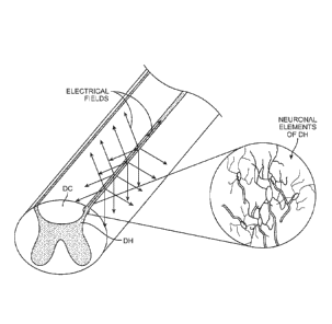
[0013] As illustrated in Fig. 1, the DH can be characterized as central
"butterfly" shaped central area of gray matter (neuronal cell bodies)
substantially surrounded by an ellipse-shaped outer area of white matter
5
81802458
(myelinated axons). The DH is the dorsal portion of the "butterfly" shaped
central area of gray matter, which includes neuronal cell terminals, neuronal
cell bodies, dendrites, and axons.
[0014] Activation of large sensory fibers also typically creates the
paresthesia sensation that often accompanies SCS therapy. Although
alternative or artifactual sensations, such as paresthesia, are usually
tolerated relative to the sensation of pain, patients sometimes report these
sensations to be uncomfortable, and therefore, they can be considered an
adverse side-effect to neuromodulation therapy in some cases.
[0015] It has been shown that the neuronal elements (e.g., neurons,
dendrites, axons, cell bodies, and neuronal cell terminals) in the DH can be
preferentially stimulated over the DC neuronal elements by minimizing the
longitudinal gradient of an electrical field generated by a neurostimulation
lead along the DC, thereby providing therapy in the form of pain relief
without
creating the sensation of paresthesia. Such a technique is described in U.S.
Provisional Patent Application Ser. No. 61/911,728, entitled "Systems and
Methods for Delivering Therapy to the Dorsal Horn of a Patient."
[0016] This technique relies, at least partially on the natural phenomenon
that DH fibers and DC fibers have different responses to electrical
stimulation. The strength of stimulation (i.e., depolarizing or
hyperpolarizing)
of the DC fibers and neurons is described by the so-called "activating
function" 32V/3x2 which is proportional to the second-order spatial derivative
of the voltage along the longitudinal axis of the spine. This is partially
because the large myelinated axons in DC are primarily aligned
longitudinally along the spine. On the other hand, the likelihood of
6
CA 2954855 2018-04-27
81802458
generating action potentials in DH fibers and neurons is described by the
"activating
function" aV/ax (otherwise known as the electric field). The DH "activating
function" is
proportional not to the second-order derivative, but to the first-order
derivative of the
voltage along the fiber axis. Accordingly, distance from the electrical field
locus
affects the DH "activating function" less than it affects the DC "activating
function."
[0017] While fibers in the DC run in an axial direction, the neuronal elements
in the
dorsal horn are oriented in many directions, including perpendicular to the
longitudinal axis of the spinal cord. However, the dorsal horn stimulation
technique
described in U.S. Provisional Patent Application Ser. No. 61/911,728,
generates an
1() electrical field that is uniformly in one direction. There, thus,
remains a need for an
improved technique to stimulate the neuronal elements of the dorsal horn.
SUMMARY OF THE INVENTION
[0018] A system for providing therapy to a patient having a medical condition
(e.g.,
chronic pain) is provided. The system comprises means for delivering
electrical
stimulation energy (e.g., anodic) to the spinal cord of the patient in
accordance with a
stimulation program that preferentially stimulates dorsal horn neuronal
elements over
dorsal column neuronal elements in the spinal cord. The electrical stimulation
energy
is delivered to the spinal cord of the patient without creating the sensation
of
paresthesia in the patient. The delivered electrical stimulation energy
generates a
plurality of electrical fields having different orientations that stimulate
the dorsal horn
neuronal elements. For example, the plurality of electrical fields may be
orientated in
different medio-lateral directions or different rostro-caudal directions.
7
CA 2954855 2019-09-05
CA 02954855 2017-01-10
WO 2016/014624
PCT/US2015/041469
[0019] The electrical stimulation energy may be delivered to the spinal cord
of the patient as a pulsed electrical waveform, in which case, the plurality
of
electrical fields may be respectively generated on a pulse-by-pulse basis.
The plurality of electrical fields may achieve temporal summation of
stimulation in the dorsal horn neuronal elements. The electrical stimulation
energy may be delivered from an electrical stimulation lead implanted along
a longitudinal axis of the spinal cord of the patient. The electrical
stimulation
lead may carry a plurality of electrodes, in which case, all of the electrodes
may be activated to generate each electrical field.
[0020] The system may further comprise means for cycling through the
electrical fields multiple times. The electrical fields may, e.g., be
generated
the same number of times for each electrical field cycle, generated a
different number of times for each electrical field cycle, generated in the
same order during the electrical field cycles, generated in a different order
during the electrical field cycles, or bursted on and off at a burst
frequency.
In the latter case, the burst frequency may match a pathological burst
frequency of medical condition.
[0021]
The electrical stimulation energy may be delivered from a plurality of
electrodes implanted adjacent the spinal cord of the patient. In this case,
the
electrodes may be radially segmented electrodes. This system may further
comprise means fordetermining a stimulation threshold for each of the
electrodes, and generating each of the electrical fields based on the
stimulation thresholds of the electrodes. In this case, determining the
stimulation threshold for each of the electrodes may comprise automatically
delivering electrical energy from each of the electrodes at different
8
81802458
amplitudes, automatically measuring an evoked compound action potential in
response to the deliverance of the electrical energy from each of the
electrodes, and
automatically recording the amplitude at which the evoked compound action
potential
is measured for each of the electrodes. Or, determining the stimulation
threshold for
each of the electrodes may comprise automatically delivering electrical energy
from
each of the electrodes at different amplitudes, acquiring feedback from the
patient in
response to the deliverance of the electrical energy from each of the
electrodes, and
automatically recording the amplitude at which paresthesia is perceived by the
patient for each of the electrodes.
[0021a] According to one aspect of the present invention, there is provided a
system
for providing therapy to a patient having a medical condition, comprising:
means for
preferentially stimulating dorsal horn neuronal elements over dorsal column
neuronal
elements by delivering electrical stimulation energy from an electrode array
implanted
in an epidural space to a spinal cord in accordance with a stimulation
program,
wherein the means for preferentially stimulating dorsal horn elements over
dorsal
column neuronal elements includes means for generating from the electrode
array a
plurality of electrical fields having different orientations that stimulate
the dorsal horn
neuronal elements and means for cycling through the plurality of electrical
fields
having different orientations multiple times to target different orientations
of the dorsal
horn neuronal elements, wherein the electrical fields having different
orientations are
generated during electrical field cycles in a same order or in a different
order.
[0022] Other and further aspects and features of the invention will be evident
from
reading the following detailed description of the preferred embodiments, which
are
intended to illustrate, not limit, the invention.
BRIEF DESCRIPTION OF THE DRAWINGS
[0023] The drawings illustrate the design and utility of preferred embodiments
of
the present invention, in which similar elements are referred to by common
reference numerals. In order to better appreciate how the above-recited and
other
advantages and objects of the present inventions are obtained, a more
particular
9
CA 2954855 2019-02-06
81802458
description of the present inventions briefly described above will be rendered
by
reference to specific embodiments thereof, which are illustrated in the
accompanying drawings. Understanding that these drawings depict only typical
embodiments of the invention and are not therefore to be considered limiting
of its
scope, the invention will be described and explained with additional
specificity and
detail through the use of the accompanying drawings in which:
9a
CA 2954855 2019-02-06
CA 02954855 2017-01-10
WO 2016/014624
PCT/US2015/041469
[0024] Fig. 1 is a perspective view of a spinal cord, wherein the neuronal
elements of the dorsal horn are particularly shown;
[0025] Fig. 2 is plan view of one embodiment of a SCS system arranged in
accordance with the present inventions;
[0026] Fig. 3 is a plan view of the SCS system of Fig. 2 in use to perform
spinal cord stimulation (SCS) on a patient;
[0027] Fig. 3 is a plan view of the SCS system of Fig. 1 in use to perform
deep brain stimulation (DBS) on a patient;
[0028] Fig. 4 is a plan view of an implantable pulse generator (IPG) and two
neurostimulation leads used in the SCS system of Fig. 1;
[0029] Fig. 5 is a cross-sectional view of one of the neurostimulation leads
of Fig. 4, taken along the line 5-5;
[0030] Fig. 6 is a perspective view of the spinal cord of a patient, wherein
the SCS system of Fig. 2 is used to generate multiple electrical fields that
stimulate the neuronal elements of the dorsal horn of the spinal cord;
[0031] Figs. 7a-7c are plan views of one of the neurostimulation leads of
Fig. 4, particularly showing the generation of electrical fields at different
medio-lateral directions;
[0032] Figs. 8a-8c are plan views of one of the neurostimulation leads of
Fig. 4, particularly showing the generation of electrical fields at different
rostro-caudal directions; and
[0033] Fig. 9 is a timing diagram of a pulse pattern having electrical fields
that are generated on a pulse-by-pulse basis using the SCS system of Fig.
2.
10
81802458
DETAILED DESCRIPTION OF THE EMBODIMENTS
[0034] Turning first to Fig. 2, an exemplary SCS system 10 constructed in
accordance with the present inventions will now be described. The SCS
system 10 generally comprises a plurality of neurostimulation leads 12 (in
this case, two percutaneous leads 12a and 12b), an implantable pulse
generator (IPG) 14, an external remote control (RC) 16, a User's
Programmer (CP) 18, an External Trial Stimulator (ETS) 20, and an external
charger 22.
[0035] The IPG 14 is physically connected via two lead extensions 24 to the
neurostimulation leads 12, which carry a plurality of electrodes 26 arranged
in an array. In the illustrated embodiment, the neurostimulation leads 12 are
percutaneous leads, and to this end, the electrodes 26 are arranged in-line
along the neurostimulation leads 12. The number of neurostimulation leads
12 illustrated is two, although any suitable number of neurostimulation leads
12 can be provided, including only one. Alternatively, a surgical paddle lead
can be used in place of one or more of the percutaneous leads. As will also
be described in further detail below, the IPG 14 includes pulse generation
circuitry that delivers electrical stimulation energy in the form of a pulsed
electrical waveform (i.e., a temporal series of electrical pulses) to the
electrode array 26 in accordance with a set of stimulation parameters. The
IPG 14 and neurostimulation leads 12 can be provided as an implantable
neurostimulation kit, along with, e.g., a hollow needle, a stylet, a tunneling
tool, and a tunneling straw. Further details discussing implantable kits are
disclosed in U.S. Application Ser. No. 61/030,506, entitled "Temporary
Neurostimulation Lead Identification Device."
11
CA 2954855 2018-04-27
CA 02954855 2017-01-10
WO 2016/014624
PCT/US2015/041469
[0036] The ETS 20 may also be physically connected via percutaneous lead
extensions 28 or external cable 30 to the neurostimulation lead 12. The ETS
20, which has similar pulse generation circuitry as the IPG 14, also delivers
electrical stimulation energy in the form of a pulsed electrical waveform to
the electrode array 26 in accordance with a set of stimulation parameters.
The major difference between the ETS 20 and the IPG 14 is that the ETS 20
is a non-implantable device that is used on a trial basis after the
neurostimulation lead 12 has been implanted and prior to implantation of the
IPG 14, to test the responsiveness of the stimulation that is to be provided.
Thus, any functions described herein with respect to the IPG 14 can likewise
be performed with respect to the ETS 20.
[0037] The RC 16 may be used to telemetrically control the ETS 20 via a bi-
directional RF communications link 32. Once the IPG 14 and stimulation
leads 12 are implanted, the RC 16 may be used to telemetrically control the
IPG 14 via a bi-directional RF communications link 34. Such control allows
the IPG 14 to be turned on or off and to be programmed with different
stimulation programs after implantation. Once the IPG 14 has been
programmed, and its power source has been charged or otherwise
replenished, the IPG 14 may function as programmed without the RC 16
being present.
[0038] The CP 18 provides user detailed stimulation parameters for
programming the IPG 14 and ETS 20 in the operating room and in follow-up
sessions. The CP 18 may perform this function by indirectly communicating
with the IPG 14 or ETS 20, through the RC 16, via an IR communications
link 36. Alternatively, the CP 18 may directly communicate with the IPG 14
or ETS 20 via an RF communications link (not shown).
12
81802458
[0039] The external charger 22 is a portable device used to
transcutaneously charge the IPG 14 via an inductive link 38. Once the IPG
14 has been programmed, and its power source has been charged by the
external charger 22 or otherwise replenished, the IPG 14 may function as
programmed without the RC 16 or CP 18 being present.
[0040] For the purposes of this specification, the terms "neurostimulator,"
"stimulator," "neurostimulation," and "stimulation" generally refer to the
delivery of electrical energy that affects the neuronal activity of neural
tissue,
which may be excitatory or inhibitory; for example by initiating an action
potential, inhibiting or blocking the propagation of action potentials,
affecting
changes in neurotransmitter/neuromodulator release or uptake, and inducing
changes in neuro-plasticity or neurogenesis of tissue. For purposes of
brevity, the details of the RC 16, ETS 20, and external charger 22 will not be
described herein. Details of exemplary embodiments of these components
are disclosed in U.S. Patent No. 6,895,280.
[0041] Referring to Fig. 3, the neurostimulation leads 12 are implanted at an
initial position within the spinal column 42 of a patient 40. The preferred
placement of the neurostimulation leads 12 is adjacent, i.e., resting near, or
upon the dura, adjacent to the spinal cord area to be stimulated. In the
illustrated embodiment, the neurostimulation leads 12 are implanted along a
longitudinal axis of the spinal cord of the patient 40. Due to the lack of
space
near the location where the neurostimulation leads 12 exit the spinal column
42, the IPG 14 is generally implanted in a surgically-made pocket either in
the abdomen or above the buttocks. The IPG 14 may, of course, also be
implanted in other locations of the patient's body. The lead extensions 24
13
CA 2954855 2018-04-27
81802458
facilitate locating the IPG 14 away from the exit point of the
neurostimulation
leads 12. As there shown, the CP 18 communicates with the IPG 14 via the
RC 16. After implantation, the IPG 14 can be operated to generate a volume
of activation relative to the target tissue to be treated, thereby providing
the
therapeutic stimulation under control of the patient.
[0042] Referring now to Fig. 4, the external features of the neurostimulation
leads 12a, 12b and the IPG 14 will be briefly described. The electrodes 26
take the form of segmented electrodes that are circumferentially and axially
disposed about each of the respective neurostimulation leads 12a, 12b. By
way of non-limiting example, and with further reference to Fig. 5, each
neurostimulation lead 12 may carry sixteen electrodes, arranged as four
rings of electrodes (the first ring consisting of electrodes E1-E4; the second
ring consisting of electrodes E5-E8; the third ring consisting of electrodes
E9-E12; and the fourth ring consisting of electrodes El 3-E16) or four axial
columns of electrodes (the first column consisting of electrodes El, E5, E9,
and E13; the second column consisting of electrodes E2, E6, El 0, and E14;
the third column consisting of electrodes E3, E7, Ell, and El 5; and the
fourth column consisting of electrodes E4, E8, E12, and E16). The actual
number and shape of leads and electrodes will, of course, vary according to
the intended application. Further details describing the construction and
method of manufacturing percutaneous stimulation leads are disclosed in
U.S. Patent Application Ser. No. 11/689,918, entitled "Lead Assembly and
Method of Making Same," and U.S. Patent Application Ser. No. 11/565,547,
entitled "Cylindrical Multi-Contact Electrode Lead for Neural Stimulation and
Method of Making Same."
14
CA 2954855 2018-04-27
CA 02954855 2017-01-10
WO 2016/014624
PCT/US2015/041469
[0043] The IPG 14 comprises an outer case 50 for housing the electronic
and other components (described in further detail below). The outer case 50
is composed of an electrically conductive, biocompatible material, such as
titanium, and forms a hermetically sealed compartment wherein the internal
electronics are protected from the body tissue and fluids. In some cases,
the outer case 50 may serve as an electrode. The IPG 14 further comprises
a connector 52 to which the proximal ends of the neurostimulation leads 12
mate in a manner that electrically couples the electrodes 26 to the internal
electronics (described in further detail below) within the outer case 50. To
this end, the connector 52 includes two ports (not shown) for receiving the
proximal ends of the leads 12. In the case where the lead extensions 24 are
used, the ports may instead receive the proximal ends of such lead
extensions 24.
[0044] As briefly discussed above, the IPG 14 includes circuitry that provides
electrical stimulation energy to the electrodes 26 in accordance with a set of
parameters. Such stimulation parameters may comprise electrode
combinations, which define the electrodes that are activated as anodes
(positive), cathodes (negative), and turned off (zero), percentage of
stimulation energy assigned to each electrode (fractionalized electrode
configurations), and electrical pulse parameters, which define the pulse
amplitude (measured in milliamps or volts depending on whether the IPG 14
supplies constant current or constant voltage to the electrode array 26),
pulse width (measured in microseconds), pulse rate (measured in pulses per
second), and burst rate (measured as the stimulation on duration X and
stimulation off duration Y). As will be described in further detail below, the
CA 02954855 2017-01-10
WO 2016/014624
PCT/US2015/041469
IPG 14 also includes circuitry that provides electrical signals, and measured
electrical impedance in response to the electrical signals.
[0045] With respect to the pulsed electrical waveform provided during
operation of the SCS system 10, electrodes that are selected to transmit or
receive electrical energy are referred to herein as "activated," while
electrodes that are not selected to transmit or receive electrical energy are
referred to herein as "non-activated." Electrical energy delivery will occur
between two (or more) electrodes, one of which may be the IPG case 50, so
that the electrical current has a path from the energy source contained within
the IPG case 50 to the tissue and a sink path from the tissue to the energy
source contained within the case. Electrical energy may be transmitted to
the tissue in a monopolar or multipolar (e.g., bipolar, tripolar, etc.)
fashion.
[0046] Monopolar delivery occurs when a selected one or more of the lead
electrodes 26 is activated along with the case 50 of the IPG 14, so that
electrical energy is transmitted between the selected electrode 26 and case
50. Monopolar delivery may also occur when one or more of the lead
electrodes 26 are activated along with a large group of lead electrodes
located remotely from the one or more lead electrodes 26 so as to create a
monopolar effect; that is, electrical energy is delivered from the one or more
lead electrodes 26 in a relatively isotropic manner. Bipolar delivery occurs
when two of the lead electrodes 26 are activated as anode and cathode, so
that electrical energy is transmitted between the selected electrodes 26.
Tripolar delivery occurs when three of the lead electrodes 26 are activated,
two as anodes and the remaining one as a cathode, or two as cathodes and
the remaining one as an anode.
16
CA 02954855 2017-01-10
WO 2016/014624
PCT/US2015/041469
[0047] The IPG 14 comprises electronic components, such as a memory 54,
controller/processor (e.g., a microcontroller) 56, monitoring circuitry 58,
telemetry circuitry 60, a battery 62, stimulation output circuitry 64, and
other
suitable components known to those skilled in the art.
[0048] The memory 54 is configured for storing programming packages,
stimulation parameters, measured physiological information, and other
important information necessary for proper functioning of the IPG 14. The
microcontroller 56 executes a suitable program stored in memory 54 for
directing and controlling the neurostimulation performed by IPG 14. The
monitoring circuitry 58 is configured for monitoring the status of various
nodes or other points throughout the IPG 14, e.g., power supply voltages,
temperature, battery voltage, and the like. Notably, the electrodes 26 fit
snugly within the patient, and because the tissue is conductive, electrical
measurements can be taken between the electrodes 26. Thus, the
monitoring circuitry 58 is configured for taking such electrical measurements
(e.g., electrode impedance, field potential, evoked action potentials, etc.)
for
performing such functions as detecting fault conditions between the
electrodes 26 and the stimulation output circuitry 64, determining the
coupling efficiency between the electrodes 26 and the tissue, determining
the posture/patient activity of the patient, facilitating lead migration
detection.
[0049] More significant to the present inventions, an evoked potential
measurement technique can be used to calibrate the stimulation energy
delivered to the spinal cord. The evoked potential measurement technique
may be performed by generating an electrical field at one of the electrodes
26, which is strong enough to depolarize the neurons adjacent the
stimulating electrode beyond a threshold level, thereby inducing the firing of
17
CA 02954855 2017-01-10
WO 2016/014624
PCT/US2015/041469
action potentials (APs) that propagate along the neural fibers. Such
stimulation is preferably supra-threshold, but not uncomfortable. A suitable
stimulation pulse for this purpose is, for example, 4 mA for 200 ps. While a
selected one of the electrodes 26 is activated to generate the electrical
field,
a selected one or ones of the electrodes 26 (different from the activated
electrode) is operated to record a measurable deviation in the voltage
caused by the evoked potential due to the stimulation pulse at the
stimulating electrode.
[0050] The telemetry circuitry 60, including an antenna (not shown), is
configured for receiving programming data (e.g., the operating program
and/or stimulation parameters, including pulse patterns) from the RC 16
and/or CP 18 in an appropriate modulated carrier signal, which the
programming data is then stored in the memory 54. The telemetry circuitry
60 is also configured for transmitting status data to the RC 16 and/or CF 18
in an appropriate modulated carrier signal. The battery 62, which may be a
rechargeable lithium-ion or lithium-ion polymer battery, provides operating
power to IPG 14. The stimulation output circuitry 64 is configured for, under
control of the microcontroller 56, generating and delivering electrical
energy,
in the form of electrical pulse trains, to each of the electrodes 26, as well
as
any electrical signals needed for acquiring electrical measurements.
[0051] Notably, while the microcontroller 56 is shown in Fig. 4 as a single
device, the processing functions and controlling functions can be performed
by a separate controller and processor. Thus, it can be appreciated that the
controlling functions performed by the IPG 14 can be performed by a
controller, and the processing functions performed by the IPG 14 can be
performed by a processor. Additional details concerning the above-
18
81802458
described and other IPGs may be found in U.S. Patent No. 6,516,227, U.S.
Patent Publication No. 2003/0139781, and U.S. Patent Application Ser. No.
11/138,632, entitled "Low Power Loss Current Digital-to-Analog Converter
Used in an Implantable Pulse Generator." It should be noted that rather
than an IPG, the SCS system 10 may alternatively utilize an implantable
receiver-modulator (not shown) connected to the leads 12. In this case,
the power source, e.g., a battery, for powering the implanted receiver,
as well as control circuitry to command the receiver-modulator, will be
contained in an external controller inductively coupled to the receiver-
modulator
via an electromagnetic link. Data/power signals are transcutaneously
coupled from a cable-connected transmission coil placed over the
implanted receiver-modulator. The implanted receiver-modulator receives
the signal and generates the stimulation in accordance with the
control signals.
[0052] More significant to the present inventions, the SCS system 10
delivers electrical stimulation energy to the spinal cord of the patient in
accordance with a stimulation program that preferentially stimulates dorsal
horn neuronal elements over dorsal column neuronal elements in the spinal
cord.
[0053] To this end, the current delivered from the electrodes 26 is
fractionalized, such that the electrical field generated by the
neurostimulation
lead(s) 12 has an electrical field strength in the longitudinal direction that
is
approximately equal, resulting in a voltage gradient of approximately zero
along the dorsal column. This substantially constant electrical field forms a
small longitudinal gradient, which minimizes activation of the large
myelinated axons in the dorsal column. In contrast, the electrical field
19
CA 2954855 2018-04-27
CA 02954855 2017-01-10
WO 2016/014624
PCT/US2015/041469
generated by the neurostimulation lead(s) 12 has an electrical field strength
in the transverse direction that substantially differs, resulting a strong
voltage
gradient in the dorsal horn. In particular, the transverse electrical field
strength is greatest adjacent the neurostimulation lead(s) 12 and falls off
laterally, resulting in a sizable gradient in the transverse direction, which
activates the neural cell terminals in the dorsal horn. Thus, the
substantially
constant longitudinal electrical field and the large gradient in the
transverse
electrical field favor stimulation of dorsal horn neuronal elements over
dorsal
column neuronal elements. This electrical field makes the dorsal column
neuronal elements even less excitable relative to the dorsal horn neuronal
elements. In this manner, the perception of paresthesia is eliminated or at
least minimized. In the illustrated embodiment, the all of the electrodes 26
on the neurostimulation leads 12 are preferably activated to maximize the
stimulation of the dorsal horn neuronal elements along the leads 12.
[0054] Calibration techniques (described below) may be used to determine
the proper current fractionalization for the electrodes 26. With the current
fractionalized to a plurality of electrodes 26 on the neurostimulation lead
12,
the resulting field can be calculated by superimposing the fields generated
by the current delivered to each electrode 26. In the illustrated embodiment,
the electrodes 26 on the neurostimulation lead 12(s) are anodic, while the
outer case 44 of the IPG 14 is cathodic. In this manner, a monopolar anodic
electrical field is generated by the SCS system 10. Further details
discussing techniques for preferentially stimulating dorsal horn neuronal
elements over dorsal column neuronal elements are described in U.S.
Provisional Patent Application Ser. No. 61/911,728, entitled "Systems and
81802458
Methods for Delivering Therapy to the Dorsal Horn of a Patient:
[0055] Significantly, the SCS system 10 delivers the electrical energy to the
spinal cord of the patient by generating a plurality of electrical fields
having
different orientations that target the different directions/orientations of
the
dorsal horn neuronal elements, as illustrated in Fig. 6. In this manner, all,
or
at least a significant amount of, the dorsal horn neuronal elements will be
stimulated by at least one of the electrical fields.
[0056] In the illustrated embodiment, the electrical fields are oriented in
different medio-lateral directions (i.e., the direction of the electrical
fields as
projected on a transverse plane through the spinal cord). To generate
electrical fields in different medio-lateral directions, the electrodes 26 may
have different current fractionalizations in the radial direction. For
example,
referring back to Fig. 5, the first column of electrodes El, E5, E9, and El 3
may deliver 50% of the anodic current, and the second column of electrodes
E2, E6, El 0, and E14 may deliver the remaining 50% of the anodic current
to orient the electrical field in one medio-lateral direction, as illustrated
in Fig.
7a. The first column of electrodes El, E5, E9, and El 3 may deliver 75% of
the anodic current, and the second column of electrodes E2, E6, E10, and
E14 may deliver the remaining 25% of the anodic current to orient the
electrical field in one medio-lateral direction to orient the electrical field
in
another medio-lateral direction, as illustrated in Fig. 7b. The first column
of
electrodes El, E5, E9, and E13 may deliver 100% of the anodic current to
orient the electrical field in one medio-lateral direction to orient the
electrical
field in another medio-lateral direction, as illustrated in Fig. 7c.
21
CA 2954855 2018-04-27
CA 02954855 2017-01-10
WO 2016/014624
PCT/US2015/041469
[0057] Although it is desirable that the electrical fields preferentially
stimulate
dorsal horn neuronal elements over the dorsal column neuronal elements, as
discussed above, the electrical fields may still be oriented in different
rostro-
caudal directions (i.e., the direction of the electrical fields as projected
on a
longitudinal plane through the spinal cord), although preferably not in an
orientation that will result in the perception of paresthesia. To generate
electrical fields in different rostro-caudal directions, the electrodes 26 may
have different current fractionalizations in the longitudinal direction. For
example, referring back to Fig. 5, each of the first ring of electrodes El-E4,
the second ring of electrodes E5-E8; the third ring of electrodes E9-E12, and
the fourth ring of electrodes E13-E16 may deliver 25% of the anodic current
to orient the electrical field in one rostro-caudal direction, as illustrated
in
Fig. 8a. The first ring of electrodes E1-E4, may deliver 10% of the anodic
current, the second ring of electrodes E5-E8 may deliver 25% of the anodic
current, the third ring of electrodes E9-E12 may deliver 30% of the anodic
current, and the fourth ring of electrodes E13-E16 may deliver 35% of the
anodic current to orient the electrical field in one rostro-caudal direction,
as
illustrated in Fig. 8b. The first ring of electrodes El-E4, may deliver 5% of
the anodic current, the second ring of electrodes E5-E8 may deliver 20% of
the anodic current, the third ring of electrodes E9-E12 may deliver 35% of
the anodic current, and the fourth ring of electrodes E13-E16 may deliver
40% of the anodic current to orient the electrical field in one rostro-caudal
direction, as illustrated in Fig. 8c.
[0058] The different electrical fields generated by the SCS system 10
preferably achieve a temporal summation of stimulation in the dorsal horn
neuronal elements. To ensure this temporal summation of stimulation, the
22
81802458
electrical fields can be generated respectively on a pulse-by-pulse basis.
For example, as illustrated in Fig. 9, a first electrical field can be
generated
by the electrodes 26 (using a first current fractionalization) during a first
electrical pulse of the pulsed waveform, a second different electrical field
can
be generated by the electrodes 26 (using a second different current
fractionalization) during a second electrical pulse of the pulsed waveform, a
third different electrical field can be generated by the electrodes 26 (using
a
third different current fractionalization) during a third electrical pulse of
the
pulsed waveform, a fourth different electrical field can be generated by the
electrodes 26 (using a fourth different current fractionalized) during a
fourth
electrical pulse of the pulsed waveform, and so forth. Further details on the
delivery of different electrical fields on a pulse-by-pulse basis are set
forth in
U.S. Provisional Patent Application Ser. No. 62/020,836.
[0059] The electrical fields generated by the SCS system 10 may be rotated
or cycled through multiple times under a timing scheme. The electrical field
cycling can be accomplished in any one of a variety of manners. In one
embodiment, the different electrical fields are generated in the same (or
regular) order during the electrical field cycles. For example, if four
electrical
fields labeled 1-4 are generated, the order in which these electrical fields
are
generated may be {2, 3, 1, 4}, {2, 3, 1, 4}, {2, 3, 1, 4}, etc. The different
electrical field may alternatively be generated in a different order (or
irregular) during the electrical field cycles. For example, the order in which
electrical fields 1-4 are generated may be {1, 2, 3, 4}, {3, 1, 2, 4}, {4, 1,
3, 2},
{1,2, 3, 4}, etc.
23
CA 2954855 2018-04-27
81802458
[0060] Although electrical fields 1-4 have been described as being
generated the same number of times for each electrical field cycle (in the
cases above, one time per each cycle), the electrical fields 1-4 may be
generated a different number of times for each electrical field cycle. That
is,
the cycling can be biased towards one electrical field relative to another
electrical field. For example, electrical fields 1-4 may be generated during
the electrical field cycles as follows: {1, 2, 2, 2, 3, 3, 4), {1, 2, 2, 2, 3,
3, 4],
{1, 2, 2, 2, 3, 3, 4}, etc. Thus, in this case, electrical field 1 is
generated
once, electrical field 2 is generated thrice, electrical field 3 is generated
twice, and electrical field 4 is generated once per electrical field cycle.
[0061] In the above exemplary cases, the electrical fields 1-4 can be
generated at a continuous pulse rate. However, in an optional embodiment,
the electrical field cycles can be bursted on and off. For example, an
electrical field cycle {2, 3, 1, 4] can be repeatedly bursted at a defined
frequency (e.g., a cycle burst every 100ms). In one particularly useful
embodiment, the burst frequency matches the pathological burst frequency
of the neurological signals that cause the chronic pain.
[0062] Although the interpulse interval (i.e., the time between adjacent
pulses), pulse amplitude, and pulse duration during the electrical field
cycles
has been described as being uniform, the interpulse interval, pulse
amplitude, and/or pulse duration may vary within the electrical field cycle,
as
described in U.S. Provisional Patent Application Ser. No. 62/020,836.
[0063] Because the stimulation threshold (i.e., the electrical current needed
on an activated electrode to stimulate adjacent tissue) varies from patient to
24
CA 2954855 2018-04-27
CA 02954855 2017-01-10
WO 2016/014624
PCT/US2015/041469
patient and from electrode 26 to electrode 26 within a patient, a more
accurate fractionalization of the current between electrodes 26 to generate
the various electrical fields requires modification of the fractionalization
based on the stimulation threshold at each electrode. To this end, the
electrodes may be calibrated by determining the stimulation threshold level
(i.e., the electrical current needed on an activated electrode to stimulate
adjacent tissue) for each of the electrodes and using the stimulation
threshold levels to determine the fractionalized electrical current values for
generating the electrical fields. This calibration technique may involve
calculating a driving force directed to each electrode.
[0064] Preferably, the stimulation threshold for each of the electrodes 26 is
determined by automatically delivering electrical energy from each of the
electrodes 26 at different amplitudes, automatically measuring an evoked
compound action potential in response to the deliverance of the electrical
energy from each of the electrodes 26, and automatically recording the
amplitude at which the evoked compound action potential is measured for
each of the electrodes 26. The electrical energy may be delivered to each
electrode in a monopolar mode as either anodic or cathodic electrical
energy. This automated electrode calibration technique can be updated
periodically or in response to a particular event, such as a posture change of
the patient.
[0065] Determination of the stimulation thresholds may be binary in nature,
meaning that the presence or absence of a measured evoked compound
action potential either indicates that a stimulation threshold has been
reached or not reached for a particular electrode, or the determination of the
stimulation thresholds may be more sophisticated in nature. The maximum
CA 02954855 2017-01-10
WO 2016/014624
PCT/US2015/041469
amplitude of the electrical energy delivered from each electrode should be
managed so that the patient does not perceive the electrical stimulation too
much, although since single electrical pulses can be used, the patient may
not perceive much even at amplitudes that would be strong enough to cause
continuous stimulation.
[0066] Optionally, the stimulation threshold determined previous electrodes,
including the first calibrated electrode, may be used as a starting point for
the stimulation threshold determination for subsequent electrodes, so that
the amplitude need not be initially set to zero for each subsequently
electrode in order to speed up the calibration process. For example, the
electrical energy may be transitioned between electrodes at an amplitude
where the patient barely perceives stimulation, a comfortable level, or some
other constant level.
[0067] Alternatively, the stimulation threshold for each of the electrodes 26
may be determined by automatically delivering electrical energy from each of
the electrodes 26 at different amplitudes, acquiring feedback from the
patient, and in particular communicating when the patient perceives
paresthesia, in response to the deliverance of the electrical energy from
each of the electrodes 26, and automatically recording the amplitude at
which paresthesia is perceived by the patient for each of the electrodes 26.
However, it should be appreciated that measuring evoked compound action
potentials, as opposed to relying on subjective patient feedback, is objective
in nature, can be performed quickly, and can be determined using a
relatively small number of electrical pulses as opposed perceiving
paresthesia, which requires a relatively large number of electrical pulses.
26
CA 02954855 2017-01-10
WO 2016/014624
PCT/US2015/041469
[0068] Although particular embodiments of the present inventions have been
shown and described, it will be understood that it is not intended to limit
the
present inventions to the preferred embodiments, and it will be obvious to
those skilled in the art that various changes and modifications may be made
without departing from the spirit and scope of the present inventions. Thus,
the present inventions are intended to cover alternatives, modifications, and
equivalents, which may be included within the spirit and scope of the present
inventions as defined by the claims.
27