Note: Descriptions are shown in the official language in which they were submitted.
LAUNDRY WASHING METHOD
[TECHNICAL FIELD]
[0001] The present invention relates to a washing method for washing laundry,
and more
particularly relates to a washing device with which laundry is washed in a
laundry tub that is
filled with a washing liquid including water, a petroleum-based solvent or an
organic solvent,
and the like.
[BACKGROUND ART]
[0002] With a conventional washing device, it is very common for it to be
equipped with a
laundry tub whose rotational axis is in the horizontal direction or is
inclined from the horizontal
direction (hereinafter referred to simply as the "horizontal inclined
direction"). With a washing
device comprising a laundry tub (drum) whose rotational axis is in the
horizontal direction or the
horizontal inclined direction, the laundry tub is spun so that the laundry is
moved to the upper
side of the laundry tub by a baffle (vane) that protrudes from the inner wall
surface of the
laundry tub, after which the laundry is allowed to fall under its own weight.
The laundry is
washed by the impact caused by the collision with the inner wall surface of
the laundry tub when
the laundry falls (impact washing mode).
[0003] Meanwhile, the applicant has proposed a washing method (see Patent
Literature 1) and
washing devices (see Patent Literature 2 and 3) in which a laundry tub whose
center axis is in the
horizontal direction is installed in the interior of a casing (water tank),
this casing is filled with a
washing liquid, and the laundry tub (drum) is spun, which washes the laundry
held in the laundry
tub by suspending it in the washing liquid. With the washing devices in the
above-mentioned
Patent Literature, bumps that are continuous in the peripheral direction are
provided on the inner
wall surface of the laundry tub, and this tub is spun to generate eddy
currents at the bumps on the
inner wall surface of the laundry tub, in the washing liquid on the inner wall
surface side of the
laundry tub. These eddy currents are formed continuously along the inner wall
surface of the
laundry tub, which generates a large flow along the rotation of the laundry
tub in the washing
liquid inside the laundry tub. Since the large flow and the eddy currents thus
generated affect the
laundry, the laundry is suspended and spreads out as if drifting within the
laundry tub.
Accordingly, not only is there a larger contact surface between the washing
liquid and the
1.
CA 2954860 2018-06-21
CA 02954860 2017-01-11
laundry, but the washing liquid penetrates the laundry with higher force, and
as a result the
washing effect of the washing liquid is improved against soil on the laundry.
[0004] This vortex-like rotational flow is formed in the various recesses, so
the washing liquid
that fills the casing flows at different speeds in a substantially concentric
circular shape in the
radial direction of the laundry tub, forming a pressure distribution in the
radial direction of the
laundry tub. The pressure distribution formed in the radial direction of the
laundry tub suspends
the laundry within the laundry tub, so the result is that the laundry that is
drifting suspended in
the washing liquid spreads out, which promotes the washing effect and also
prevents damage to
the laundry. The washing mode in the washing devices in the Patent Literature
give above shall
be termed "simulated zero-gravity washing mode."
[0005] In Patent Literature 4, it is proposed that even laundry with a low
specific gravity, etc.,
can be properly washed by changing the liquid level of the washing liquid
supplied into the
laundry tub according to the type of laundry. In Patent Literature 5, it is
proposed that the liquid
level of the washing liquid supplied into the laundry tub is determined, and
the system switches
between an impact washing mode and a simulated zero-gravity washing mode
according to the
liquid level of the washing liquid.
[PRIOR ART DOCUMENT]
[PATENT LITERATURE]
[0006] Patent Literature 1: Japanese Laid-Open Patent Application Publication
No. 2008-5853
Patent Literature 2: Japanese Laid-Open Patent Application Publication No.
2008-12274
Patent Literature 3: Japanese Laid-Open Patent Application Publication No.
2010-22645
Patent Literature 4: Japanese Laid-Open Patent Application Publication No.
2011-
115249
Patent Literature 5: Japanese Laid-Open Patent Application Publication No.
2012-24465
[SUMMARY OF THE INVENTION]
[PROBLEMS TO BE SOLVED BY THE INVENTION]
[0007] The washing liquids utilized in washing with a washing device such as
this are
classified into water-based washing liquids such as water or a solvent in
which a surfactant is
admixed in water, and nonaqueous washing liquids such as petroleum-based
solvents and
organic solvents. When a water-based washing liquid is used, water-soluble
stains on the
laundry come out, but some laundry fabrics or fibers may be damaged, shrink,
or harden, so the
2
CA 02954860 2017-01-11
laundry may end up being in a bad state after washing. On the other hand, when
a nonaqueous
washing liquid is used, the risk of damage to the laundry that is encountered
with water-based
washing liquids can be avoided, but water-soluble stains cannot be reliably
removed.
[0008] However, with the simulated zero-gravity washing modes proposed by the
applicant in
Patent Literature 1 to 5, shrinkage and hardening of fabrics and fibers of the
laundry are less
likely to be caused by a water-based washing liquid, and damage can be further
prevented. Also,
stains can be removed even without using an organic solvent or a petroleum-
based solvent as the
washing liquid, so this washing method is extremely environmentally friendly.
[0009] With the washing device in Patent Literature 5, whether to use an
impact washing mode
or a simulated zero-gravity washing mode is determined by the type of laundry,
and the liquid
level of the washing liquid is determined to match. However, even better stain
removal can be
anticipated if the same load of laundry is subjected to both impact washing
mode and simulated
zero-gravity washing mode.
[0010] The present invention was conceived in an effort to solve the above
problem, and
provides a washing method with which the stain removal effect from a washing
operation lasting
a relatively short time can be improved by combining an impact washing mode
and a simulated
zero-gravity washing mode for the same load of laundry.
[MEANS TO SOLVE THE PROBLEMS]
[0011] To achieve the stated object, the primary feature is a washing method
used in a washing
device comprising a laundry tub that is spun by a rotary shaft that is
horizontal or is inclined
towards the horizontal direction from the vertical direction and in the
interior of which laundry is
held, a casing that covers the laundry tub and into which a washing liquid is
supplied, a bumpy
curved surface that is provided on the inner wall surface of the laundry tub
and that is bumpy in
the radial direction of the laundry tub, and at least one baffle that
protrudes from the inner wall
surface of the laundry tub in the radial direction of the laundry tub and
whose height in the radial
direction of the laundry tub is greater than the height of the convex parts of
the bumpy curved
surface, the method comprising as steps for washing laundry a first washing
step of suspending
and washing the laundry in a washing liquid that is supplied to the laundry
tub, and a second
washing step of agitating the laundry with the baffle and washing it in the
washing liquid at a
lower liquid level than the liquid level of the washing liquid supplied to the
laundry tub in the
first washing step, wherein the liquid level of the washing liquid is
continuously or intermittently
3
CA 02954860 2017-01-11
increased or decreased between the first washing step and the second washing
step while the
laundry tub is spun.
[EFFECTS OF THE INVENTION]
[0012] With the present invention, the laundry stain removal effect can be
improved by
combining an impact washing mode and a simulated zero-gravity washing mode on
the same
load of laundry.
[BRIEF DESCRIPTION OF THE DRAWINGS]
[0013] FIG. 1 is a simplified oblique view of the configuration of the washing
device used in
the washing method of the present invention;
FIG. 2 is a simplified oblique view of the configuration of the laundry tub
provided inside
the casing of the washing device in FIG. 1;
FIG. 3 is a simplified cross section of the laundry tub in a direction
perpendicular to the
rotational axis of the washing device shown in FIG. 2;
FIG. 4 is a block diagram of the simplified configuration of the control
system and the
piping system in the washing device;
FIG. 5 is a graph of an example of the change in the liquid level in the
laundry tub with
the washing method of the present invention;
FIG. 6 is a graph of an example of the change in the liquid level in the
laundry tub with
the washing method of the present invention; and
FIG. 7 is a graph of an example of the change in the liquid level in the
laundry tub with
the washing method of the present invention.
[EMBODIMENTS TO CARRY OUT THE INVENTION]
[0014] An embodiment of the present invention will now be described through
reference to the
drawings. FIG. I is a simplified oblique view of the configuration of the
washing device used in
the washing method of the present invention. FIG. 2 is a simplified oblique
view of the
configuration of the laundry tub provided inside the casing of the washing
device in FIG. I. FIG.
3 is a simplified cross section of the laundry tub in a direction
perpendicular to the rotational axis
of the washing device shown in FIG. 2. FIG. 4 is a simplified block diagram of
the control
system and the piping system in the washing device.
[0015] (1) Configuration of Washing device
4
CA 02954860 2017-01-11
The washing device shown in FIG. 1 comprises a casing 1 into the interior of
which is
supplied a washing liquid, a cylindrical laundry tub 2 provided in the
interior of this casing 1, a
door 3 that is provided to open up the front side of the casing 1 and that
covers a laundry loading
opening 11, a rotary shaft 4 that passes through the casing 1 and is connected
to the laundry tub 2,
and a drive mechanism 5 that transmits rotary force through the rotary shaft 4
and rotates the
laundry tub 2. The casing 1 and the laundry tub 2 shown in FIG. 1 are each
configured in a
cylindrical shape whose center axis is inclined towards the horizontal
direction from the vertical
direction. Specifically, the laundry tub 2 spins inside the casing 1, with its
rotational axis being
the center axis, which is either horizontal or a horizontal inclined
direction. The casing 1 is not
limited to having a cylindrical shape with a cross section that is concentric
with the laundry tub 2,
and may have any shape that allows the laundry tub 2 to spin freely in its
interior.
[0016] As shown in FIG. 1, the door 3 has a protruding part that partially
sticks into the casing
1 from the loading opening 11, and when the loading opening 11 is closed off
by the door 3, the
protruding part of the door 3 mates with the loading opening 11, the casing I
thereby being
sealed by the door 3 so that the washing liquid will not leak out. Also, the
door 3 may comprise
a window that is made of a transparent material such as glass or acrylic, so
that the user can see
the inside of the casing 1 when the casing 1 has been closed off. 'this allows
the user to visually
check the amount of washing liquid supplied into the casing 1, the state of
the laundry during
washing, and so forth. The drive mechanism 5 may be constituted by an electric
motor equipped
with the rotary shaft 4, or may be constituted by an electric motor that
intermittently rotates the
rotary shaft 4 and by a pulley and belt that transmit the rotation of the
electric motor to the rotary
shaft 4. Also, since this drive mechanism 5 is provided on the outside of the
casing I, the rotary
shaft 4 is inserted into the casing 1 and connected to the laundry tub 2.
Consequently, the casing
1 is provided with a bearing into which the rotary shaft 4 is inserted. This
bearing has a sealed
structured so that the washing liquid inside the casing 1 will not leak out.
[0017] The configuration of the laundry tub 2 in the washing device thus
configured will now
be described through reference to FIGS. 2 to 4. As shown in FIG. 2, the
laundry tub 2, whose
rotational axis is horizontal or in the horizontal inclined direction, has a
basket shape that has an
opening 21 on one bottom face. The inner wall surface of the laundry tub 2
comprises bumpy
curved surfaces 22 having a bumpy shape that is continuous in the peripheral
direction in a cross
section perpendicular to the rotational axis of the laundry tub 2, slits 23
made so that their
CA 02954860 2017-01-11
lengthwise direction is the direction of the rotational axis of the laundry
tub 2, and baffles 25
provided on parts of the bumpy curved surfaces 22. As shown in FIG. 3, the
bumpy curved
surfaces 22 and the slits 23 are formed alternately along the peripheral
direction in a cross
section of the inner wall surface of the laundry tub 2 that is perpendicular
to the rotational axis of
the laundry tub 2. In FIG. 2, the slits 23 are spaced evenly, and the bumpy
curved surfaces 22
are formed in between the slits 23, but the slits 23 may instead be provided
at different spacings,
and the bumpy curved surfaces 22 formed in between the various slits 23.
[0018] As shown in FIGS. 2 and 3, the bumpy curved surfaces 22 formed on the
inner wall
surface of the laundry tub 2 are formed by a curved surface that is continuous
in the rotational
axis direction of the laundry tub 2 in a cross section of a bumpy shape that
is perpendicular to the
rotational axis of the laundry tub 2. Specifically, concave parts 22a and
convex parts 22b, whose
lengthwise direction is the rotational axis direction of the laundry tub 2,
are formed alternately
and continuously along the peripheral direction perpendicular to the
rotational axis of the laundry
tub 2, thus constituting the bumpy curved surfaces 22 on the inner wall
surface of the laundry tub
2. Also, since the slits 23 go through from the inner wall of the laundry tub
2 to the outer wall,
these slits 23 allow the washing liquid inside the laundry tub 2 to be
discharged into the region
between the casing 1 and the laundry tub 2, and allow the washing liquid
inside the region
between the casing 1 and the laundry tub 2 to flow into the laundry tub 2.
[0019] With the configuration in FIG. 2, the slits 23 are formed such that
their lengthwise
direction is the rotational axis direction of the laundry tub 2, but may
instead by formed by a
plurality of holes arranged in the rotational axis direction of the laundry
tub 2. Also, these slits
23 need not be provided on just the inner wall surface that serves as the
peripheral surface of the
laundry tub 2, and may also be provided on the bottom face opposite the
opening 21.
Alternatively, they may be constituted by providing gaps between the casing 1
and the opening
21. The slits 23 may also be provided to just the bottom face or between the
casing I and the
opening 21. Furthermore, the configuration of the laundry tub 2 is not limited
to one in which
the bumpy curved surfaces 22 and the slits 23 are formed alternately on the
inner wall surface of
the tub, and the configuration may also be such that the bumpy curved surface
22 is formed all
the way around the inner wall surface of the laundry tub 2, and the slits 23
are provided to some
of the concave parts 22a.
6
CA 02954860 2017-01-11
[0020] The baffles 25 are disposed so that they are sandwiched between two
concave parts 22a
on part of the bumpy curved surfaces 22, and stick out so that their height in
the radial direction
of the laundry tub 2 is greater than that of the convex parts 22b. The baffles
25 are similar to the
convex parts 22b in that their cross sectional shape, protruding from the
inner wall of the laundry
tub 2 toward the rotational axis, is a continuous foim along the rotational
axis of the laundry tub
2. Also, a plurality of the baffles 25 may be provided on the inner wall
surface of the laundry tub
2, or just one may be provided. Furthemiore, if a plurality of the baffles 25
are provided on the
inner wall surface of the laundry tub 2, the baffles 25 are preferably spaced
evenly in the
peripheral direction of the laundry tub 2. In FIGS. 2 and 3, three baffles 25
stick out from the
inner wall surface of the laundry tub 2, but the number is not limited to
three, and one or more of
the baffles 25 may be provided.
[0021] With the laundry tub 2 thus configured, the concave parts 22a and the
convex parts 22b
are formed alternately on the bumpy curved surfaces 22 in the peripheral
direction of the laundry
tub 2, and the baffles 25 are provided in place of the convex parts 22b. The
change in shape is
made gradual at the bottoms of the concave parts 22a, the tops of the convex
parts 22b, and the
connections between the concave parts 22a and the convex parts 22b, so as to
produce a smooth
curve in a cross section in the peripheral direction of the bumpy curved
surfaces 22.
Consequently, when the bumpy curved surfaces 22 rotate in the peripheral
direction of the
laundry tub 2, there will be less disturbance in the flow when the convex
parts 22b form a flow in
a fluid on the inside of the concave parts 22a. These bumpy curved surfaces 22
may be formed
in the same width in the peripheral direction of the laundry tub 2, or the
width may vary along
the peripheral direction of the laundry tub 2. The bumpy curved surfaces 22
are formed from
thin sheet metal that has been bent, and may be attached to the inner wall
surface of the
cylindrical cage-shaped laundry tub 2 to which the slits 23 are provided.
[0022] Also, as shown in FIG. 4, the washing device in this embodiment
comprises at the
upper part of the casing 1 a liquid supply channel 12 for supplying washing
liquid to the casing 1
and an air channel 13 for the exhaust and intake of air inside the casing 1,
and at the lower part of
the casing 1 a liquid discharge channel 14 for discharging washing liquid from
the casing I.
Furthermore, the device comprises a liquid level measurement pipe 15 and a
pressure sensor 16
for measuring the liquid level of the washing liquid supplied into the casing
I. This washing
device comprises a flow control valve 17 for controlling the flow of washing
liquid supplied
7
CA 02954860 2017-01-11
from the liquid supply channel 12, a flow control valve 18 for controlling the
flow of washing
liquid discharged from the liquid discharge channel 14, an interface component
19 that is
operated by the user, and a controller 20 that controls the opening and
closing of the flow control
valves 17 and 18 and designates the valve opening position.
[0023] The liquid level measurement pipe 15 here is configured to be connected
to the casing 1
at a position that is lower than the center axis of the laundry tub 2, and to
be bent in the vertical
direction. With this liquid level measurement pipe 15, at an end that is
opposite to a connection
side to the casing 1, the pressure sensor 16, which measures the pressure
inside the liquid level
measurement pipe 15, is installed at a position that is higher than the
highest point of the laundry
tub 2 in the vertical direction. Part of the washing liquid supplied into the
casing 1 flows into the
liquid level measurement pipe 15 in which the pressure sensor 16 has thus been
installed, and the
liquid level of this washing liquid in the vertical direction becomes a height
position that is the
same as the liquid level of the washing liquid inside the casing I. The
pressure sensor 16 then
measures the air pressure inside the liquid level measurement pipe 15, and
thereby measures the
liquid level of the washing liquid inside the liquid level measurement pipe
15, which means that
the liquid level inside the casing 1 that becomes the same height as the
liquid level in the liquid
level measurement pipe 15 is measured.
[0024] With a washing device configured in this way, the controller 20
receives a signal based
on input details received by the interface component 19, and sets the opening
positions of the
flow control valves 17 and 18 on the basis of a signal from the pressure
sensor 16, according to
the input details at the interface component 19. Specifically, when the user
operates the interface
component 19 and inputs details about the laundry to be washed, the controller
20 calculates the
liquid level of the washing liquid supplied into the casing 1 from the details
about the laundry
loaded into the laundry tub 2. The controller 20 then performs control so that
the opening
positions of the flow control valves 17 and 18 will be optimal, on the basis
of the liquid level
indicated by the signal from the pressure sensor 16, so as to maintain the
calculated liquid level
of the washing liquid.
[0025] With the washing device configured as above, the liquid supply channel
12 may be
installed in a region that overlaps the laundry tub 2 at the upper part of the
casing 1, or may be
installed at a position that does not overlap the laundry tub 2. Also, the
liquid supply channel 12
may be made up of a plurality of channels running in a direction parallel to
the center axis of the
8
CA 02954860 2017-01-11
laundry tub 2, or may be formed as a single channel. Furthermore, the liquid
level measurement
pipe 15 and the pressure sensor 16 were used in the above configuration as a
liquid level sensor
for measuring the liquid level of the washing liquid inside the casing 1, but
some other
configuration may be used to measure the liquid level by measuring
electrostatic capacity or
electrical resistance.
[0026] Although not shown, just as in Patent Literature 3, a waste liquid
processor for
reclaiming washing liquid discharged from the liquid discharge channel 14, and
a pump may be
provided for pumping the reclaimed washing liquid into the liquid supply
channel 12 and
circulating the washing liquid in the casing 1. Just as in Patent Literature
3, a tank may be
provided for temporarily holding the washing liquid that is supplied into the
casing 1.
Furthermore, just as in Patent Literature 3, an avid valve may be installed in
the air channel 13 to
prevent the washing liquid inside the casing 1 from leaking out, and if this
tank is provided, the
air channel 13 may be connected to the tank.
[0027] (2) Washing Operation in Simulated Zero-Gravity Washing Mode
With a washing device configured in this way, a washing operation in simulated
zero-
gravity washing mode and a washing operation in impact washing mode can be
executed by
adjusting the amount of washing liquid supplied to the laundry tub 2. First,
the washing
operation in simulated zero-gravity washing mode will be briefly described
below. When the
washing device configured as above executes a washing operation in simulated
zero-gravity
washing mode, first the controller 20 sends a control signal to the flow
control valves 17 and 18
to open the flow control valve 17 and close the flow control valve 18.
Consequently, washing
liquid is supplied to the casing 1 from the liquid supply channel 12 until the
laundry tub 2 that
has been loaded with laundry is submerged in the washing liquid. The
controller 20 then
receives an electrical signal from the pressure sensor 16, confirms the liquid
level of the washing
liquid with respect to the laundry tub 2, and determines whether or not it is
the liquid level set
according to the details about the laundry inputted with the interface
component 19.
[0028] When a washing operation is executed in simulated zero-gravity washing
mode, the
liquid level of the washing liquid may be set anywhere between a height that
is at or above the
center axis of the laundry tub 2 and a height that is higher than the very top
of the laundry tub 2
(the height in a state in which the laundry tub 2 has been completely filled
with washing liquid).
At this point, if a command is given to execute a washing operation in
simulated zero-gravity
9
CA 02954860 2017-01-11
washing mode, basically the liquid level of the washing liquid may be set so
that the laundry tub
2 is completely filled with washing liquid. With laundry that has high
buoyancy, such as a down
jacket with a low specific gravity, an exception made be made so that the
liquid level of the
washing liquid is set low to form a layer of air at the upper part of the
laundry tub 2, creating a
state in which the laundry tub 2 is not completely filled with washing liquid.
[0029] Once the controller 20 has confirmed that the liquid level of the
washing liquid in the
laundry tub 2 is high enough to suspend the laundry, the controller 20 drives
the drive
mechanism 5 to commence the spin of the laundry tub 2. Consequently, the
laundry tub 2 spins
in the washing liquid inside the casing 1, which causes the laundry in the
laundry tub 2 to be
suspended and spread out in the washing liquid, and either washing or rinsing
with the washing
liquid being performed. When rinsing is executed, rinse water is supplied
instead of the washing
liquid. At this point the controller 20 adjusts the opening of the flow
control valves 17 and 18 at
the same time that the pump (not shown) is driven, which circulates the
washing liquid through
the laundry tub 2. A washing operation in simulated zero-gravity washing mode
may be
executed by closing the flow control valves 17 and 18 when the controller 20
confirms that the
washing liquid has filled the casing 1, and spinning the laundry tub 2 without
circulating the
washing liquid.
[0030] At this point, a flow from the inner wall surface side of the laundry
tub 22 is formed on
the basis of the rotation of the bumpy curved surfaces 22 with respect to the
washing liquid that
fills the laundry tub 2. The flow of washing liquid generated from the inner
wall surface side of
the laundry tub 22 propagates toward the rotational axis of the laundry tub 2,
generating a
pressure distribution in the washing liquid inside the laundry tub 2. This
pressure distribution or
buoyancy in the washing liquid acts on the laundry, so the laundry exhibits
behavior such that it
swims in a zero-gravity state while spreading out itself in the washing liquid
inside the laundry
tub 2, and either washing or rinsing is performed. Also, since layers of
different flow speed are
formed in the washing liquid in the laundry tub 2, creating a pressure
distribution, when the
laundry in the washing liquid moves to the inner wall surface side of the
laundry tub 2, it exhibits
behavior that is affected by the fast flow of the washing liquid.
[0031] Specifically, in the washing liquid inside the laundry tub 2, in
addition to a large flow in
the rotational direction, there are also eddy currents formed by the bumpy
curved surfaces 22.
Accordingly, this flow of the washing liquid not only prevents the laundry
from hitting the inner
CA 02954860 2017-01-11
wall surface of the laundry tub 2, but also moves it forcibly to the
rotational axis side.
Furthermore, because the difference in flow rates of the washing liquid forms
a pressure
distribution in the washing liquid, laundry that is affected by the flow rates
of the various layers
spreads out as it floats in the washing liquid. Consequently, since the
laundry presents a larger
contact surface with the molecules in the washing liquid, not only is the
washing and rinsing
with the washing liquid more effective, but the washing causes less damage to
the laundry
because there is less load such as twisting or collision with the laundry tub
based on the flow of
the washing liquid.
[0032] (3) Washing Operation in Impact Washing Mode
Next, a washing operation in impact washing mode will be briefly described.
Just as with
a washing operation in simulated zero-gravity washing mode, the controller 20
sends a control
signal to open the flow control valve 17 and close the flow control valve 18,
and washing liquid
is supplied from the liquid supply channel 12 into the casing 1. After this,
the controller 20
receives an electrical signal from the pressure sensor 16, and upon confirming
that the liquid
level of washing liquid in the laundry tub 2 has reached the liquid level set
according to the
details about the laundry inputted with the interface component 19, the
controller 20 sends a
control signal to close the flow control valves 17 and 18. The controller 20
then commences the
spin of the laundry tub 2 by driving the drive mechanism 5.
[0033] In a washing operation in impact washing mode, the liquid level for
starting the spin of
the laundry tub 2 is set lower than in a washing operation in simulated zero-
gravity washing
mode, so that it will be set lower than the rotational axis of the laundry tub
2, etc. If the goal is
to obtain a good washing effect by impact washing mode, the liquid level of
the washing liquid
in the laundry tub 2 is set low. On the other hand, if laundry that is
unsuited to impact washing
mode is to be washed, the liquid level of the washing liquid in the laundry
tub 2 may be set
higher, and washing performed on the basis of the effect produced by scrub
washing.
Furthermore, in a washing operation in impact washing mode, the liquid level
of the washing
liquid in the laundry tub 2 is set to a value corresponding to the amount
(volume or weight) of
the laundry loaded into the laundry tub 2. Specifically, if a large amount of
laundry has been
loaded into the laundry tub 2, the liquid level of the washing liquid in the
laundry tub 2 is set
higher, but if a small amount of laundry has been loaded into the laundry tub
2, the liquid level is
set lower.
11
CA 02954860 2017-01-11
[0034] As discussed above, when the laundry tub 2 spins, this starts the
washing or rinsing of
the laundry. At this point the rotation of the laundry tub 2 causes the
baffles 25 sticking out from
the inner wall surface of the laundry tub 2 to rotate, so the laundry at the
lower part of the
laundry tub 2 is kicked up to a higher position by these baffles 25. The
laundry that has been
kicked up to the upper part of the laundry tub 2 by the baffles 25 falls under
its own weight to the
lower part of the laundry tub 2. Thus, the rotation of the baffles 25 agitates
the laundry in the
laundry tub 2. If at this point the liquid level of the washing liquid in the
laundry tub 2 is set low,
the agitated laundry will collide with the inner wall surface of the laundry
tub 2 as it falls,
resulting in impact washing. On the other hand, if the liquid level of the
washing liquid in the
laundry tub 2 is set high, the laundry will be agitated in the washing liquid
so as to tumble along
the inner wall surface inside the laundry tub 2, resulting in scrub washing.
[0035] When washing is carried out in impact washing mode, since the bumpy
curved surfaces
22 are provided to the inner wall surface of the opening 21, the laundry that
falls to the inner wall
surface of the laundry tub 2 or tumbles over the inner wall surface of the
laundry tub 2 collides
with the tops of the convex parts 22b of the bumpy curved surfaces 22. Since
the tops of the
convex parts 22b are configured as smoothly curving surfaces as mentioned
above, damage to
the laundry can be suppressed when it falls to the inner wall surface of the
laundry tub 2 or
tumbles over the inner wall surface of the laundry tub 2.
[0036] The shape of the baffles 25 may be such that the laundry will be
agitated at a low
position in the laundry tub 2, so that washing or rinsing can always be
carried out by scrub
washing, or conversely, such that the laundry will be agitated at a high
position in the laundry
tub 2, so that washing or rinsing can always be carried out by impact washing.
When washing is
performed in impact washing mode, as discussed above, the flow control valves
17 and 18 are
closed and the washing liquid does not circulate through the laundry tub 2,
but instead of this, the
aperture of the flow control valves 17 and 18 may be adjusted and a pump (not
shown) driven to
circulate the washing liquid through the laundry tub 2, just as in simulated
zero-gravity washing
mode.
[0037] Regardless of whether the above-mentioned simulated zero-gravity
washing mode or
the impact washing mode is employed, the spinning of the laundry tub 2 during
washing or
rinsing of the laundry may be such that spinning in just one specific
direction is performed
continuously for a specific length of time, or such that spinning in one
specific direction is
12
CA 02954860 2017-01-11
performed intermittently at specific time intervals. That is, the laundry tub
2 may be spun
continuously for a specific length of time in the forward direction (or
reverse direction), or a spin
period in which the laundry tub 2 is spun in the forward direction (or reverse
direction) and a
stop period in which the spinning of the laundry tub 2 is stopped may be
repeatedly performed
until a certain amount of time has elapsed.
[0038] Also, when the spinning of the laundry tub 2 for washing or rinsing is
perfoimed
intermittently, the spin direction may be switched to the opposite direction
every time the spin is
commenced intermittently. That is, a spin period in which the laundry tub 2 is
spun and a stop
period in which the spinning of the laundry tub 2 is stopped may be repeatedly
performed until a
certain amount of time has elapsed, and the spin direction of the laundry tub
2 may be switched
between the forward direction and the opposite direction at every spin period.
Here, the stop
period may be eliminated, and the spin direction switched to the reverse
direction at regular time
intervals. Furthermore, when the liquid level is low as in impact washing
mode, the laundry tub
2 may be shaken so as to make the laundry tumble over the inner wall surface
of the laundry tub
2 when the spin direction is switched, thereby performing washing or rinsing
with a scrubbing
effect.
[0039] With a washing device that executes washing or rinsing in this manner,
the washing
liquid that is supplied during washing may be either water-based or
nonaqueous. Examples of
water-based washing liquids include water and compositions in which a
surfactant is blended
with water. Water-soluble stains can be removed by a water-based washing
liquid. When a
surfactant is added, it chemically reacts to remove oil-based stains. Examples
of nonaqueous
washing liquids include petroleum-based (hydrocarbon-based) solvents and
organic solvents.
These nonaqueous washing liquids can mainly remove oil-based stains, and offer
the advantage
of faster drying than with a water-based washing liquid.
[0040] (4) Wastewater Treatment
The controller 20 measures the degree of soiling of the washing liquid, the
washing time,
or the like, and when it has thereby confirmed that the washing operation by
either simulated
zero-gravity washing mode or impact washing mode has ended, it stops the drive
mechanism 5 to
bring the spinning of the laundry tub 2 to a halt, and opens the flow control
valve 18. When the
washing liquid is being circulated by a pump (not shown), the controller 20
also stops the
operation of this pump. This stops the spinning of the laundry tub 2, and the
washing liquid
13
CA 02954860 2017-01-11
inside the casing 1 is discharged from the liquid discharge channel 14, so the
door 3 can be
opened and the washed laundry taken out of the laundry tub 2. The washing
liquid thus
discharged from the casing 1 upon completion of a washing operation is
preferably subjected to
filtration, chemical treatment, or other such regeneration treatment before
being discharge to the
outside.
[0041] (5) Setting of Washing Operation
The controller 20 may be such that when the interface component 19 is operated
to input
the type or weight of the laundry, etc., whether to employ simulated zero-
gravity washing mode
or impact washing mode is determined, and at the same time the liquid level is
automatically set.
A weight sensor or the like may be provided as part of the interface component
19 here.
Specifically, the laundry can be weighed by the weight sensor, and the
controller 20 can
automatically set the liquid level in impact washing mode, for example. Also,
the type of
laundry may be inputted by the user with keys or the like on the interface
component 19, or
information stored by IC tag, barcode, or the like that is attached to the
laundry may be read by
the interface component 19. Furthermore, rather than having the washing mode
and the liquid
level be set automatically by the controller 20, they may be set by the user
by operating the
interface component 19.
[0042] As discussed above, the controller 20 controls the washing operation of
laundry with a
washing liquid by employing either a simulated zero-gravity washing mode or a
impact washing
mode, after which rinsing is performed to remove the detergent left by the
washing liquid in the
laundry. At this point, if a good rinsing effective is required, for example,
the controller 20 may
control the water level in the laundry tub so that the operation in simulated
zero-gravity washing
mode can be performed according to operation of the interface component 19,
and then the
laundry may be rinsed. Also, if water conservation is desired, the water level
in the laundry tub
may be controlled so that the operation in impact washing mode can be
performed according to
operation of the interface component 19, and then the laundry may be rinsed.
[0043] This allows the washing mode employed for washing and the washing mode
employed
for rinsing to be set independently, so washing and rinsing can be performed
with the optimal
combination of washing modes according to the type of laundry or the user's
preference. Also,
in order to make the washing or rinsing more effective, washing and rinsing
can be performed in
14
CA 02954860 2017-01-11
a plurality of cycles that combine washing operations by simulated zero-
gravity washing mode
and by impact washing mode.
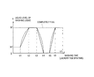
[0044] FIGS. 5 to 7 show an example of washing that combines a washing
operation by
simulated zero-gravity washing mode and a washing operation by impact washing
mode. The
vertical axis h in each graph is the liquid level in the laundry tub 2, and
the horizontal axis t is the
washing time, that is, the spin time of the laundry tub 2. The hf line that is
labeled as full
indicates a height that is higher than the highest level in the laundry tub 2,
that is, the height
when the laundry tub 2 has been completely filled with washing liquid.
[0045] In FIG. 5, the liquid level of the washing liquid supplied to the
laundry tub 2 is set low
so as to start from a washing operation by impact washing mode, and the value
of the liquid level
is hl. First, washing by impact washing mode is performed for a ti length of
time, and then the
washing liquid is continuously increased in the period from ti to t2 while the
laundry tub 2 is
spun. Consequently, the liquid level of washing liquid in the laundry tub 2
continuously
increases from hl to hf.
[0046] The effect of continuously increasing the liquid level of the washing
liquid while the
laundry tub 2 is spun as discussed above is that the liquid level is changed
from a washing step in
impact washing mode (impact washing step) until a washing step by simulated
zero-gravity
washing mode (simulated zero-gravity washing step). In this case, as discussed
above, the
system automatically switches from the impact washing step to the simulated
zero-gravity
washing step according to the liquid level of washing liquid, but there is an
intermediate liquid
level in which an intermediate washing operation in between impact washing
mode and
simulated zero-gravity washing mode comes into play via the above-mentioned
scrub washing
step. This is believed to be a state in which the laundry is suspended while
moving up and down
(this will be called butterfly washing). It is anticipated that adding this
washing operation to the
procedure will enhance the effect of removing stains from the laundry.
[0047] Washing is then performed in simulated zero-gravity washing mode in the
period from
t2 to t3, and then the washing liquid is drained to lower the lever in the
period from t3 to t4, and
the liquid level of the washing liquid in the laundry tub 2 is continuously
reduced from hf to 0.
Consequently, the process goes through the simulated zero-gravity washing step
and the scrub
washing step before reaching the impact washing step, so stains can be further
removed.
CA 02954860 2017-01-11
= [0048] In the example in FIG. 5, the liquid level of the washing liquid
is zero (all of the
washing liquid drained) in the period from 14 to t5. When the laundry tub is
spun in this state in
which there is no washing liquid present, the laundry tumbles over the bumpy
curved surfaces 22.
Consequently, if the laundry is made up of fibers, the warp and weft yarns of
the laundry fabric
can be properly arranged, so a smoothing effect can be obtained in which the
shape and texture
of the laundry are put in order.
[0049] As discussed above, the liquid level of washing liquid in the laundry
tub is continuously
increased or decreased between the impact washing step and the simulated zero-
gravity washing
step, which means that not only is washing performed by impact washing step
and simulated
zero-gravity washing step, but also by butterfly washing and scrub washing
that are intermediate
between these, so an extremely good stain removal effect can be obtained.
[0050] Also, in FIG. 5, after the laundry tub has been spun in a state in
which there is no
washing liquid present, washing liquid is supplied and the liquid level
continuously raised during
the period from t5 to t6, again going through impact washing, scrum washing,
and butterfly
washing, eventually reaching the simulated zero-gravity washing step, and the
simulated zero-
gravity washing is performed in the period from t6 to t7, which is the end.
Thus, the liquid level
of washing liquid is continuously and repeatedly increased and decreased
between the impact
washing step and the simulated zero-gravity washing step, so that washing is
repeatedly executed
in different washing modes, and this enhances the stain removal effect even
more.
[0051] When the liquid level of the washing liquid in the laundry tub is
varied during washing,
the process may start with either the impact washing step or the simulated
zero-gravity washing
step and end with the simulated zero-gravity washing step, or may start with
either the impact
washing step or the simulated zero-gravity washing step and end with the
impact washing step.
However, in order to smooth out the shape and texture of laundry (clothing,
etc.) whose shape
and texture have been mussed, and reduce the ironing time required after
washing, the final step
is preferably the simulated zero-gravity washing step. This is to take
advantage of the smoothing
effect had by the simulated zero-gravity washing step.
[0052] As shown by the solid lines or one-dot chain lines in FIG. 5, the
increase or decrease in
washing liquid in the laundry tub 2 may be linear (solid lines), or may be a
curve (one-dot chain
lines), or may be continuous. Furthermore, the increase or decrease in washing
liquid may be
16
CA 02954860 2017-01-11
intermittent, in which the increase or decrease is halted midway through the
process, and then
started again.
[0053] FIG. 6 is an example of a washing method in which the liquid level of
washing liquid
may be set low so as to form a layer of air at the upper part of the laundry
tub 2 when the laundry
is a type that has high buoyancy, such as a down jacket with a low specific
gravity. In this case,
there is no need for the laundry tub to be completely filled with washing
liquid, and the liquid
level is h3. An example is shown in which the liquid level is increased and
decreased
periodically along a sine curve between the liquid levels h3 and h2.
[0054] FIG. 7 is similar to FIG. 6 in that it is an example of when there is
no need for the
laundry tub to be completely filled with washing liquid, and the liquid level
is set at h5, but in
this example, the washing liquid is increased or decreased linearly over just
the range of h10 to
hll, in the region of liquid level in which butterfly washing is believed to
be performed, between
the liquid level h4 at which the impact washing step is executed and the
liquid level h5 at which
the simulated zero-gravity washing step is executed.
[DESCRIPTION OF THE REFERENCE NUMERALS]
[0055] 1 casing
2 laundry tub
3 door
4 rotational axis
drive mechanism
11 loading opening
12 liquid supply channel
13 air channel
14 liquid discharge channel
liquid level measurement pipe
16 pressure sensor
17, 18 flow control valve
19 interface component
controller
21 opening
22 bumpy curved surface
17
CA 02954860 2017-01-11
22a concave part
22b convex part
23 slit
25 baffle
18