Note: Descriptions are shown in the official language in which they were submitted.
CA 02955100 2017-01-12
WO 2016/025845
PCT/US2015/045298
BLENDER RINSE ASSEMBLY
BACKGROUND OF THE DISCLOSURE
1. Field of the Disclosure
[0001] The present disclosure relates generally to a blender assembly. More
particularly, the present disclosure relates to a blender assembly that has a
rinse function.
2. Description of Related Art
[0002] Beverages, for example, a smoothie drink, can require blending of
beverage ingredients including ice, flavor ingredients, and other solid or
liquid
ingredients during a blending cycle. Flavor ingredients include liquid flavor
ingredients, for example, fruit juice and chocolate syrup, and solid
ingredients,
for example, nutraceuticals, vitamins, herbs, spices, berries and other
fruits,
vegetables, such as spinach, celery, beets, tomatoes, cucumbers, or carrots,
or pieces of fruit, vegetables or candies, such as solid chocolate pieces,
apple
or orange segments, or cut up vegetables. Herbs such as mint, parsley,
sage, rosemary, thyme, and any other herbs. Spices such as cayenne,
cinnamon, curry, nutmeg and any other spices.
[0003] Many challenges are encountered during a blending cycle. For
blenders, for example, automatic Blend-in-cup machines, there is a need to
perform many functions. One function that exists is to rinse the blend
chamber, blades, cup cover, etc. after completion of a blending cycle and
before the next blending cycle occurs. This rinse is vital to ensure a
previous
1
CA 02955100 2017-01-12
WO 2016/025845
PCT/US2015/045298
product of a beverage is not mixed into the next consumer's cup to ensure
consumer gets their requested drink without cross product contamination. It is
desirable that such a rinse assembly minimizes the number of parts that
themselves also need periodic sanitizing.
[0004] Accordingly, it has been determined by the present disclosure, there is
a need for integration of the rinsing feature and a cup structural placement
feature. It has been further determined by the present disclosure that there
is
a need for a rinse assembly that minimizes the number of parts and that can
be easily maintained.
SUMMARY
[0005] A rinse assembly includes a grate having a frame forming a plurality of
apertures, and a conduit having a wall surrounding an interior cavity. The
conduit has a curved shaping with a plurality of holes through the wall. The
conduit and grate form a one-piece structure.
[0006] A rinse assembly is also provided that includes a conduit having a wall
surrounding an interior cavity. The conduit has a curved shaping with a
plurality of holes through the wall. The conduit has a first end having a
first
opening and a second end having a second opening. A first end cap is
connectable to the conduit. The first end cap has a first unlocked position in
which the first end cap is removable from the conduit and a first locked
position in which the first end cap is fixed to the conduit. A second end cap
is
connectable to the conduit. The second end cap has a second unlocked
2
CA 02955100 2017-01-12
WO 2016/025845
PCT/US2015/045298
position in which the second end cap is removable from the conduit and a
second locked position in which the second end cap is fixed to the conduit.
[0007] A rinse assembly is further provided that includes a conduit having a
wall surrounding an interior cavity. The conduit has a curved shape with a
plurality of holes through the wall. The wall of the conduit directly contacts
a
surface of a blend chamber in a blender.
[0008] The above-described and other advantages and features of the present
disclosure will be appreciated and understood by those skilled in the art from
the following detailed description, drawings, and appended claims.
BRIEF DESCRIPTION OF THE DRAWINGS
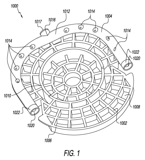
[0009] FIG. 1 is a top side perspective view of a first embodiment of a rinse
assembly according to the present disclosure.
[0010] FIG. 1A is a top side perspective view of an alternative shape of the
first embodiment of the rinse assembly.
[0011] FIG. 1B is a top front perspective view of the alternative shape of the
rinse assembly of FIG. 1A in a blender assembly.
[0012] FIG. 1C is a top front perspective view of the rinse assembly of FIG.
1B
having holes with a star shape in the blender assembly.
3
CA 02955100 2017-01-12
WO 2016/025845
PCT/US2015/045298
[0013] FIG. 2 is a top side perspective view of a blender assembly having the
rinse assembly of FIG. 1.
[0014] FIG. 3 is a front cross-sectional view of the blender assembly having
the rinse assembly of FIG. 1 showing a direction of water flow through holes
in the rinse assembly.
[0015] FIG. 4 is a side cross-sectional view of the blender assembly having
the rinse assembly of FIG. 1 showing the direction of water flow through the
holes in the rinse assembly.
[0016] FIG. 5 is an enlarged side cross-sectional view of a portion of the
blender assembly having the rinse assembly of FIG. 1.
[0017] FIG. 6 is an enlarged side cross-sectional view of a portion of the
blender assembly having the rinse assembly of FIG. 1 showing an open end
seal.
[0018] FIG. 7 is an enlarged side cross-sectional view of a portion of the
blender assembly having the rinse assembly of FIG. 1 showing an inlet end
seal.
[0019] FIG. 8 is a top cross-sectional view of the blender assembly having the
rinse assembly of FIG. 1.
[0020] FIG. 9 is an enlarged top cross-sectional view of a portion of the
blender assembly having the rinse assembly of FIG. 1 showing the inlet end
seal.
4
CA 02955100 2017-01-12
WO 2016/025845
PCT/US2015/045298
[0021] FIG. 10 is an enlarged top cross-sectional view of a portion of the
blender assembly having the rinse assembly of FIG. 1 showing the open end
seal.
[0022] FIG. 11 is a top side perspective view of the rinse assembly of FIG. 1
having an upper portion removed.
[0023] FIG. 12 is a bottom side perspective view of the rinse assembly of FIG.
1 having a lower portion removed.
[0024] FIG. 13 is a top side perspective view of the inlet end seal.
[0025] FIG. 14 is an enlarged partial top side perspective view of the rinse
assembly of FIG. 1 showing the inlet end seal.
[0026] FIG. 15 is a top side perspective view of the open end seal.
[0027] FIG. 16 is an enlarged partial top side perspective view of the rinse
assembly of FIG. 1 showing the open end seal.
[0028] FIG. 17A is an enlarged partial side cross-sectional view of the rinse
assembly of FIG. 1 showing one of the holes.
[0029] FIG. 17AA is an enlarged partial side cross-sectional view of the rinse
assembly of FIG. 1 showing one of the holes having an adjustable jet.
[0030] FIG. 17A' is a top front perspective view of the rinse assembly of FIG.
1
showing the holes having adjustable jets in the blender assembly.
CA 02955100 2017-01-12
WO 2016/025845
PCT/US2015/045298
[0031] FIG. 17A" is an enlarged partial side cross-sectional view of the rinse
assembly of FIG. 1 showing one of the holes having the adjustable jet.
[0032] FIG. 17B is top side perspective view of an alternative rinse assembly
of the present disclosure having an insert.
[0033] FIG. 17C is top side perspective view of the alternative rinse assembly
of FIG. 17B having the insert removed.
[0034] FIG. 17D is top side perspective view of the insert of FIG. 17B.
[0035] FIG. 17E is a bottom side perspective view of an upper portion of the
alternative rinse assembly of FIG. 17B.
[0036] FIG. 17EE is a top side perspective view of the upper portion of the
alternative rinse assembly of FIG. 17B.
[0037] FIG. 17E' is a top side perspective view of a lower portion of the
alternative rinse assembly of FIG. 17B.
[0038] FIG. 17F is an enlarged side cross-sectional view of a portion of a
blender assembly having the alternative rinse assembly of FIG. 17B.
[0039] FIG. 17G is an enlarged side cross-sectional view of a portion of a
blender assembly having the alternative rinse assembly of FIG. 17B.
[0040] FIG. 17H is an enlarged front top side perspective view of a spring
keeper assembly of the alternative rinse assembly of FIG. 17B.
6
CA 02955100 2017-01-12
WO 2016/025845
PCT/US2015/045298
[0041] FIG. 171 is an enlarged rear top side perspective view of the spring
keeper assembly of the alternative rinse assembly of FIG. 17B.
[0042] FIG. 17J is an enlarged front top side perspective view of a spring of
the alternative rinse assembly of FIG. 17B.
[0043] FIG. 18 is a top side perspective view of a second embodiment of a
rinse assembly according to the present disclosure.
[0044] FIG. 18A is a top side perspective view of an alternative shape of the
second embodiment of the rinse assembly.
[0045] FIG. 19 is a top side perspective view of a blender assembly having the
rinse assembly of FIG. 18.
[0046] FIG. 20 is a front cross-sectional view of the blender assembly having
the rinse assembly of FIG. 18 showing a direction of water flow through holes
in the rinse assembly.
[0047] FIG. 21 is an enlarged side cross-sectional view of a portion of the
blender assembly having the rinse assembly of FIG. 18.
[0048] FIG. 22 is an enlarged side cross-sectional view of a portion of the
blender assembly having the rinse assembly of FIG. 18 showing an open end
seal with a cap.
[0049] FIG. 23 is an enlarged side partial cross-sectional view of the rinse
assembly of FIG. 18 showing the open end seal with the cap.
7
CA 02955100 2017-01-12
WO 2016/025845
PCT/US2015/045298
[0050] FIG. 24 is an enlarged side cross-sectional view of a portion of the
blender assembly having the rinse assembly of FIG. 18 showing an inlet end
seal.
[0051] FIG. 25 is an enlarged top cross-sectional view of a portion of the
blender assembly having the rinse assembly of FIG. 18.
[0052] FIG. 26 is an enlarged top cross-sectional view of a portion of the
blender assembly having the rinse assembly of FIG. 18 showing the inlet end
seal.
[0053] FIG. 27 is an enlarged top cross-sectional view of a portion of the
blender assembly having the rinse assembly of FIG. 18 showing the open end
seal with the cap.
[0054] FIG. 28 is a bottom side perspective view of the rinse assembly of FIG.
18 having an upper portion removed.
[0055] FIG. 29 is a bottom side perspective view of the rinse assembly of FIG.
18 having a lower portion removed.
[0056] FIG. 30A is an enlarged side cross-sectional view of the cap.
[0057] FIG. 30B is an enlarged bottom side perspective view of the cap.
[0058] FIG. 31A is an enlarged partial side cross-sectional view of the rinse
assembly of FIG. 18 showing the open end seal with the cap.
8
CA 02955100 2017-01-12
WO 2016/025845
PCT/US2015/045298
[0059] FIG. 31B is an enlarged partial rear cross-sectional view of the rinse
assembly of FIG. 18 showing the open end seal with the cap.
[0060] FIG. 32 is an enlarged partial side cross-sectional view of the rinse
assembly of FIG. 18 showing one of the holes.
[0061] FIG. 32A is an enlarged partial side cross-sectional view of the rinse
assembly of FIG. 18 showing one of the holes having an adjustable jet.
[0062] FIG. 33 are top side perspective views of another rinse assembly, the
rinse assembly of FIG. 18 and the rinse assembly of FIG. 17B.
[0063] FIG. 34 is a top side perspective view of a third embodiment of a rinse
assembly according to the present disclosure.
[0064] FIG. 34A is a top side perspective view of a blender assembly having
rinse assembly of FIG. 34 having an alternative shape.
[0065] FIG. 35 is a top side perspective view of a blender assembly having a
fourth embodiment of a rinse assembly according to the present disclosure.
[0066] FIG. 35A is a top side perspective view of a blender assembly having
rinse assembly of FIG. 35.
[0067] FIG. 35A' is a top side cross-sectional view of the rinse assembly of
FIG. 35A.
[0068] FIG. 36 is an enlarged side cross-sectional view of a portion of a
blender assembly having a fifth embodiment of a rinse assembly according to
the present disclosure.
9
CA 02955100 2017-01-12
WO 2016/025845
PCT/US2015/045298
[0069] FIG. 36A is a side front view of a portion of the blender assembly
having the rinse assembly of FIG. 36.
[0070] FIG. 37 is a top side perspective view of a portion of a blender
assembly having a sixth embodiment of a rinse assembly according to the
present disclosure.
[0071] FIG. 37A is a top front perspective view of a portion of a blender
assembly with a portion of the side wall removed having the rinse assembly of
FIG. 37.
[0072] FIG. 38 is a top side perspective view of a portion of a blender
assembly having a seventh embodiment of a rinse assembly according to the
present disclosure.
[0073] FIG.38A is a top front perspective view of a portion of a blender
assembly having the rinse assembly of FIG. 38 having a conduit with an
alternative shape.
[0074] FIG. 39 is a front cross-sectional view of a portion of a blender
assembly having an eighth embodiment of a rinse assembly according to the
present disclosure.
DETAILED DESCRIPTION OF THE DISCLOSURE
[0075] Referring to the drawings and in particular to FIG. 1, an exemplary
embodiment of a rinse assembly of the present disclosure is generally
referred to by 1000. Rinse assembly 1000 has a grate 1002 and a conduit
CA 02955100 2017-01-12
WO 2016/025845
PCT/US2015/045298
1004 formed as a one-piece structure. Grate 1002 has frame members 1006
that form openings 1008 through grate 1002. Grate 1002 has a support
member 1010 that extends outward from frame members 1006. Support
member 1010 is shaped complementary to a container, for example, a plastic
or Styrofoam cup, in which blending of a beverage takes place. Conduit 1004
has a wall 1012 and holes 1014 through wall 1012. Conduit 1004 has a
sidewall 1016 that surrounds a connection aperture (shown in FIG. 4) 1018.
Sidewall 1016 is connectable to a water source. Sidewall 1016 is connected
to an inlet end seal 1017. Inlet end seal 1017 is overmolded onto conduit
1004. Conduit 1004 has open ends 1020. Each of open ends 1020 is
connected to one of open end seals 1022. Open end seals 1022 each have
an opening so that each of open ends 1020 is not covered by open end seals
1022 and each of open ends 1020 remains open. Open ends 1020 and open
end seals 1022 are identical. Alternatively, as shown in FIGS. 1A-1B, conduit
1004 is a shape that surrounds the perimeter of grate 1002 or a side wall
5004 of a blender 5000, for example a circle-like shape, said shape omitting
open ends 1020 and open end seals 1022. Holes 1014 each are located
around a perimeter of conduit 1004 to direct in water in predetermined
directions. Pressurized water received through sidewall 1016 flows out of
holes 1014 to form a spray 1011 around the perimeter of grate 1002 in the
predetermined directions.
[0076] Referring to FIG. 2, rinse assembly 1000 may be incorporated into a
blender 5000, for example, blender/mixer/cleaning module 303 that is a part
of an assembly that dispenses and mixes beverages as described in U.S.
Patent Application Serial No. 12/633,790, filed December 8, 2009, the
contents of which are incorporated herein by reference in its entirety.
Blender
11
CA 02955100 2017-01-12
WO 2016/025845
PCT/US2015/045298
5000 has a blender chamber 5002. Blender chamber 5002 has a side wall
5004 and a base wall 5006. Base wall 5006 has retaining walls 5007a and
5007b. Base wall 5006, side wall 5004 and retaining walls 5007a and 5007b
have a shape that is complementary to rinse assembly 1000 so that rinse
assembly 1000 is maintained in a stationary position. Blender 5000 has a
blender cover 5008 that covers a blender blade 5010 (FIG. 4). Blender blade
5010 is rotated by a spindle 5012 (FIG. 4) that may be covered by a spindle
cover 5014. Blender 5000 also has a container cover 5016 that covers the
container in which blending of a beverage takes place.
[0077] Referring to FIG. 3, in use, water is supplied under pressure to rinse
assembly 1000 forming streams, as shown by arrows 1024, 1026, 1028,
1030, 1032, 1034, 1038, 1040, of water through each of holes 1014 through
conduit 1004. Holes 1014 are shaped so that each of streams 1024, 1026,
1028, 1030, 1032, 1034, 1038, 1040 are directed in predetermined directions
to rinse blender 5000 with water. As shown in FIG. 1, each of holes 1014 is
located around a perimeter of conduit 1004 also to direct in water in
predetermined directions. Holes 1014 can be shapes, such as, for example,
circles, ovals, rectilinear, trapezoidal, triangular, stars. FIG. 1C shows
holes
1014 having a star shape forming a spray 1011. Holes 1014 can have
different or the same shapes. Streams 1024 and 1034 are directed to
container cover 5016. Streams 1026 and 1036 are directed to side wall 5004.
Streams 1028 and 1038 are directed to an outside of blender cover 5008.
Streams 1030 and 1040 are directed to an inside of blender cover 5008.
Stream 1032 is directed to blender blade 5010. The water falls through grate
1002 by gravity into a sump cavity 5018 formed by a sump wall 5019. Sump
cavity 5018 is connected to a drain pipe 5020 of blend chamber 5002 to drain
12
CA 02955100 2017-01-12
WO 2016/025845
PCT/US2015/045298
water from blender 5000. The water may be mixed with sanitizer.
Alternatively, streams, as shown by arrows 1024, 1026, 1028, 1030, 1032,
1034, 1038, 1040, of water through each of holes 1014 through conduit 1004
can be pulsed and not a continuous flow. A pump or modulator can pulse the
flow of water through each of holes 1014 through conduit 1004. Another
alternative, streams, as shown by arrows 1024, 1026, 1028, 1030, 1032,
1034, 1038, 1040, of water through each of holes 1014 through conduit 1004
can use a combination of water and air from a source of pressurized air. The
water can also include cleaning or sanitizing fluid.
[0078] Referring to FIG. 4, when rinse assembly 1000 is in place in blend
chamber 5002, inlet end seal 1017 contacts side wall 5004 to align connection
aperture 1018 and an inlet opening 5022 through side wall 5004. Inlet
opening 5022 communicates with water source tubing 6000 to provide a flow
of water, as shown by arrow 6002, through inlet aperture 5022 and connection
aperture 1018 into passage 1021 of conduit 1004. Passage 1021 is
continuous between open ends 1020. When rinse assembly 1000 is in place
in blend chamber 1002, each of open end seals 1022 contacts one of
retaining walls 5007a and 5007b forming a seal between each of open end
seals 1022 and one of retaining walls 5007a and 5007b closing open ends
1020 so that water flows through holes 1014 out of conduit 1004. Conduit
1004 may form additional streams 1042, 1044, 1046 and 1048 through holes
1014.
[0079] Referring to FIGS. 5-10, inlet end seal 1017 and one of open end seals
1022 are shown in pre-state manufactured position when rinse assembly
1000 is not positioned in blender. However, inlet end seal 1017 and open end
seals 1022 will be compressed so that inlet end seal 1017 contacts side wall
13
CA 02955100 2017-01-12
WO 2016/025845
PCT/US2015/045298
5004 and open end seals 1022 contact one of retaining walls 5007a and
5007b when in place in blender 5000. Inlet end seal 1017 has a protrusion
1050 that fits in groove 1052 in side wall 1016 connecting inlet end seal 1017
to side wall 1016. Inlet end seal 1017 may be removable from side wall 1016.
Inlet end seal 1017 has a groove 1054 forming a fold 1056. Fold 1056 is
moved toward side wall 1016 when inlet end seal 1017 is compressed. Fold
1056 has a ridge 1058 that may be urged against side wall 5004 when inlet
end seal 1017 is compressed. Open end seals 1022 each has a protrusion
1060 that fits in groove 1063 in conduit 1004 connecting open end seals 1022
to conduit 1004. Open end seals 1022 may be removable from conduit 1004.
[0080] Referring to FIGS. 11-12, rinse assembly 1000 has a lower portion
1062 and an upper portion 1064. Upper portion 1064 has a channel 1066 and
lower portion 1062 has a channel 1068. Upper portion 1064 and lower portion
1062 are connected to form conduit 1004. When upper portion 1064 and
lower portion 1062 are connected, channels 1066 and 1068 are aligned to
form passage 1021. Lower portion 1062 is connected to upper portion 1064,
for example, by snap fit, adhesive, molding, and/or thermoplastic welding
such as ultrasonic welding, hot plate welding, vibration welding, etc..
[0081] Referring to FIGS. 13-14, inlet end seal 1017 has a side portion 1070
that surrounds side wall 1016. Side portion 1070 is shaped to extend beyond
side wall 1016 on a top portion 1072. Inlet end seal 1017 has an interior wall
1074 that extends into connection aperture 1018. Inlet end seal 1017 is made
of a material, for example, plastic such as thermoplastic elastomer, or
natural
rubber. Inlet end seal 1017 may be overmolded onto side wall 1016 or
manufactured as a separate part and assembled onto side wall 1016.
14
CA 02955100 2017-01-12
WO 2016/025845
PCT/US2015/045298
[0082] Referring to FIGS. 15-16, open end seals 1022 each have a forward
portion 1076 that extends away from conduit 1004. Front portion 1076 has an
aperture 1078 that is wider than open ends 1020. Open end seals 1022 are
made of a material, for example, plastic such as thermoplastic elastomer, or
rubber. Open end seals 1022 may be overmolded onto conduit 1004 or
manufactured as a separate part and assembled onto conduit 1004.
[0083] Referring to FIG. 17A, a portion 1080 of conduit 1004 surrounding each
of holes 1014 is shaped to direct water that passes through holes 1014 in
predetermined directions. For example, a conical shape may surround each
of holes 1014. Each of holes 1014 is located on conduit 1004, e.g., closer to
grate 1002 or further from grate 1002, to direct in water in predetermined
directions. Alternatively, as shown in FIGS. 17AA-17A", each of holes 1014
has an adjustable jet. The adjustable jet, for example, has an adjustable body
1041 that is generally spherical in shape having an orifice 1041a through
adjustable body 1041. Adjustable body 1041 can be moved, for example,
along arrow AA, by placing a tool or pin inside of orifice 1041a and applying
a
pressure in the desirable direction moving adjustable body 1041 until orifice
1041a is positioned in a desired position so that pressurized water through
orifice 1041a form a spray in a desired direction as shown by arrow 1011a.
Adjustable body 1041 may connect to conduit 1004 inside of one or more of
holes 1014 by friction or snap fit forming a ball and socket connection.
Alternatively, conduit 1004 may be a hollow annulus that distributes water to
holes 1014.
[0084] To further enable a rinsing operation the container in which blending
takes place needs to be separated from blender chamber 5002 with grate
1002. Grate 1002 suspends the container in which blending takes place in
CA 02955100 2017-01-12
WO 2016/025845
PCT/US2015/045298
space sufficiently to provide a sump cavity 1002 in the blender chamber 5002.
In addition to suspending the container in which blending takes place above
the sump cavity 5018, grate 1002 must also robustly handle a reaction loading
that occurs during a blending operation. Grate 5018 is made of a material, for
example, thermoplastic. Rinse assembly 1000 integrates grate 1002 with
rinsing components such as conduit 1004. Integrating conduit 1004 with grate
1002 aligns and levels conduit 1004 in blender chamber 5002 upon
placement of grate 1002 in blender chamber increasing ease of installation of
conduit 1004. The one-piece structure of grate 1002 and conduit 1004
decreases cost over separate grates and conduits and permits rinse assembly
1000 to be moldable. Molding rinse assembly 1000 decreases or eliminates
inconsistencies created by second tooling, for example, if there was a need
for drilling holes 1014. Rinse assembly 1000 may be used with a pressure
booster.
[0085] The integration of rinsing feature and cup structural placement feature
is achieved by rinse assembly 1000. Rinse assembly 1000 can be easily
removed by customer for daily/weekly cleaning operation(s). Once rinse
assembly 1000 is removed blender chamber 5002 can be thoroughly cleaned
while in place in the blender. While rinse assembly 1000 is removed rinse
assembly 1000 can be placed into bucket of cleaning solution to soak. Rinse
assembly 1000 enables conduit 1004 to be cleaned with a nylon brush
between open ends 1020. There is one continuous passage 1021 that can be
cleaned with the nylon brush.
[0086] Referring to FIG. 17B, an alternative embodiment of a rinse assembly
is shown and generally referred to by 1500. Rinse assembly 1500 is similar to
16
CA 02955100 2017-01-12
WO 2016/025845
PCT/US2015/045298
rinse assembly 1000. Features that are the same in rinse assembly 1500 and
rinse assembly 1000 are referred to by the same reference numerals. Rinse
assembly 1500 has side wall 1516 of conduit 1504. Side wall 1516 has a
groove 1561.
[0087] Rinse assembly 1500 has a grate 1502 with frame members 1506 that
form openings 1508 through grate 1002. Grate 1502 has a grate support
member 1510 that extends outward from frame members 1506. Grate
support member 1510 is shaped complementary to a container, for example,
a plastic or Styrofoam cup, in which blending of a beverage takes place, or to
fit an insert 1563. Insert 1563 can be removable from grate 1502. Insert
1563 may fit in grate support member 1510 to rest on frame members 1506
by gravity or be secured to frame members 1506, for example, by friction fit
or
snap fit. Insert 1563 is shaped complementary to a container, for example, a
plastic or Styrofoam cup.
[0088] Referring to FIG. 17C, grate 1502 has connectors 1565. Each of
connectors 1565 has an outer frame 1567 and a frame opening 1569.
[0089] Referring to FIG. 17D, insert 1563 has an outer member 1571. Outer
member 1571 is shaped complementary to grate support member 1510 so
that insert 1563 fits in grate support member 1510. Insert 1563 has an insert
support member 1573. Insert support member 1573 is shaped complementary
to a container, for example, a plastic or Styrofoam cup, in which blending
takes place. Insert 1563 has indentations 1575 that are sized to each receive
outer frame 1567 of one of connectors 1565 to maintain insert 1563 in place
in grate support member 1510. Insert 1563 has protrusions 1576 that each fit
in one of frame openings 1569. Grate 1502 may be used with different rings
17
CA 02955100 2017-01-12
WO 2016/025845
PCT/US2015/045298
1563 that each has a different ring support member 1573 to support a
different sized container. The different inserts 1563 each has the same outer
member 1571 to each fit in grate support member 1510. Insert 1563 provides
centering alignment of the container, e.g., cup, in the blender 5000. Insert
1563 is custom to each customer and is easily removed and snapped into
place so that another cup insert of different size for a different customer
may
be used.
[0090] Referring to FIGS. 17E, 17EE and 17E', rinse assembly 1500 has a
lower portion 1562 (FIGS. 17E' and 17F) and an upper portion 1564 (FIGS.
17E and 17EE). Upper portion 1564 has a channel 1566 and lower portion
1562 has a channel 1568. Upper portion 1564 and lower portion 1562 are
connected to form conduit 1504. When upper portion 1564 and lower portion
1562 are connected, channels 1566 and 1568 are aligned to form passage
1021. Lower portion 1562 is connected to upper portion 1564, for example,
by snap fit, adhesive, molding and/or thermoplastic welding such as ultrasonic
welding, hot plate welding, vibration welding, etc.. Upper portion 1564 has
open end seals 1022 and groove 1561 so that all of the seal geometry is on
upper portion 1564. Groove 1561 is sized to receive an o-ring seal so that a
seal is not overmolded onto side wall 1516.
[0091] Referring to FIG. 17F, side wall 5004 of blender 5000 forms a cavity
5552 accessed by a cavity opening 5554. Cavity 5552 is sized to receive
sidewall 1516. A spring 7100, as shown in FIG. 17J, is between side wall
1516 of rinse assembly 1500 and side wall 5004 of blender 5000 in cavity
5552. Spring 7100 is shown in pre-state manufactured position when rinse
assembly 1500 is not positioned in blender. However, spring 7100 will be
compressed between side wall 1516 and side wall 5004 of blender 5000 when
18
CA 02955100 2017-01-12
WO 2016/025845
PCT/US2015/045298
in place in blender 5000. Spring 7100 provides compression to open end
seals 1022 against retaining walls 5007a and 5007b when rinse assembly
1500 is in blender 5000. As shown in FIGS. 17H and 171, spring 7100 may be
housed in spring keeper assembly 7102. Spring keeper assembly 7102 has a
downstream portion 7104 and an upstream portion 7106. Downstream
portion 7104 abuts side wall 1516 and has an opening 7108 that aligns with
connection aperture 1018. Cavity 5552 narrows in size adjacent upstream
portion 7106 so that upstream portion 7106 abuts side wall 5004 of blender
5000 in cavity 5552. Upstream portion 7106 has an opening 7110 that aligns
with opening 7108 and connection aperture 1018 so that water may pass
therethrough. Downstream portion 7104 fits in upstream portion 7106.
Spring 7100 urges upstream portion 7106 and downstream portion 7104
apart. Upstream portion 7106 has one or more apertures 7112. Downstream
portion 7104 has one or more ridges 7114 that fit in apertures 7110 to
maintain a connection between upstream portion 7106 and downstream
portion 7104.
[0092] Referring to FIG. 17G, cavity 5552 is sized to receive sidewall 1516 so
that a side wall seal 1517 is between sidewall 1516 and side wall 5004 in
cavity 5552. Side wall seal 1517 is an o-ring seal forming a radial hydraulic
seal.
[0093] Referring to FIG. 18, a second embodiment of a rinse assembly of the
present disclosure is generally referred to by 2000. Features of rinse
assembly 2000 that are the same as rinse assembly 1000 have the same
reference numerals. Rinse assembly 2000 has a conduit 2004. Conduit 2004
has caps 2100 connected to ends 2105 and 2107 of conduit 2004. Ends
2105 and 2107 have conduit openings 21 16 and 2118, as shown in FIG. 29.
19
CA 02955100 2017-01-12
WO 2016/025845
PCT/US2015/045298
Caps 2100 closed ends 2105 and 2107 of conduit 2004. Conduit 2004 has a
wall 2012 and holes 2014 through wall 2012. Conduit 2004 has a sidewall
2016 that surrounds a connection aperture (shown in FIG. 21) 2018. Sidewall
2016 is connectable to a water source. Sidewall 2016 is connected to an inlet
end seal 2017, for example, an o-ring seal. Conduit 2004 has a protuberance
2102 extending outward from sidewall 2016. Alternatively, as shown in FIG.
18A, conduit 2004 is a circle shape omitting conduit openings 2116 and 2118
and caps 2100.
[0094] Referring to FIG. 19, rinse assembly 2000 may be incorporated into a
blender 5000, for example, blender/mixer/cleaning module 303 that is a part
of an assembly that dispenses and mixes beverages as described in U.S.
Patent Application Serial No. 12/633,790, filed December 8, 2009, the
contents of which are incorporated herein by reference in its entirety.
Blender
5000 has base wall 5006 with a grate 5005 that is separate from rinse
assembly 2000. Side wall 5004 has brackets 5050 that each attach to conduit
2004 by snap fit.
[0095] Referring to FIG. 20, in use, conduit is connected to blend chamber
5002. At least a portion of conduit 2004 contacts side wall 5004 of blend
chamber 5002. Water is supplied under pressure to rinse assembly 2000
forming streams, as shown by arrows 2024, 2026, 2028, 2030, 2032, 2034, of
water through each of holes 2014 through conduit 2004. Holes 2014 are
shaped and located so that each of streams 2024, 2026, 2028, 2030, 2032,
2034 are directed in predetermined directions to rinse blender 5000 with
water. Streams 2026, 2028, 2030, 2032, are directed to container cover
5016. Streams 2024 and 2034 are directed to blender cover 5008. Holes
CA 02955100 2017-01-12
WO 2016/025845
PCT/US2015/045298
2014 can be shapes, such as, for example, circles, ovals, rectilinear,
trapezoidal, triangular, stars. Holes 2014 can have different or the same
shapes. The water falls through grate 5005 by gravity into sump cavity 5018
of formed by sump wall 5019. Sump cavity 5018 is connected to drain pipe
5020 of blend chamber 5002 to drain water from blender 5000. The water
may be mixed with sanitizer. Alternatively, streams, as shown by arrows 2024,
2026, 2028, 2030, 2032, 2034, of water through each of holes 2014 through
conduit 2004 can be pulsed and not a continuous flow. A pump or modulator
can pulse the flow of water through each of holes 2014 through conduit 2004.
Another alternative, streams, as shown by arrows 2024, 2026, 2028, 2030,
2032, 2034, of water through each of holes 2014 through conduit 2004 can
use a combination of water and air from a source of pressurized air. The
water can also include cleaning or sanitizing fluid.
[0096] Referring to FIGS. 21, 24 and 26, side wall 5004 forms a cavity 5052
accessed by a cavity opening 5054. Cavity 5052 is sized to receive sidewall
2016 so that inlet end seal 2017 forms a seal between sidewall 2016 and side
wall 5004 in cavity 5052. Protuberance 2102 contacts side wall 5004 to limit
movement of side wall 2016 into cavity 5052. Surface of side wall 5004
forming cavity 5052 supports conduit 2004. When rinse assembly 2000 is in
place in blender chamber 5002, inlet end seal 2017 contacts side wall 5004 to
align connection aperture 2018 and an aperture 5056 through side wall 5004.
Aperture 5056 communicates with a water source to provide a flow of water
through aperture 5056 and connection aperture 2018 into a passage 2021 of
conduit 2004. Passage 2021 is continuous between ends 2105 and 2107 of
conduit 2004. Alternatively, brackets 5050 may be omitted, and conduit 2004
21
CA 02955100 2017-01-12
WO 2016/025845
PCT/US2015/045298
may be connected to blender chamber by connection of sidewall 2016 and
side wall 5004 in cavity 5052.
[0097] Referring to FIGS. 22 and 27, conduit 2004 has two conduit apertures
2101 and 2103 adjacent two end walls 2111 and 2113 that extend outward
from passage 2021. Caps 2100 are identical. Each of end caps 2100 has a
cover portion 2106 and connection portion 2108. Cover portion 2106 is sized
to enclose ends 2105 and 2107. Connection portion 2108 fits in conduit 2004.
A cap seal 2110 is between connection portion 2108 and conduit 2004
forming a seal between connection portion 2108 and conduit 2004. The seal
is between connection portion 2108 and conduit 2004 so that water passes
through sidewall 2016 through passage 2021 and out of holes 2014 forming
streams 2024, 2026, 2028, 2030, 2032, 2034. Cover portion 2106 of each of
caps 2100 is adjacent end walls 2111 and 2113 of conduit 2004 when caps
2100 are connected to conduit 2004.
[0098] Referring to FIG. 23, caps 2100 have two protrusions 2112 and 2114.
Each of protrusions 2112 and 2114 fits through one of conduit apertures 2101
and 2103 through conduit 2004. Alternatively, wall 2012 of conduit 2004 may
be continuous having depressions in passage 2021 that receive protrusions
2112 and 2114 instead of protrusions 2112 and 2114 passing through conduit
apertures 2101.
[0099] Referring to FIG. 25, side wall 5004 may have protruding portions 5064
and 5066 that abut conduit 2004. Protruding portions 5064 and 5066 support
conduit 2004 to maintain conduit 2004 in place in blender chamber 5002.
22
CA 02955100 2017-01-12
WO 2016/025845
PCT/US2015/045298
[00100] Referring to FIGS. 28-29, rinse assembly 2000 has a lower
portion 2062 and an upper portion 2064. Upper portion 2064 has a channel
2066 and lower portion 2062 has a channel 2068. Upper portion 2064 and
lower portion 2062 are connected to form conduit 2004. When upper portion
2064 and lower portion 2062 are connected, channels 2066 and 2068 are
aligned to form passage 2021.
[00101] Referring to FIGS. 30a-31b, caps 2100 are rotatable in opposite
directions, as shown by arrows 2120, when in conduit 2004 between an
unlocked position, and, as shown in FIG. 31b, a locked position. For example,
caps 2100 may be rotated 60 degrees between the unlocked position and
locked position. Conduit 2004 forms grooves 2022 in each of end walls 2111
and 2113.
[00102] In use, protrusion 2112 is aligned with one of grooves 2022 in
end wall 2111 so that protrusion 2112 passes through one of grooves 2022 in
end wall 2111 in the unlocked position and protrusion 2114 is aligned with one
of grooves 2022 in end wall 2113 so that protrusion 2114 passes through one
of grooves 2022 in end wall 2113 in the unlocked position. Caps 2100 are
rotated moving protrusion 2112 in conduit aperture 2101 out of alignment with
one of grooves 2022 in end wall 2111 to the locked position and protrusion
2114 is moved in conduit aperture 2103 out of alignment with one of grooves
2022 in end wall 2113 to the locked position. In the locked position, if an
attempt is made to move one of caps 2100 out of conduit 2004, protrusions
2112 and 2114 would contact wall 2012 of conduit 2004 preventing removal of
caps 2100. When in the locked position, caps 2100 are rotated moving
protrusion 2112 in conduit aperture 2101 into of alignment with one of grooves
2022 in end wall 2111 to the unlocked position and protrusion 2114 is moved
23
CA 02955100 2017-01-12
WO 2016/025845
PCT/US2015/045298
in conduit aperture 2103 into alignment with one of grooves 2022 in end wall
2113 to the unlocked position. In the unlocked position, protrusion 2112
passes through one of grooves 2022 in end wall 2111 and protrusion 2114
passes through one of grooves 2022 in end wall 2113 to remove each of caps
2100 from conduit 2004. Rinse assembly 2000 prevents unintended removal
of caps 2100 by establishing a locked position. Accordingly, caps 2100 will
not be lost.
[00103] Referring to FIG. 32, a portion 2080 of conduit 2004 surrounding
each of holes 2014 is shaped to direct in water that passes through holes
2014 in predetermined directions. For example, a conical shape may
surround each of holes 2014. Each of holes 2014 is located around a
perimeter of conduit 2004 to direct in water in predetermined directions.
Alternatively, as shown in FIG. 32A, each of holes 2014 has an adjustable jet.
The adjustable jet, for example, has an adjustable body 2041 that is spherical
in shape having an orifice 2041a through adjustable body 2041. Adjustable
body 2041 can be moved, for example, along arrow AA, by placing a tool or
pin inside of orifice 2041a and applying a pressure in the desirable direction
moving adjustable body 2041 until orifice 2041a is positioned in a desired
position. Adjustable body 2041 may connect to conduit 2004 inside of one or
more of holes 2014 by friction or snap fit.
[00104] FIG. 33 are top side perspective views of another rinse
assembly 3000, rinse assembly 2000 of FIG. 18 and rinse assembly 1500 of
FIG. 17b.
[00105] FIGS. 34-34A show another embodiment of a rinse assembly
4000. Rinse assembly 4000 has a grate 4002 to support a beverage
24
CA 02955100 2017-01-12
WO 2016/025845
PCT/US2015/045298
container. Grate 4002 has frame members 4006 that form openings 4008
through grate 4002. Grate 4002 has a support member 4010 that extends
outward from frame members 4006. Support member 4010 is shaped
complementary to a container, for example, a plastic or Styrofoam cup, in
which blending of a beverage takes place. Grate 4002 has a sidewall 4016
that surrounds a connection aperture 4018 therein. Sidewall 4016 is
connected to an inlet end seal 4017. Inlet end seal 4017 is overmolded onto
conduit sidewall 4016. Sidewall 4016 is connectable to a water source.
Connection aperture 4018 is connected to conduits 4003 that are inside of
grate 4002 that connect to holes 4014 through grate 4002. Conduits 4003 are
formed by a dual wall structure. Holes 4014 may be shaped to direct water
each in a predetermined direction. Rinse assembly 4000 may be
incorporated into a blender 5000 similar to rinse assembly 1000 so that when
rinse assembly 4000 is in place in blend chamber 5002, inlet end seal 4017
contacts side wall 5004 to align connection aperture 4018 and inlet opening
5022 through side wall 5004 and inlet opening 5022 communicates with water
source. Water provided under pressure flows through inlet opening 5022 to
connection aperture 4018 to conduits 4003 and out of holes 4014 to form a
spray 4011 to spray blender chamber 5002 in the predetermined direction.
FIGS. 34-34A show alternative shapes of grate 4002.
[00106] FIGS. 35-35A' show another embodiment of a rinse assembly
6000. Rinse assembly 6000 is incorporated into container cover 5016 of
blender 5000. Container cover 5016 has holes 6014 along its upper surface,
lower surface (not shown) and/or side surfaces. Holes 6014 may be shaped
to direct water each in a predetermined direction. A manifold 6005 formed by
a first wall 6005a and second wall 6005b forming a dual wall structure or
CA 02955100 2017-01-12
WO 2016/025845
PCT/US2015/045298
separate conduits each for one of holes 6014 connect holes 6014 to a conduit
6003. Conduit 6003 connects to a water source so that water provided under
pressure flows through conduit 6003 to a cavity in manifold 6005 and out of
holes 6014 to form a spray 6011 to spray blender chamber 5002 in the
predetermined direction. As in previous embodiments, the holes can have
various shapes and/or incorporate adjustment jet spray heads, and/or use
continuous or pulsating streams of water, said water which may include
cleaning or sanitizing fluid. Container cover 5016 is movable by a telescoping
member 6077 that extends and retracts to move container cover 5016.
Conduit 6003 may have a telescoping structure similar to telescoping member
6077 to extend and retract with the movement of telescoping member 6077.
[00107] FIGS. 36-36A show another embodiment of a rinse assembly
7000. Rinse assembly 7000 is incorporated into sump cavity 5018 of blender
5000. Sump cavity 5018 has holes 7014 through a first wall 7003a. Holes
7014 may be shaped to direct water each in a predetermined direction. First
wall 7003a forms a manifold 7005 with a second wall 7003b to form a dual
wall structure. Manifold 7005 connects to a water source by conduit 7009 so
that water provided under pressure flows through manifold 7005 to holes 7014
forming a spray 7011 to spray blender chamber 5002 in the predetermined
direction. Alternatively, separate conduits for each of one of holes 7014
connect holes 7014 to conduit 7009. A grate may be placed above sump
cavity 5018 to support a beverage container.
[00108] FIGS. 37-37A show another embodiment of a rinse assembly
8000. Rinse assembly 8000 is incorporated into side wall 5004 of blender
5000. Blender 5000 has holes 8014 through side wall 5004. Holes 8014 may
be shaped to direct water each in a predetermined direction. First wall 8003
26
CA 02955100 2017-01-12
WO 2016/025845
PCT/US2015/045298
forms a manifold 8005 with side wall 5004 forming a dual wall structure.
Manifold 8005 connects to a water source by conduit 8009 so that water
provided under pressure flows through an inner cavity of manifold 8005 to
distribute the water to holes 8014 to spray 8011 blender chamber 5002 in the
predetermined directions. Alternatively, separate conduits for each of one of
holes 8014 connect holes 8014 to conduit 8009.
[00109] FIGS. 38-38A show another embodiment of a rinse assembly
9000. Rinse assembly 9000 has a conduit 9001 that is connected to a shaft
9003. Shaft 9003 rotates conduit 9001, as shown by arrow BB. Shaft 9003,
for example, is connected to a motor that imparts rotation to shaft 9003 that
rotates conduit 9001. Conduit 9001 is connected to a water source,
preferably through shaft 9003 so that water provided under pressure flows
through shaft 9003 through conduit 9001 and out of holes 9014 forming a
spray 9011 to spray blender chamber 5002 of blender 5000 while shaft 9003
rotates conduit 9001. A grate may be placed above conduit 9001 to support a
beverage container. FIGS. 38-38A show alternative shapes of conduit 9001.
[00110] FIG. 39 is another embodiment of a rinse assembly 9000. Rinse
assembly 9000 is incorporated into a telescoping door 9090 of blender 5000.
Telescoping door 9090 replaces side wall 5004 and door 235 of
blender/mixer/cleaning module 303 that is a part of an assembly that
dispenses and mixes beverages as described in U.S. Patent Application
Serial No. 12/633,790, filed December 8, 2009. Telescoping door 9090 has
holes 9014 that may be shaped to direct water each in a predetermined
direction. A first wall 9003a forms a manifold 9005a with a second wall 9003b
forming a dual wall structure in a first segment 9090a of telescoping door
27
CA 02955100 2017-01-12
WO 2016/025845
PCT/US2015/045298
9090. A third wall 9003c forms a manifold 9005b with a fourth wall 9003d
forming a dual wall structure in a second segment 9090b of telescoping door
9090. Manifold 9005b is connected to manifold 9005a at aperture 9006
connects to a water source by conduit 9009 so that water provided under
pressure flows through an inner cavity of manifolds 9005a and 9005b to
distribute the water to holes 9014 to spray blender chamber 5002 in the
predetermined directions.
[00111] It should also be noted that the terms "first", "second", "third",
"upper",
"lower", and the like may be used herein to modify various elements. These
modifiers do not imply a spatial, sequential, or hierarchical order to the
modified elements unless specifically stated.
[00112] While the present disclosure has been described with reference to
one or more exemplary embodiments, it will be understood by those skilled in
the art that various changes may be made and equivalents may be
substituted for elements thereof without departing from the scope of the
present disclosure. In addition, many modifications may be made to adapt a
particular situation or material to the teachings of the disclosure without
departing from the scope thereof. Therefore, it is intended that the present
disclosure not be limited to the particular embodiment(s) disclosed as the
best
mode contemplated, but that the disclosure will include all embodiments
falling within the scope of the appended claims.
28