Note: Descriptions are shown in the official language in which they were submitted.
CA 02955283 2017-01-12
WO 2016/009354
PCT/IB2015/055324
1
"MONITORING SYSTEM FOR MONITORING THE CONDITIONS OF A BAND
CIRCULATING IN A PAPER MAKING MACHINE AND PAPER MAKING
MACHINE COMPRISING SAID SYSTEM"
TECHNICAL FIELD
The present invention relates to a monitoring system
for monitoring the conditions of a band circulating in a
paper making machine and to a paper making machine
comprising said system.
BACKGROUND ART
As is known, conventional paper making machines use
belts (commonly called bands) circulating along closed loop
paths and by means of which the paper material being formed
is transported and processed.
Each section of the machine generally has a specific
type of band.
To obtain high quality paper it is important to
evaluate the conditions of the band in each section, as
well as to monitor the conditions of the material
transported thereon. The conditions of the band, in terms
of water absorption, water transport and water permeability
influence the quality of the sheet of paper during the
pressing step. Therefore, it is important to monitor the
conditions of the band for manufacturing the paper.
Normally, the conditions of bands circulating in paper
CA 02955283 2017-01-12
WO 2016/009354
PCT/IB2015/055324
2
making machines are monitored by means of detecting
devices, configured to detect parameters indicating the
conditions of the band, such as humidity, permeability,
presence of contaminants, etc.
The detecting devices are usually fixed or are moved
manually by an operator, who, if necessary, places them in
proximity of the band, or directly in contact with the
band, to carry out the necessary measurements.
It is often necessary to perform scans along
directions transversal to the circulating direction of the
band to detect the operating conditions of the band along
the whole of its width. However, manual movement of the
detecting device does not allow these measurements to be
carried out in a manner that is repeatable and, above all,
guaranteeing the safety of operators.
DISCLOSURE OF INVENTION
Therefore, an object of the present invention is to
produce a monitoring system to monitor the conditions of a
band circulating in a paper making machine without the
aforesaid problems of the prior art; in particular, it is
an object of the invention to produce a monitoring system
for monitoring the conditions of a band circulating in a
paper making machine that enables the aforesaid problems to
be overcome in a simple and inexpensive manner, both from a
functional point of view and in terms of construction.
3
In an aspect, there is provided a monitoring system for
monitoring the condition of a band circulating in a paper making
machine; the system comprising: a detecting device configured to
detect at least one parameter indicative of the conditions of the
band; a moving assembly configured to move the detecting device
along a direction (A) transversal to the circulating direction of
the band wherein the moving assembly comprises a cable moving
device and a carriage moved by the cable moving device and coupled
to the detecting device, a guide configured to guide the movement
of the carriage and extending along an axis (A) substantially
transversal to the circulating direction of the band and two
protective covers defined by thin metal sheets; each protective
covers having one first end coupled to a rotating shaft arranged
at a respective end of the guide and one second end coupled to the
carriage.
A further object of the invention is to provide a paper making
machine in which monitoring of the conditions of the band can be
performed in a simple manner and, at the same time, guaranteeing
the safety of the operators involved.
In another aspect, there is provided a paper making machine
comprising at least one band circulating along a circulating
direction and at least one monitoring system for monitoring the
conditions of the band as disclosed herein.
Date recue / Date received 2021-11-09
3a
BRIEF DESCRIPTION OF THE DRAWINGS
Further features and advantages of the present invention will
be apparent from the description below of a non-limiting example
of embodiment thereof, with reference to the figures of the
accompanying drawings, wherein:
- Fig. 1 is a perspective view with parts removed for clarity of
the monitoring system for monitoring the conditions of a band
according to the present invention;
- Fig. 2 is a perspective view, with parts in cross section and
parts removed for clarity, of a first detail of the system of Fig.
1;
- Fig. 3 is a perspective view, with parts in cross section and
parts removed for clarity, of a second detail
Date recue / Date received 2021-11-09
CA 02955283 2017-01-12
WO 2016/009354
PCT/IB2015/055324
4
of the system of Fig. 1;
- Fig. 4 is a perspective view, with parts in cross
section and parts removed for clarity, of a third detail of
the system of Fig. 1;
- Fig. 5 is a side view, with parts in cross section and
parts removed for clarity, of the system of Fig. 1 in a
first operating position;
- Fig. 6 is a side view, with parts in cross section and
parts removed for clarity, of the system of Fig. 1 in a
second operating position;
- Fig. 7 is a perspective view, with parts removed for
clarity, of a fourth detail of the system of Fig. 1;
- Fig. 8 is a cross sectional view, with parts removed for
clarity, of a fifth detail of the system of Fig. 1 in a
first operating position;
- Fig. 9 is a cross sectional view, with parts removed for
clarity, of the fifth detail of Fig. 8 in a second
operating position;
- Fig. 10 is an exploded perspective view, with parts in
cross section and parts removed for clarity, of a sixth
detail of the system of Fig. 1;
- Figs. 11-14 are top views of the fourth detail of Fig. 7
in four different operating positions.
BEST MODE FOR CARRYING OUT THE INVENTION
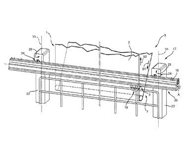
Fig. 1 indicates with the reference numeral 1 a
CA 02955283 2017-01-12
WO 2016/009354
PCT/IB2015/055324
monitoring system for monitoring the conditions of a band 2
circulating in a paper making machine 3 according to the
present invention.
Fig. I illustrates only a portion of the paper making
5 machine 3 comprising a band 2 and a return roller 4 around
which the band 2 circulates. The band 2 is circulated along
a first circulating direction Si upstream of the return
roller 4 and along a second circulating direction S2
downstream of the return roller 4.
In the non-limiting example described and illustrated
here, the portion of the paper making machine 3 illustrated
in Fig. I belongs to a press section and the portion of the
machine illustrated in Fig. I is located in a position
upstream of one of the presses of the pressing station. It
is understood that the system 1 according to the present
invention can also be installed in the drying sections
and/or in the forming sections of the paper making machine
3.
The system I comprises a detecting device 6 configured
to detect at least one parameter indicative of the
conditions of the band 2 and a moving assembly 7 configured
to move the detecting device 6 with respect to the band 2.
In the non-limiting example described and illustrated
here, the detecting device 6 is provided with a first
detector (not illustrated) configured to detect the
CA 02955283 2017-01-12
WO 2016/009354
PCT/IB2015/055324
6
humidity of the band 2, with a second detector (not
illustrated) configured to detect the permeability of the
band 2 and with a third detector configured to measure the
temperature of the band 2. In particular, the first
detector comprises at least one microwave sensor while the
second detector comprises at least one water dispensing
nozzle and one flow measuring device associated with the
nozzle. The detecting device 6 also comprises a control
unit (not illustrated), connected to the detectors to
process signals coming from them.
Preferably, the detecting device 6 is fed with water
by means of a water supply line 5 (visible in Figs. 5 and
6) and is provided with a battery power supply. In a
variant it is connected to the electricity supply network
by means of a cable.
In a further variant, not illustrated, the control
unit is arranged in a remote seat and communication between
the control unit and the detectors of the detecting device
6 takes place via cable or via wireless communication
systems.
It is understood that the detecting device 6 can
detect other parameters indicative of the conditions of the
band 2.
With reference to Fig. 4, the detecting device 6
comprises a case 8, inside which the first, the second and
CA 02955283 2017-01-12
WO 2016/009354
PCT/IB2015/055324
7
the third detector and the control unit are housed, a
handle 9 that can be gripped by an operator to manually
manoeuvre the detecting device 6, a perimeter frame 10
arranged around the case 8 and a binding element 11.
In the non-limiting example described and illustrated
here, the binding element 11 is defined by four binding
element blocks 12 fixed to the handle 9.
In particular, the binding element blocks 12 are
defined by a first jaw 13 and by a second jaw 14 clamped
around the handle 9. As will be seen in detail below, the
first jaw 13 of each binding element block 12 is provided
with a recess 15 (visible in Figs. 8 and 9).
With reference to Fig. 1, the moving assembly 7
comprises a supporting frame 17, a guide 18 supported by
the supporting frame 17, a carriage 19 movable along the
guide 16, and a moving device 20 configured to move the
carriage 19 along the guide 18.
The supporting frame 17 comprises two substantially
identical uprights 22, which are preferably arranged
parallel resting on the floor or on a suitable support base
at the sides of the band 2. Preferably the uprights 22
extend along two respective vertical axes V1 and V2.
The uprights 22 are preferably in the shape of a
parallelepiped and are respectively provided with a
coupling face 23 able to be coupled to the guide 18 by
CA 02955283 2017-01-12
WO 2016/009354
PCT/IB2015/055324
8
means of respective coupling means 24.
Preferably the coupling means 24 comprise screw
coupling systems, not visible in the accompanying figures.
In a variant not illustrated, the uprights are shaped,
for example, so as to define a housing seat able to house
and to support the guide 18.
The uprights 22 are preferably hollow to allow parts
of the system 1 to be housed therein, if necessary.
In a variant not illustrated, the supporting frame 17
is a portion of the main frame normally used also to
support other elements of the paper making machine 3.
The guide 18 extends along an axis A, orthogonal to
the axes V1 V2 of the uprights 22 and, therefore, extends
horizontally.
In other words, the guide 18 and the uprights 22
define a bridge structure.
In the non-limited example described and illustrated
here, the guide 18 is arranged in front of the band 2,
which substantially slides along an almost vertical
direction S2.
It is understood that the structure defined by the
uprights 22 and by the guide 18 can be shaped and arranged
so that the band 2 is located below the guide 18, or even
above the guide 18.
With reference to Fig. 5, the guide 18 comprises a
CA 02955283 2017-01-12
WO 2016/009354
PCT/IB2015/055324
9
guide element 26, which extends along the axis A and has a
substantially C-shaped cross section, along a plane
orthogonal to the axis A.
In particular, the guide element 26 comprises an upper
wall 27, a lower wall 28 parallel to the upper wall 27, a
lateral wall 29, coupled to the upper wall 27 and to the
lower wall 28 and orthogonal to both, and two lateral
appendices 30, which project orthogonally respectively from
the upper wall 27 and from the lower wall 28.
Preferably, the guide element 26 is produced in one
piece.
The guide element 26 thus shaped defines a
longitudinal seat 31 delimited by the upper wall 27, by the
lower wall 28, by the lateral wall 29 and by the two
lateral appendices 30.
The lateral wall 29 has an inner face 32, which faces
the seat 31 and an outer face 33, which is coupled to the
coupling faces 23 of the uprights 22. In particular, the
stretch of the outer face 33 comprised between the uprights
22 is coupled to a stiffening element 35, which is
configured to increase the rigidity of the guide element
26.
In particular, the stiffening element 35 extends
parallel to the longitudinal axis A and has a substantially
U-shaped cross section, along a plane orthogonal to the
CA 02955283 2017-01-12
WO 2016/009354
PCT/1B2015/055324
axis A.
The stiffening element 35 thus comprises a
longitudinal wall 36 and a plurality of longitudinal
appendices 37 that project from the longitudinal wall 36
5 and are coupled to the outer face 33 of the lateral wall
29. The coupling between the longitudinal appendices 37 and
the lateral wall 29 is preferably obtained by welding.
With reference to Figs. 2 and 3, the moving device 20
is a cable moving device comprising a moving member 40
10 arranged in the seat 31 in proximity of an upright 22, a
moving pulley 41, a return pulley 42 arranged in the seat
31 in proximity of the other upright 22 and a hauling cable
43.
The moving pulley 41 is rotatable about a rotation
axis 13 orthogonal to the axis A and is moved by the moving
member 40 connected to the moving pulley 41 via
transmission means (not illustrated). The moving pulley 41
comprises a substantially circular outer edge 45, which is
provided with a housing seat 44 configured to house the
hauling cable 43.
The moving member 40 is preferably a stepper motor and
is associated with a system for detecting the position of
the carriage 19 along the guide 18.
The return pulley 42 is rotatable about an axis C, has
a housing seat 46 configured to house the hauling cable 43
CA 02955283 2017-01-12
WO 2016/009354
PCT/1B2015/055324
11
and rotates idle drawn by the hauling cable 43.
The return pulley 42 is preferably coupled to a
tensioner 47, configured so as to adjust the position of
the return pulley 42 along the axis A. In particular, axial
adjustment takes place through screwing of the threaded pin
48.
The hauling cable 43 is preferably a steel cable. The
moving pulley 41 and the return pulley 42 are preferably
rubber coated.
With reference to Fig. 5 and Fig. 6, the carriage 19
comprises a main body 50, a supporting arm 51, a binding
element 52 able to be coupled to the binding element 11 of
the detecting device 6, shifting means 53 configured to
shift the binding element 52, and a grip member 54
configured to hook the carriage 19 to the hauling cable 43.
The carriage 19 also comprises a blocking device 55,
configured to selectively fix the binding element 11 to the
binding element 52.
In a variant not illustrated, the blocking device is
comprised in the detecting device and not in the carriage.
In the non-limiting example described and illustrated
here, the carriage 19 is also provided with an articulated
cable grommet 51a, coupled to one side of the supporting
arm 51 and configured to house the water supply line 5 of
the detecting device 6 and any other service cables.
CA 02955283 2017-01-12
WO 2016/009354
PCT/1B2015/055324
12
The main body 50 is housed in the seat 31 and slides
inside the seat 31 along the axis A due to the presence of
a plurality of first wheels 56 arranged preferably vertical
and rotatable resting on the upper wall 27 of the guide
element 26, a plurality of second wheels 57 arranged
preferably vertical and rotatable resting on the lower wall
28 of the guide element 26, a plurality of third wheels 58
arranged preferably horizontal and rotatable resting on the
lateral wall 29 of the guide element 26 and a plurality of
fourth wheels 59 arranged preferably horizontal and
rotatable resting on the appendices 30 of the guide element
26.
In the non-limiting example described and illustrated
here the main body 50 is provided with four first wheels
56, with four second wheels 57, with four third wheels 58
and with four fourth wheels 59. The presence of the wheels
56, 57, 58 and 59 stabilizes sliding of the carriage 19
along the guide 18.
The grip member 54 is preferably coupled to the face
of the main body 50 arranged in front of the inner face 32
of the lateral wall 29 of the guide element 26. Preferably,
the grip member 54 is associated with a tightening element
(not visible in the accompanying figures) configured to
tighten the hauling cable 43 if required.
Preferably, the main body is coupled to two protective
CA 02955283 2017-01-12
WO 2016/009354
PCT/1B2015/055324
13
covers (not visible in the accompanying figures) configured
to protect the seat 31 from processing residues,
contaminants, dust, etc. In this way, the area in which the
hauling cable 43 circulates is kept clean. Moreover, the
protective covers substantially close the seat 31, allowing
controlled pressurisation of the seat 31 in the case in
which this is considered necessary.
In detail, the protective covers are defined by thin
metal sheets having one end coupled to a rotating shaft
arranged at the ends of the guide 18 and one end coupled to
the carriage. The movement of the carriage causes unwinding
of one cover and winding of the other cover guaranteeing
protection of the seat 31 for the whole of its length.
The supporting arm 51 is coupled to the main body 50
and is shaped so as to define a central seat and two
lateral seats (not clearly visible in the accompanying
figures) able to house the shifting means 53 of the binding
element 52.
In particular, the shifting means 53 comprise an
actuator 60, preferably pneumatic, coupled to the binding
element 52 and housed inside the central seat of the
supporting arm, and two supporting pins 61 (only one of
which is visible in the accompanying figures), coupled to
the binding element 52, housed in the lateral seats of the
supporting arm 51 and guided slidingly by rollers of the
CA 02955283 2017-01-12
WO 2016/009354
PCT/1B2015/055324
14
supporting arm (not illustrated in the accompanying
figures).
In use, operation of the actuator 60 causes shifting
of the binding element 52 along the sliding direction D of
the supporting pins 61 (Fig. 6).
In the non-limiting example described and illustrated
here, the sliding direction D of the supporting pins 61 is
substantially orthogonal to the axis A.
In other words, operation of the actuator 60 causes
shifting of the binding element 52, and consequently of the
detecting device 6 coupled thereto, along a direction D
orthogonal to the axis A.
Shifting of binding element 52 causes, in use,
shifting of the detecting device 6 and is adjusted so that
the detecting device 6 is arranged at a distance from the
band 2 necessary to perform the detection operations. In
the non-limiting example described and illustrated here,
the detecting device 6 is arranged, in use, substantially
in contact with the band 2 as illustrated in Fig. 6.
With reference to Fig. 7, the binding element 52
comprises a plate 65, which is provided with a coupling
face 62 and with a supporting face 63 coupled, via
connecting means 64 (Figs. 5-6), to the actuator 60 and to
the supporting pins 61, and a plurality of protrusions 66,
which project from the coupling face 63 and are shaped so
CA 02955283 2017-01-12
WO 2016/009354
PCT/1B2015/055324
as to define a geometric coupling with the recesses 15 of
the binding element 11 of the detecting device 6 as also
illustrated in Figs. 8 and 9.
The connecting means 64 preferably comprise an angular
5 adjustment device (not clearly visible in the accompanying
figures), configured to adjust the angular position of the
plate 65 with respect to the sliding direction D of the
supporting pins 61.
The protrusions 66 are arranged on the coupling face
10 63 substantially at the vertices of a quadrilateral.
In a variant not illustrated, the binding element 52
is provided with recesses and the binding element 11 is
provided with protrusions configured so as to define a
geometric coupling with the recesses of the binding element
15 52.
With reference to Figs. 8 and 9, the binding element
11 and the binding element 52 are configured so as to
define a geometric coupling between each other. The
geometric coupling speeds up the operations of positioning
of the detecting device 6 on the carriage 19.
In the non-limiting example described and illustrated
here, the protrusions 66 are definite substantially by
cylindrical pins and the recesses 15 are defined by holes
with a substantially cylindrical cross section extending
along an axis E.
CA 02955283 2017-01-12
WO 2016/009354
PCT/1B2015/055324
16
The protrusions 66 are provided with a through hole
67. The recesses 15 are provided with a lateral opening 68,
preferably having a cylindrical cross section and extending
along a direction orthogonal to the axis E.
When geometrically coupled, the recesses 15 and the
protrusions 66 give rise to a blocking hole 70, defined by
alignment of the lateral opening 68 and of the through hole
67, able to cooperate with the blocking device 55.
With reference to Fig. 7, the blocking device 55
comprises a plurality of blocking elements 73 and an
actuator 74, configured to shift simultaneously the
blocking elements 73 between a unblocking position, wherein
the binding element 11 is not fixed to the binding element
52 and a blocking position wherein the binding element 11
is fixed to the binding element 52.
The blocking elements 73 are preferably four and are
configured to cooperate, in use, with a respective blocking
hole 70 defined by alignment of the lateral opening 68 and
of the through hole 67.
With reference to Figs. 8 and 9, each blocking element
73 comprises a cylinder 76, a piston 77 housed partially in
the cylinder 76 and moving in the cylinder 76, a stop ring
78 coupled to the piston 77, a first spring 79 and a second
spring 80.
The cylinder 76 is defined by a hollow main body
CA 02955283 2017-01-12
WO 2016/009354
PCT/1B2015/055324
17
extending along a longitudinal axis G, which defines a seat
81 inside which the piston 77 is partially housed. The
cylinder 76 is provided with two openings 82 produced on
the opposite base walls and substantially aligned along the
axis G and engaged, in use, by the piston 77.
Each cylinder 76 is supported by the plate 65 and is
arranged in proximity of a respective protrusion 66
substantially inside the quadrilateral defined by the
protrusions 66.
The first spring 79 is arranged around the piston 77
inside the seat 81 between the stop ring 78 and the base
wall of the cylinder 76 arranged in proximity of the
respective protrusion 66, while the second spring 80 is
arranged around the piston 77 inside the seat 81 between
the stop ring 78 and the base wall of the cylinder 76
distal with respect to the respective protrusion 66.
The piston 77 is provided with a first substantially
pointed end 84 and with a second end 85 coupled to the
actuator 74 by means of a transmission system 86 that will
be described in detail below.
In use, the cylinder 77 is operated by the actuator 74
to cooperate selectively with the respective blocking hole
70.
In particular, in the unblocking position illustrated
in Fig. 8, the first end 84 partially engages the blocking
CA 02955283 2017-01-12
WO 2016/009354
PCT/1B2015/055324
18
hole 70; in particular the first end 84 partially engages
only the lateral opening 68. In fact, in the unblocking
position the piston 77 is moved slightly forward inside the
blocking hole 70. This aspect does not prejudice the
geometric coupling between the recesses 15 and the
protrusions 66, as the end 84 produces a quick release
blocking.
In fact, in use when the block 12 is moved towards the
protrusion 66, the piston 77 is moved back by the block 12
due to the pointed shape of the first end 84. Instead, the
spring 80 pushes the end 84 until the end is aligned with
the blocking hole 80.
Similarly, detachment between the block 12 and the
protrusion 66 is not obstructed by the presence of the
first end 84 of the piston 77. In fact, during detachment,
the piston 77 is moved back by the block 12 due to the
combination of the pointed shape of the first end 84 and of
the suitable shape of the block 12.
This quick release coupling facilitates positioning of
the detecting device on the carriage 19 and ensures that
the subsequent blocking operations take place correctly and
without decelerations.
In the blocking position illustrated in Fig. 9, the
piston 77 completely engages the blocking hole 70, and in
particular engages both the lateral opening 68 and the
CA 02955283 2017-01-12
WO 2016/009354
PCT/1B2015/055324
19
through hole 67. In this way, detachment between the block
12 and the protrusion 66 is prevented.
Passage from the blocking position to the unblocking
position is also facilitated by the presence of the spring
79, which pushes the piston 77 out of the blocking hole 70
as soon as the pushing action of the actuator 74 ceases.
As already mentioned, the actuator 74 is configured to
operate simultaneously the pistons 77 of each blocking
element 73 due to a transmission system 86.
With reference to Fig. 7, the actuator 74 comprises a
cylinder 88 inside which there is housed a shaft 89
connected to a handle 90 and configured to rotate inside
the cylinder 88 by a maximum angle of 90 . The cylinder 88
is fixed to the transmission system 86.
As will be described in detail below, a pulling action
by an operator on the handle 90 causes operation of the
transmission system 86 to shift the blocking elements 73
from the unblocking position to the blocking position; the
consequent action of rotating the handle 90 instead causes
blocking of the blocking elements 73 in the blocking
position.
With reference to Fig. 10, the shaft 89 is provided
with a first cylindrical portion 92 and with a second
portion 93 having a quadrant cross section. A stop ring 94
is produced between the first cylindrical portion 92 and
CA 02955283 2017-01-12
WO 2016/009354
PCT/IB2015/055324
the second portion 93.
The cylinder 88 is hollow and is provided internally
with a semi-cylindrical fixed insert 95 able to define a
housing seat 96, also semi-cylindrical. In use, the shaft
5 89 is inserted inside the cylinder 88 so that the second
portion 93 is housed in the semi-cylindrical housing seat
96. In this way, the shaft 89 can rotate through a maximum
of 90 . Preferably, the shaft 89 can slide inside the
cylinder 88. Sliding of the shaft 89 inside the cylinder 88
10 is limited by the presence of a spring (not illustrated)
arranged around the first cylindrical portion 92 of the
shaft inside the cylinder 89. Moreover, the spring
facilitates the return movement of the shaft 88 inside the
cylinder 89 after the pulling action on the handle 90 by
15 the operator has been completed.
With reference to Figs. 11-14, the transmission system
86 comprises a main plate 100, fixed to which are the
cylinder 88 and the pistons 77 of two of the blocking
elements 73, a secondary plate 101, fixed to which are the
20 pistons 77 of the other two blocking elements 73, and a
lever 102.
The lever 102 is provided with a first end 104 coupled
to the main plate 100, with a second end 105 coupled to the
secondary plate 101 and with a central pivot 106 coupled to
a pin 107 that projects from the coupling face 62 of the
CA 02955283 2017-01-12
WO 2016/009354
PCT/1B2015/055324
21
plate 65.
The main plate 100 is provided with a slot 108 engaged
by a first pin 109 that projects from the first end 104 of
the lever 102 while the secondary plate 101 is provided
with a slot 110 engaged by a second pin 111 that projects
from the second end 105 of the lever 102.
Fig. 11 illustrates the unblocking position in which
the handle 90 is free and is not subjected to pulling by
the operator.
Fig. 12 illustrates the pulling movement on the handle
90 that causes shifting of the blocking elements 73 from
the unblocking position to the blocking position in which
the pistons 77 engage the blocking holes 70.
The simultaneous rotation of the handle through 90
allows the handle to be housed inside a groove 115 suitably
produced in the plate 65 (Fig. 13).
Release of the handle 90 causes the shaft 89 to return
inside the cylinder 88, blocking the handle 90 inside the
groove 115 (Fig. 14). In this way the blocking elements 73
are blocked in the blocking position.
In the non-limiting example described and illustrated here,
the binding element 52 is preferably provided with a plurality of
release elements 116 coupled to the plate 65 and configured to
facilitate detachment between the recesses 15 and the protrusions
66. More specifically, the release elements 116 comprise pins
CA 02955283 2017-01-12
WO 2016/009354
PCT/IB2015/055324
22
partially housed in cylinders coupled to the supporting face 63 of
the plate 65 and surrounded by springs.
Advantageously, the use of a cable moving device makes the
system according to the present invention simple and reliable. The
cable moving device is substantially self-cleaning and is therefore
capable of ensuring correct movement of the carriage even in the
presence of dust and processing residues.
Moreover, the use of a cable moving device makes the
monitoring system according to the present invention very compact,
particularly along the direction transversal to the circulating
direction of the band 2. This aspect is very important as the spaces
available, especially in the press section, are very limited.
Moreover, the use of protective covers drawn by the carriage
ensures that the seat 31 of the guide 18 inside which the carriage
19 slides is kept clean and, in conditions of extreme use, also
allows pressurisation of the seat 31.
Advantageously, the blocking device 55 is configured to block
the detecting device 6 to the carriage 19 with the operation of a
single actuator. Moreover, the carriage 19 and the detecting device
are shaped so as to initially establish a geometric coupling between
each other so as to facilitate subsequent blocking via the blocking
device 55.
Finally, it is evident that modifications and variants can be
made to the system and to the paper making machine described herein
without however departing from the scope of the appended claims.