Note: Descriptions are shown in the official language in which they were submitted.
CA 02955839 2017-01-19
WO 2016/049191 PCT/US2015/051731
ELECTRODEPOSITION MEDIUMS FOR FORMATION OF PROTECTIVE
COATINGS ELECTROCHEMICALLY DEPOSITED ON METAL SUBSTRATES
REFERENCE TO RELATED APPLICATIONS
[0001] The present application claims the priority of U.S. provisional
application Serial No.
62/054,223, entitled ELECTRODEPOSITION MEDIUMS FOR FORMATION OF
PROTECTIVE COATINGS ELECTROCHEMICALLY DEPOSITED ON METAL
SUBSTRATES, filed September 23, 2014, and hereby incorporates the same
application herein
by reference in its entirety.
TECHNICAL FIELD
[0002] The present disclosure generally relates to protective coatings formed
from
electrodeposition mediums being electrochemically deposited on metal
substrates and methods
thereof.
BACKGROUND
[0003] Untreated metal substrates can suffer from a variety of undesirable
attributes that limit
their usage in certain applications. For example, untreated metal substrates
can have soft, easily
damageable surfaces that are susceptible to oxidation and corrosion damage
from the
surrounding environment. Although it is known to use anodization processes to
provide a
protective layer, protective layers formed through an anodization process are
relatively thin, fail
to provide certain desirable attributes, and can be susceptible to chemical
corrosion, heat
cracking, and physical inflexibility. Consequently, it would be desirable to
provide an
electrochemical deposition process to provide metal substrates with effective
protective coating
layers that provide desirable benefits including, heat stability, physical
flexibility, and superior
heat transfer properties.
SUMMARY
[0004] In accordance with one example, an article includes an electrically
conductive metal
substrate and a protective coating. The protective coating is
electrochemically deposited from an
CA 02955839 2017-01-19
WO 2016/049191 PCT/US2015/051731
electrodeposition medium. The electrodeposition medium includes a silicon
alkoxide, one or
more quaternary ammonium compounds or quaternary phosphonium compounds, and
water.
[0005] In accordance with another example, a method of electrodepositing a
protective coating
on a conductive surface of a metal is provided. The method includes providing
an
electrodeposition medium, providing a metal substrate having a conductive
surface, providing a
cathode, contacting at least a portion of the conductive surface of the metal
substrate with the
electrodeposition medium, conducting current from the at least a portion of
the conductive
surface to the cathode, and forming a protective coating on the metal
substrate. The
electrodeposition medium includes a silicon alkoxide, one or more quaternary
ammonium
compounds or quaternary phosphonium compounds, and water.
[0006] In accordance with yet another example, an article includes an
electrically conductive
metal substrate and a protective coating. The protective coating is
electrochemically deposited
from an electrodeposition medium. The electrodeposition medium includes one or
more metal
carbonate salts, water, and optionally, an additive. The additive includes one
or more of a
phosphate compound, a fluoride compound, and a conjugate acid thereof.
BRIEF DESCRIPTION OF THE DRAWINGS
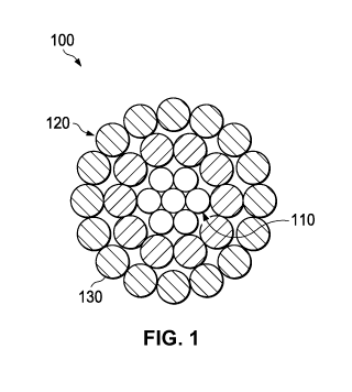
[0007] FIG. 1 depicts a cross-sectional view of a conductor in accordance with
certain
embodiments.
[0008] FIG. 2 depicts a cross-sectional view of a conductor in accordance with
certain
embodiments.
[0009] FIG. 3 depicts a cross-sectional view of a conductor in accordance with
certain
embodiments.
[0010] FIG. 4 depicts a cross-sectional view of a conductor in accordance with
certain
embodiments.
[0011] FIG. 5 depicts a schematic view of a test setup to evaluate reduction
of the operating
temperature of an electrically conductive wire formed with a protective
coating.
2
CA 02955839 2017-01-19
WO 2016/049191 PCT/US2015/051731
DETAILED DESCRIPTION
[0012] Electrochemical deposition processes can be useful in providing metal
substrates with a
protective coating. Such protective coatings deposited on metal substrates can
impart a number
of beneficial properties to the metal substrate including providing, superior
heat transfer
properties, physical flexibility, as well as resistance to damage and
corrosion from a surrounding
environment. The protective coating can be deposited onto the metal substrate
from the
electrodeposition medium. As can be appreciated, such electrodeposition from
the medium can
be different than anodization processes which form the protective coating from
the substrate
material. For example, in certain embodiments, about 5% or more of the
protective coating can
be from the electrodeposition medium. Additionally, the protective coating can
be formed of
chemical species different than the underlying metal substrate.
[0013] An electrochemical deposition process can involve several steps in
depositing a
protective coating to a metal substrate or other surface. For example, such
steps can include
providing an electrodeposition medium, exposing at least a portion of a metal
substrate to the
electrodeposition medium, and conducting current through the metal substrate
to
electrochemically deposit the protective layer on the metal substrate. As will
be appreciated, the
order of certain steps can vary or be combined with other steps. For example,
in certain
embodiments, an electrodeposition medium may be deposited around an existing
metal substrate,
e.g., an electrically conductive wire.
[0014] A variety of suitable electrodeposition mediums can be used in the
electrochemical
deposition process to form protective coatings that offer the benefits
described herein. In one
embodiment, an electrodeposition medium can include one or more metal
components (e.g., a
primary metal or metalloid compound), one or more quaternary ammonium
compounds, and
water. As can be appreciated, such electrodeposition mediums can be free of
organic solvent and
can be an aqueous solution. The water utilized can be any suitable water that
does not interfere
with the other components such as, for example, distilled water, deionized
water, or
demineralized water.
[0015] In certain embodiments, the metal components can be selected from a
metal oxide, a
metal hydroxide, an organometallic compound, a metal alkoxide compound, metal
complexes
3
CA 02955839 2017-01-19
WO 2016/049191 PCT/US2015/051731
with ketones or diketones, and combinations thereof Each metal component can
have an
element selected from zirconium (Zr), hafnium (Hf), yttrium (Y), zinc (Z),
silicon (Si), or any of
the lanthanide and actinide series metals. Illustrative examples of suitable
metal components can
include, zirconium isopropoxide, zirconium butoxide, zirconium ethoxide,
zirconium complexes
with suitable ligands, and combinations thereof.
[0016] In certain embodiments, one or more of the metal components can be a
silicon alkoxide
having the general formula Si(OR)4, where R is an alkyl group. Such metal
components are also
known as alkyl orthosilicates. Examples of suitable alkyl orthosilicates can
include tetraethyl
orthosilicate ("TEOS"), tetramethyl orthosilicate, tetrapropyl orthosilicate,
and tetrabutyl
orthosilicate. An electrodeposition medium including TEOS can be used to
produce a silicon
oxide protective coating on a metal substrate such as, for example, a silicon
dioxide protective
coating. In certain embodiments, the concentration of a silicon alkoxide in an
electrodeposition
medium can be from about 1 g/L to about 10 g/L.
[0017] In certain embodiments, one or more metal components can be inorganic
metal
complexes of zirconium including, for example, ammonium zirconium carbonate
("AZC"),
potassium zirconium carbonate, and sodium zirconium carbonate. In certain
embodiments, the
concentration of such inorganic metal complex in an electrodeposition medium
can be from
about 3 g/L to about 13 g/L.
[0018] In certain embodiments, one, or more, of the metal components can be
acidic metals or
acidic metalloid species including, for example, acidic metals such as
molybdic acid and boric
acid or acidic metalloid species such as vanadium pentoxide. The metal or
metalloid in such
examples can be selected from molybdenum, vanadium, boron, silicon,
phosphorus, tungsten,
tantalum, arsenic, germanium, tellurium, polonium, or niobium. In certain
embodiments, the
concentration of the acidic metal or acidic metalloid species in the
electrodeposition medium can
be from about 0.5 g/L to about 3.5 g/L.
[0019] In certain embodiments, the metal component can be aluminum iso-
propoxide and the
concentration of the aluminum iso-propoxide in the electrodeposition medium
can be from about
2 g/L to about 6 g/L.
4
CA 02955839 2017-01-19
WO 2016/049191 PCT/US2015/051731
[0020] In certain embodiments, one or more quaternary ammonium compounds or
quaternary
phosphonium compounds can be added to an electrodeposition medium including
the one or
more metal components. Suitable quaternary ammonium compounds can include
trimethyl
hydroxyethyl ammonium hydroxide ("choline"), tetra-butyl ammonium hydroxide,
benzyl
triethyl ammonium hydroxide, tetra ethyl ammonium hydroxide, tetra methyl
ammonium
hydroxide, and benzyl trimethyl ammonium hydroxide. Suitable quaternary
phosphonium
compounds in certain electrodeposition mediums can include tetra butyl
phosphonium
hydroxide, benzyl triethyl phosphonium hydroxide, tetra ethyl phosphonium
hydroxide, tetra
methyl phosphonium hydroxide, benzyl trimethyl phosphonium hydroxide, and
trimethyl
hydroxyethyl phosphonium hydroxide.
[0021] Suitable stoichiometric ratios between the one or more metal components
and the one or
more quaternary ammonium compounds can vary from a mol ratio of about 1:0.3 to
a mol ratio
of about 1:3. For example, an electrodeposition medium containing about 1 mol
of vanadium
pentoxide can include about 4 mol of trimethyl hydroxyethyl ammonium
hydroxide. In certain
embodiments, the one or more quaternary ammonium compounds have a
concentration in the
electrodeposition medium from about 0.5 g/L to about 10 g/L; and in certain
embodiments, from
about 1 g/L to about 5 g/L.
[0022] In other certain embodiments, additional electrodeposition mediums can
be utilized
including electrodeposition mediums that are essentially free of the one or
more metal
components and the one or more quaternary ammonium compounds or quaternary
phosphonium
compounds. For example, an electrodeposition medium can include one or more
metal salts and
can be essentially free of one or more quaternary ammonium compounds or
quaternary
phosphonium compounds. Suitable metal salts can include metal carbonate salts
or metal silicate
salts.
[0023] Metal carbonate salts can include salts of sodium, potassium, lithium,
rubidium, and
cesium with a carbonate functional group. Suitable metal carbonate salts can
include sodium
carbonate, sodium bi-carbonate, potassium carbonate, potassium bicarbonate,
lithium carbonate,
lithium bicarbonate, rubidium carbonate, rubidium bicarbonate, cesium
carbonate, and cesium
CA 02955839 2017-01-19
WO 2016/049191 PCT/US2015/051731
bicarbonate. In certain embodiments, a metal carbonate salt can be included in
an
electrodeposition medium at a concentration from about 0.1 g/L to about 10
g/L.
[0024] Metal silicate salts can include salts of water soluble monovalent
metal cations. Suitable
metal silicate salts can include lithium silicate, sodium silicate, sodium
metasilicate, potassium
silicate, rubidium silicate, and cesium silicate. In certain embodiments, a
metal silicate salt can
be included in an electrodeposition medium at a concentration of about 4 g/L.
[0025] Certain electrodeposition mediums, including, for example, aqueous-
based
electrodeposition mediums with a quaternary ammonium compound or a quaternary
phosphonium compound, can further include additional components. For example,
in certain
embodiments, a co-reactant modifier, or additive, can be included in an
electrodeposition
medium to improve the adhesion of the electrochemically deposited protective
coating to the
metal substrate and prevent chalking of the protective coating. Such a co-
reactant modifier, or
additive, can be a phosphate or fluoride chemical species, or a conjugate acid
thereof, such as
phosphoric acid, ammonium phosphate species, sodium phosphate species,
ammonium fluoride,
ammonium bi-fluoride, or combinations thereof In certain embodiments, a co-
reactant modifier
or additive can be included in an electrodeposition medium at a concentration
from about 1 g/L
to about 2 g/L.
[0026] Other components can also, or alternatively, be added to (or dispersed
in) an
electrodeposition medium including nanofillers/nanopowders and pigments.
Suitable
nanofillers/nanopowders that are added to an electrodeposition medium can
produce a hybrid
protective coating during the electrochemical deposition process. Such hybrid
coatings can
contain the nanoparticles in addition to the original components in the
electrochemically
deposited protective coating. These hybrid coatings can allow for the
formation of a protective
coating that has a rougher surface or a protective coating that has improved
durability or
thickness.
[0027] Suitable nanofillers/nanopowders that can be dispersed in an
electrodeposition medium
can include oxides, borides, nitrides, carbides, sulfides, silicides,
nanoclay, nanotalc,
nanocalcium carbonate, and other nano-sized fillers. Examples of such oxides
can include
aluminum oxide, zirconium oxide, cesium oxide, chromium oxide, magnesium
oxide, silicon
6
CA 02955839 2017-01-19
WO 2016/049191 PCT/US2015/051731
oxide, iron oxide, yttrium oxide, compound oxides, spinels, and combinations
thereof Likewise,
suitable examples of borides usable as a nanofiller/nanopowder can include
zirconium boride,
chromium boride, lanthanum boride, and combinations thereof Suitable examples
of nitrides can
include silicon nitride, aluminum nitride, boron nitride, and combinations
thereof. Examples of
carbides can include boron carbide, silicon carbide, chromium carbide,
zirconium carbide,
tantalum carbide, vanadium carbide, tungsten carbide, and combinations
thereof. Sulfide
nanofillers/nanopowders can include molybdenum sulfide, tungsten sulfide, zinc
sulfide, cobalt
sulfide and combinations thereof. Suitable silicides can include tungsten
silicide, and
molybdenum silicide. As will be appreciated, combinations of one or more
nanofillers/nanopowders can also be used in electrodeposition mediums.
[0028] In certain embodiments, suitable pigments useful for inclusion in an
electrodeposition
medium can include IR pigments, organic pigments, and inorganic pigments. As
will be
appreciated, pigments can vary in size and can, in certain embodiments, be a
nanofiller-sized
pigment. Examples of certain suitable pigments are disclosed in U.S. Patent
No. 7,174,079 which
is hereby incorporated by reference. IR pigments can improve the thermal
conductivity of a
protective coating by increasing reflection of incident infrared radiation.
[0029] Suitable electrodeposition mediums can generally have a pH greater than
7. For example,
an electrodeposition medium can have a pH of about 8 to about 14 in certain
embodiments, about
8 to about 11 in certain embodiments, or about 10 to about 11 in certain
embodiments.
[0030] During the electrochemical deposition process, an electrodeposition
medium is
substantially maintained as a liquid aqueous solution and placed in contact
with a least portion of
a metal substrate. The electrodeposition medium can be maintained in a
suitable container, such
as a bath or tank during this process at temperatures ranging from about 0 C
to about 90 C.
[0031] A metal substrate that is at least partially exposed and placed in
contact with an
electrodeposition medium can have a variety of different configurations,
shapes and/or desired
applications. For example, suitable metal substrates can have a variety of
shapes, such as flat,
curved, multi-contoured, wire-shaped, or other desired shapes that can
comprise all, or only a
portion, of a larger article's surface. As non-limiting, illustrative,
examples, the metal substrate
can be an electrical component such as an electronic winding, a circuit, a
transformer, a motor, a
7
CA 02955839 2017-01-19
WO 2016/049191 PCT/US2015/051731
rotor, a printed circuit board, an interconnection wire, or a wire for a
winding in a high vacuum
apparatus according to certain embodiments. Other illustrative examples of
such electrical
components can include metal substrates exposed to high temperatures such as
components or
wires of a turbine. The protective coating formed from the electrodeposition
processes can offer
electrical insulation, high temperature stability, and flexibility to such
metal substrates in certain
embodiments. As can be appreciated however, in other certain embodiments, the
protective
coating can alternatively be electrically semi-conductive or conductive.
[0032] According to certain embodiments, any metal substrate that is
electrically conductive can
be protected with a protective coating. Examples of suitable metal substrates
can include
substrates formed of one or more of aluminum, copper, steel, and magnesium.
[0033] Additionally, a coating can be applied to overhead transmission line
accessories. For
example, a substation can include a variety of accessories that can benefit
from the protectives
coatings as described herein including breakers and transformers such as
current coupling
transformers. Additional examples of transmission line accessories which can
also benefit from
such a protective coating can include deadends/termination products,
splices/joints, suspension
and support products, motion control/vibration products (sometimes referred to
as dampers),
guying products, wildlife protection and deterrent products, conductor and
compression fitting
repair parts, substation products, clamps, corona rings, connectors, busbars,
and any other
metallic objects employed on or near a transmission line.
[0034] In other certain embodiments, a metal substrate can be an aerospace
component such as
an engine component. The improved corrosion and wear resistance of the
protective coating can,
in certain such aerospace examples, replace other primers and pre-treatments
for aerospace
components and aluminized composites. As will be appreciated, the elimination
of primers or
pre-treatment can reduce manufacturing time and costs.
[0035] In certain embodiments, a metal substrate can include exterior
components for building
structures such as window frames, door frames, doors, sills, roofing tiles,
metal chimneys, and
any other metal component found in, or near, the building structures such as
fences, swimming
pool accessories or the like. Additionally, the metal substrate can be metal
components found on
decks, outdoor furniture, or lawn and gardening equipment. The protective
coating in such
8
CA 02955839 2017-01-19
WO 2016/049191 PCT/US2015/051731
examples can provide superior corrosion resistance and durability to the metal
substrate. As can
be appreciated, such corrosion resistance can be particularly beneficial for
real estate near certain
environments such as arid deserts, or saline oceans.
[0036] A metal substrate can also, in certain embodiments, be components of an
automotive
engine. As will be appreciated, automotive engines can operate through a wide
range of extreme
conditions including low-temperature short duration usage as well as extended
high-speed, high-
temperature usage. An electrochemically deposited protective coating can
provide automotive
engines and other automotive components with necessary wear resistance,
corrosion resistance,
and reduced friction to operate through such ranges of extreme conditions.
Reduction in friction
can also improve efficiency and the lifetime of such parts. Examples of other
suitable automotive
components can include pistons, intake manifolds, brake components, aluminum
structural
components, steel structural component, water pumps, cylinder heads, and
liners.
[0037] In other certain embodiments, a metal substrate can alternatively be a
component of
kitchen equipment. As non-limiting examples, the metal substrate can be a pot,
a pan, or can be a
component of kitchen equipment such as stand mixers, blenders, or food
processors. Such metal
substrates can benefit from the improved durability and heat protection of an
electrochemically
deposited protective coating.
[0038] As will be yet further appreciated, an electrochemically deposited
protective coating can
also be useful for metal substrates exposed to saline environments found near
saltwater or coastal
areas. As will be appreciated, the corrosion resistance of a protective layer
can improve the
durability and lifetime of such metal substrates. Examples of such metal
substrates can include
fasteners, aircraft engines, automotive parts, boats, and other marine
components commonly
found in, or near, saline environments. Examples of marine components can
include light metal
marine engine parts, outboards, and stern drives.
[0039] Additionally, a metal substrate can be a component of a heating,
ventilating, and air
conditioning ("HVAC") system. The protective coating in such systems can
provide components
with a longer lifetime and improved performance.
9
CA 02955839 2017-01-19
WO 2016/049191 PCT/US2015/051731
[0040] As can now be appreciated, the electrochemical deposition process can
be useful for a
variety of products and industries to provide a uniform, durable, and
attractive surface to metal
substrates.
[0041] Electrochemical deposition methods can provide a protective coating on
a conductive
metal substrate of an article in a batch process, a semi-batch process, or a
continuous process. In
certain embodiments, a batch process can be preferred to provide additional
flexibility to the
electrodeposition process. Generally, in a batch process, a conductive metal
substrate of an
article can be immersed in, or exposed to, an electrodeposition medium and
voltage to receive a
protective coating. However, many variations to such a batch process are
possible. For example,
a conductive metal substrate can be incrementally coated in certain batch
processes by exposing
only a small portion of the metal substrate to the electrodeposition medium,
forming a protective
coating on the small portion of the metal substrate, and then incrementally
exposing more of the
metal substrate to the electrodeposition medium. Such incremental batch
coating processes can
allow for reduced quantities of electrical current to be used or can allow for
articles of irregular
geometry to be coated. Incremental coating can also allow for smaller
electrodeposition baths to
be used. As can be further appreciated, other variations are also possible.
For example, one or
more portions of the conductive metal substrate can be protected from the
electrodeposition
medium with a water-proof coating, tape, or the like, to prevent
electrodeposition of the
protective coating in such covered portions. As can be appreciated, such steps
can allow an
article to have metal substrate portions unprotected by a protective coating.
Such unprotected
portions can be useful, for example, to allow for electrical connections or
mechanical
attachments to the article.
[0042] Alternatively, in certain embodiments, a metal substrate can be the
surface of a wire (e.g.,
an electrically conductive wire) or a multi-stranded wire. For example, each
individual strand of
a stranded wire can be protected by an electrochemically deposited protective
layer and then
stranded together to form a finished stranded conductor. Alternatively, only
certain strands, such
as the outer-most strands in such a stranded conductor, can be coated with an
electrochemically
deposited protective coating. In such stranded conductors, the outer-most
strands can be
protected with an electrochemically deposited protective coating and then
stranded together with
CA 02955839 2017-01-19
WO 2016/049191 PCT/US2015/051731
bare strands to form a stranded conductor. This configuration provides
stranded cables that offer
the benefits of an electrochemically deposited protective coating but at a
reduced cost.
[0043] In certain embodiments, an electrochemical deposition can also occur
subsequent to the
stranding of the conductors. In such embodiments, a previously stranded
conductor can be
immersed in, or exposed to, an electrochemical deposition medium and coated
with an
electrochemically deposited protective coating. As will be appreciated, such a
method can
provide a low-cost method of providing a protective coating to a multi-
stranded conductor.
[0044] Electrochemical deposition methods can provide a protective coating on
a conductive
surface of a wire through a batch process, a semi-continuous batch process, a
continuous process,
or a combination of such processes. In a continuous process, a strand, or a
multi-stranded
conductor are continually advanced through an electrochemical deposition
medium with voltage
to receive a protective coating. In contrast, in a batch process or semi-
continuous batch process,
bare individual strands or a multi-stranded conductor are wound on a drum and
then immersed in
an electrochemical deposition medium to electrochemically deposit a protective
coating.
[0045] In certain embodiments, a wire can be an overhead conductor. As can be
appreciated,
overhead conductors and cables can be formed in a variety of configurations
including aluminum
conductor steel reinforced ("ACSR") cables, aluminum conductor steel supported
("ACSS")
cables, aluminum conductor composite core ("ACCC") cables and all aluminum
alloy conductor
("AAAC") cables. ACSR cables are high-strength stranded conductors and include
outer
conductive strands, and supportive center strands. The outer conductive
strands can be formed
from high-purity aluminum alloys having a high conductivity and low weight.
The center
supportive strands can be steel and can have the strength required to support
the more ductile
outer conductive strands. ACSR cables can have an overall high tensile
strength. ACSS cables
are concentric-lay-stranded cables and include a central core of steel around
which is stranded
one, or more, layers of aluminum, or aluminum alloy, wires. ACCC cables, in
contrast, are
reinforced by a central core formed from one, or more, of carbon, glass fiber,
or polymer
materials. A composite core can offer a variety of advantages over an all-
aluminum or steel-
reinforced conventional cable as the composite core's combination of high
tensile strength and
low thermal sag enables longer spans. ACCC cables can enable new lines to be
built with fewer
11
CA 02955839 2017-01-19
WO 2016/049191 PCT/US2015/051731
supporting structures. AAAC cables are made with aluminum or aluminum alloy
wires. AAAC
cables can have a better corrosion resistance, due to the fact that they are
largely, or completely,
aluminum. ACSR, ACSS, ACCC, and AAAC cables can be used as overhead cables for
overhead distribution and transmission lines.
[0046] FIGS. 1, 2, 3, and 4 illustrate various bare overhead conductors
according to certain
embodiments. Each overhead conductor depicted in FIGS. 1-4 can include the
coating
composition. Additionally, FIGS. 1 and 3 can, in certain embodiments, be
formed as ACSR
cables through selection of steel for the core and aluminum for the conductive
wires. Likewise,
FIGS. 2 and 4 can, in certain embodiments, be formed as AAAC cables through
appropriate
selection of aluminum or aluminum alloy for the conductive wires.
[0047] As depicted in FIG. 1, certain bare overhead conductors 100 can
generally include a core
110 made of one or more wires, a plurality of round cross-sectional conductive
wires 120
locating around core 110, and a protective layer 130. The protective layer 130
can be
electrochemically deposited on conductive wires 120 or can be
electrochemically deposited on
only the exposed exterior portion of cable 100. The core 110 can be steel,
invar steel, carbon
fiber composite, or any other material that can provide strength to the
conductor. The conductive
wires 120 can be made of any suitable conductive material including copper, a
copper alloy,
aluminum, an aluminum alloy, including aluminum types 1350, 6000 series alloy
aluminum,
aluminum¨zirconium alloy, or any other conductive metal.
[0048] As depicted in FIG. 2, certain bare overhead conductors 200 can
generally include round
conductive wires 210 and a protective layer 220. The conductive wires 210 can
be made from
copper, a copper alloy, aluminum, an aluminum alloy, including aluminum types
1350, 6000
series alloy aluminum, an aluminum¨zirconium alloy, or any other conductive
metal. The
protective layer 220 can be electrochemically deposited on conductive wires
210 or can be
electrochemically deposited on only the exposed exterior portion of cable 200.
[0049] As seen in FIG 3, certain bare overhead conductors 300 can generally
include a core 310
of one or more wires, a plurality of trapezoidal-shaped conductive wires 320
around a core 310,
and the protective layer 330. The protective layer 330 can be
electrochemically deposited on
conductive wires 320 or can be electrochemically deposited on only the exposed
exterior portion
12
CA 02955839 2017-01-19
WO 2016/049191 PCT/US2015/051731
of cable 300. The core 310 can be steel, invar steel, carbon fiber composite,
or any other material
providing strength to the conductor. The conductive wires 320 can be copper, a
copper alloy,
aluminum, an aluminum alloy, including aluminum types 1350, 6000 series alloy
aluminum, an
aluminum¨zirconium alloy, or any other conductive metal.
[0050] As depicted in FIG. 4, certain bare overhead conductors 400 can
generally include
trapezoidal-shaped conductive wires 410 and a protective layer 420. The
conductive wires 410
can be formed from copper, a copper alloy, aluminum, an aluminum alloy,
including aluminum
types 1350, 6000 series alloy aluminum, an aluminum¨zirconium alloy, or any
other conductive
metal. The protective layer 420 can be electrochemically deposited on
conductive wires 410 or
can be electrochemically deposited on only the exposed exterior portion of
cable 400.
[0051] A protective coating can also, or alternatively, be utilized in
composite core conductor
designs. Composite core conductors are useful due to their lower sag at higher
operating
temperatures and their higher strength to weight ratio. A further reduction in
conductor
operating temperatures due to a protective coating can further lower the sag
of certain composite
core conductors and can lower the degradation of certain polymer resins in the
composite. Non-
limiting examples of composite cores can be found in U.S. Patent No.
7,015,395, U.S. Patent No.
7,438,971, U.S. Patent No. 7,752,754, U.S. Patent App. No. 2012/0186851, U.S.
Patent No.
8371028, U.S. Patent No. 7,683,262, and U.S. Patent App. No. 2012/0261158,
each of which are
incorporated herein by reference.
[0052] In certain embodiments, one or more of the wires in an overhead
conductor can
additionally be protected with a secondary coating in addition to the
electrochemically deposited
protective coating. Suitable examples of such secondary coatings can include
polytetrafluoroethylene, fluoroethylene vinyl ether copolymer, paint, or a
combination thereof
As can be appreciated, the secondary coating can be applied to individual
wires in the overhead
conductor or can be applied only to the exposed exterior portions of an
overhead conductor.
[0053] A metal substrate can generally be formed from a variety of suitable
metals including, for
example, aluminum, copper, steel, zinc, magnesium, or any alloy thereof In
certain
embodiments, the metal substrate can be galvanized. Non-limiting examples of
metal substrates
that can be galvanized include aluminum and steel metal substrates. In certain
embodiments, the
13
CA 02955839 2017-01-19
WO 2016/049191 PCT/US2015/051731
metal substrate can be formed of a different metal than the metal components
in the
electrodeposition medium. For example, if the metal substrate is formed from
aluminum or an
aluminum alloy, the protective coating can be silicon dioxide formed from an
electrodeposition
medium containing, for example, TEOS.
[0054] As will be appreciated, in certain embodiments, suitable metal
substrates can also be
formed on articles using techniques such as electroplating, galvanization, sol
gel deposition,
electroless depositions, and other know metal formation methods. Such
techniques can be used
independently, or in a multi-part process, to provide certain articles with
metal substrates
amenable to the application of an electrochemically deposited protective
coating.
[0055] In one embodiment, conducting a current can electrochemically deposit a
protective
coating on a metal substrate through a plasma electrolytic deposition process.
The metal
substrate can effectively act as an anode in an electrochemical cell in
conjunction with an
electrodeposition medium and a provided cathode. The cathode can be formed of
any suitable
metal and can, in certain embodiments, match the metal ion of the metal
components in the
electrodeposition medium. Alternatively, in certain embodiments, a titanium
cathode can be
used. However, the electrochemical deposition medium is not limited to plasma
electrolytic
deposition and can, in certain embodiments, be used in electrochemical
deposition processes that
utilize voltages too low for plasma formation.
[0056] The current can be direct current, pulsed direct current, or
alternating current. The current
density can suitably vary from about 1 amp/ft2 to about 30 amps/ft2 in certain
embodiments and
can suitably vary from about 5 amps/ft2 to about 15 amps/ft2 in certain
embodiments. The
average voltage potential can vary from about 0.1 volt to about 600 volts. In
certain
embodiments, the average voltage potential can vary from about 0.1 volt to
about 200 volts,
about 5 volts to about 100 volts in certain embodiments, and about 10 volts to
about 50 volts in
certain embodiments. In other certain embodiments, such as, for example,
plasma electrolytic
deposition embodiments, the average voltage potential can vary from about 250
volts to about
600 volts, from about 350 volts to about 600 volts in certain embodiments, and
from about 450
volts to about 550 volts in certain embodiments.
14
CA 02955839 2017-01-19
WO 2016/049191 PCT/US2015/051731
[0057] The current can be direct current or alternating current and can have
any suitable
waveform such as, for example, inverted sinewave, rectangular, triangular, and
square
waveforms. The frequency of such waveforms can vary from about 1 Hz to about
4,000 Hz. In
certain embodiments, the current can be pulsed.
[0058] The current can be applied for a limited period of time during the
electrochemical
deposition process. For example current can be conducted for about 5 seconds
to about 5 minutes
in certain embodiments, for about 15 seconds to about 3 minutes in certain
embodiments, and for
about 30 seconds to about 1 minute in certain embodiments. As can be
appreciated, such
durations can be substantially shorter than the durations necessary for an
anodization process.
[0059] As can be appreciated, an electrochemical deposition process can also
include additional
steps. For example, an electrochemical deposition process can include
pretreating a metal
substrate in order to clean and prepare the surface of the metal substrate
before exposing the
metal substrate to the electrodeposition medium. Suitable pretreatment steps
can include hot
water cleaning, ultrasonic cleaning, pressurized air cleaning, steam cleaning,
brush cleaning, heat
treatment, solvent wipe, plasma treatment, deglaring, desmutting,
sandblasting, acidic or basic
etching, passivation, and combinations thereof. Such processes can remove
dirt, dust, oil, and
oxidation or corrosion damage from the metal substrate before the
electrochemical deposition
process begins. Additionally, certain treatments, like passivation, can
increase the weight and
thickness of an electrochemically deposited protective coating layer. Such
treatments permit
additional flexibility in depositing a desired protective coating to a
particular metal substrate to
provide potential mechanical or electrical benefits to the final article.
[0060] Additionally, certain electrochemical deposition processes can also
include drying the
metal substrate subsequent to its contact with an electrodeposition medium.
Drying can occur
through a variety of methods such as through air drying or use of an oven
depending on various
circumstances including the size and configuration of the metal substrate. For
example, when
continuously electrochemically depositing a protective layer on a wire, it can
be advantageous to
dry the wire before the wire is rewound on a takeup spindle.
[0061] According to certain embodiments, an electrochemically deposited
protective coating can
have a number of desirable features including beneficial heat transfer
properties, thickness,
CA 02955839 2017-01-19
WO 2016/049191 PCT/US2015/051731
flexibility, corrosion resistance, and heat stability. As can be appreciated,
such beneficial
properties can improve various qualities of the underlying metal substrates
the protective coating
is deposited on. For example, an improved corrosion resistance can improve the
lifespan of a
wire conductor. Continuing, the protective coating can improve the current
carrying capacity and
ampacity of such wire by lowering the wire's operating temperature. As an
additional example
overhead conductors can have reduced ice and dust accumulation and improved
corona
resistance due to improved heat transfer, smoothness, and electrical
insulation properties of the
protective coating.
[0062] According to certain embodiments, an electrochemically deposited
protective coating can
have beneficial heat transfer properties that can help reduce the temperature
of the metal
substrate by dissipating heat faster than the untreated metal substrate alone.
For example, in
embodiments where the metal substrate is the surface of a wire, a conductor
(e.g., electrically
conductive wire) with an electrochemically deposited protective coating can
operate about 5 C
or more cooler than a comparative conductor without the electrochemically
deposited protective
coating when both wires are operated under similar operating conditions (e.g.,
at an operating
temperature measured at about 100 C or higher).
[0063] Electrochemically deposited protective coatings can have a desirable
thickness according
to certain embodiments. For example, the electrochemically deposited
protective coatings can
have a thickness from about 1 micron to about 100 microns in certain
embodiments, from about
microns to about 60 microns in certain embodiments, and from about 10 microns
to about 35
microns in certain embodiments. The variability in thickness at different
points of the metal
substrate can be minimal. For example, in certain embodiments, the thickness
of the
electrochemically deposited protective layer can vary by about 3 microns or
less, in certain
embodiments by 2 microns or less, and in certain embodiments by about 1 micron
or less.
[0064] In certain embodiments, articles having an electrochemically deposited
protective coating
can also demonstrate good flexibility and thermal stability. For example,
articles can show no
visible cracks when bent on a mandrel with a 0.5 inch diameter. In certain
embodiments, the
flexible coating can show no visible cracks when bent on mandrel diameters
ranging from 0.5
inch to 5 inches. Additionally, articles can also exhibit good resistance to
compressive forces.
16
CA 02955839 2017-01-19
WO 2016/049191 PCT/US2015/051731
For example, an electrical connector having a protective coating as described
herein can maintain
integrity (e.g., the protective coating can remain adhered to the connector
without cracking or
abrading) following the stresses caused by crimping the connector.
[0065] Additionally, in certain embodiments, an article having an
electrochemically deposited
protective coating can remain stable after various water submersion tests
including a water aging
test, and a salt water aging test.
[0066] According to certain embodiments, metal substrates coated with
electrochemically
deposited protective coatings can pass the ASTM B 117 salt spray test which
measures the
susceptibility of a metal to corrosion. A coated aluminum sample strip 13 cm
long, 1.2 cm wide,
and 0.1 cm tall from Example 2 in Table 1 passed about 1,100 hours without
corrosion or any
change in weight, or appearance.
[0067] According to certain embodiments, articles having an electrochemically
deposited
protective coating can also remain stable after exposure to acidic pH or basic
pH solutions.
[0068] An electrochemically deposited protective coating can be electrically
conductive, semi-
conductive or electrically insulating in certain embodiments. The conductance
of the protective
coating can vary depending on the quantity and thickness of each chemical
species
electrochemically deposited in the protective coating. As can be appreciated,
metal oxides such
as silicon dioxide are not electrically conductive and the quantity and
thickness of such an oxide
in the protective coating can influence electrical properties. It can
therefore be appreciated that
certain protective coatings, such as relatively thin protective coatings or
coatings that incorporate
certain additional fillers can be tailored for conductivity. As used herein,
"electrically non-
conductive" can mean a surface resistivity of about 104 ohm or greater. An
article having an
electrochemically deposited protective coating can, in certain embodiments,
have a surface
resistivity ranging from about 105 ohm to about 1012 ohm.
[0069] As can be appreciated, it can sometimes be desirable to remove a
protective coating from
a metal substrate. According to certain embodiments, a protective coating as
described herein
can be removed from a metal substrate through either mechanical forces or
chemical means. For
example, sufficient applied mechanical force can abrade the coating and
eventually cause
17
CA 02955839 2017-01-19
WO 2016/049191 PCT/US2015/051731
removal of the protective coating. As a specific example, a wire brush can be
used to remove a
protective coating from an electrical wire.
[0070] Alternatively, in certain embodiments, a solvent can be used to remove
a protective
coating as described herein. Generally, any suitable solvent that can dissolve
the protective
coating can be used to remove all, or a portion of, a protective coating.
Although many
commonly used solvents can be used, it can also be advantageous in certain
embodiments to use
solvents found in the electrodeposition mediums described herein. For example,
in certain
embodiments, quaternary ammonium compositions, such as choline, can be used to
dissolve a
protective coating.
Experimental
Test Methods
[0071] 1. Temperature reduction: Thermal data for test samples was measured by
applying a
current through a wire sample coated with a protective coating deposited from
inventive
electrochemical deposition process and an uncoated comparative wire sample.
The uncoated
wire sample was selected from a similar aluminum or aluminum alloy substrate,
but had no
protective layer. Each sample wire had a diameter of about 0.1075 inch and a
length of about 6.0
inches. Each sample was tested with the apparatus depicted in FIG. 5.
[0072] As depicted in FIG. 5, the test apparatus includes a 60Hz AC current
source, a true RMS
clamp-on current meter, a temperature datalog recording device, and a timer.
Testing was
conducted within a 68 inches wide x 33 inches deep windowed safety enclosure
to control air
movement around the sample. An exhaust hood was located 64 inches above the
test apparatus
for ventilation.
[0073] The sample to be tested was connected in series with the AC current
source through a
relay contact controlled by the timer. The timer was used to control the time
duration of the test.
The 60Hz AC current flowing through the sample was monitored by the true RMS
clamp-on
current meter. A thermocouple was used to measure the surface temperature of
the sample.
Using a spring clamp, the tip of the thermocouple was kept firmly in contact
with the center
18
CA 02955839 2017-01-19
WO 2016/049191 PCT/US2015/051731
surface of the sample. The thermocouple was monitored by the temperature
datalog recording
device to provide a continuous record of temperature.
[0074] Both uncoated and coated substrate samples were tested for temperature
rise on this
experimental set-up under identical conditions. The current was set at a
desired level and was
monitored during the test to ensure that a constant current was flowing
through the samples. The
timer was set at a desired value; and the temperature datalog recording device
was set to record
temperature at a recording interval of one reading per second.
[0075] For each test, the timer was activated concurrently with the current
source to start the test.
Once current was flowing through the sample, temperature immediately began
rising. This
surface temperature change was automatically recorded by the temperature
datalog recording
device. Once the testing period was completed, the timer automatically shut
down the current
source ending the test.
[0076] Once the uncoated sample was tested, it was removed from the set-up and
replaced by the
inventive sample with a protective coating. The inventive sample was tested in
the same manner
as the comparative uncoated sample.
[0077] The temperature test data was then accessed from the temperature
datalog recording
device and analyzed using a general purpose computer.
[0078] 2. Flexibility Bend Test: The flexibility of the coating was tested
both before and after
heat aging using a Mandrel Bend test. In the Mandrel Bend Test, samples are
bent on cylindrical
mandrels of decreasing size and observed for any visible cracks in the coating
at each of the
mandrel sizes. The presence of visible cracks indicates failure of the sample.
As can be
appreciated, a decrease in the diameter of the mandrel increases the
difficulty of the test.
Samples were also heat aged to test the thermal stability of the protective
coating. Samples were
heat aged by placed the samples in an air circulation oven at a temperature of
2500C for 7 days
and then placed at room temperature for a period of 24 hrs. Samples are
considered to have
passed the Mandrel Bend Test if they do not have visible cracks when bent on
mandrels having
diameters as small as 0.5 inch both before and after heat aging. Wire samples
having a diameter
of 0.1075 inch and a length of 6.0 inches were used for the Mandrel Bend Test.
While the
19
CA 02955839 2017-01-19
WO 2016/049191 PCT/US2015/051731
Mandrel Bend Test is performed on a wire sample, the Mandrel Bend Test may be
available for
other metal substrates, or other flexibility bend tests can be developed or
used in conjunction
with other metal substrates.
[0079] 3. Water aging: Samples were weighed on a balance and then water aged
in water at 90
C for 7 days. The samples were subsequently weighed again on a balance to
determine the
weight change. Wire samples having a diameter of 0.1075 inch and a length of
6.0 inches were
used for water aging.
[0080] 4. Salt solution aging: Samples were weighed on a balance and then
submerged in a 3%
sodium chloride aqueous solution for 7 days. The samples were subsequently
weighed again on a
balance to determine the weight change. Wire samples having a diameter of
0.1075 inch and a
length of 6.0 inches were used for water aging.
[0081] 5. Acidic or basic pH aging: Acidic pH solutions were prepared from
dilution of
concentrated sulfuric acid in water to form a solution with a pH of about 3 to
about 4. Similarly,
basic solutions were prepared from dilution of sodium hydroxide in water to
form a solution with
a pH of about 10 to about 11. Wire samples having a diameter of 0.1075 inch
and a length of 6.0
inches were used for Acidic or Basic pH aging.
[0082] 6. Salt Spray test: The Salt Spray test was conducted in accordance
with ASTM B 117. In
the ASTM B 117 test, a sharp blade is used to cut a cross mark through the
protective coating to
expose the bare metal surface. The sample is then sprayed with a salt bath
spray in accordance
with ASTM B 117 and then observed to note any corrosion at the cross mark,
change in color or
smoothness of the coating, or any weight change in the sample. Test samples
were 13 cm long,
1.2 cm wide, and 0.1 cm tall.
[0083] Electrochemical deposited protective coatings deposited on metal
substrates were
evaluated using a standardized test procedure beginning with the preparation
of an
electrodeposition medium and the preparation of test samples. Each
electrodeposition medium
was prepared with the components disclosed in Table 1 using laboratory-grade
reagents.
Components were added sequentially to a 100 mL solution of demineralized water
with each
component added in a calculated stoichiometric quantity to the first added
component. If
CA 02955839 2017-01-19
WO 2016/049191 PCT/US2015/051731
multiple components were added, the metal component (e.g., primary metal or
metalloid
compound) was added last. Each electrodeposition medium was continually
stirred until the
metal component was completely dissolved. Additional demineralized water was
then added to
form a 1 liter solution for the electrodeposition medium.
[0084] Test samples were prepared using aluminum test strips or wire as noted
in the Test
Methods section. Test strips were formed from International Alloy Designation
System
aluminum alloy 1350. Each sample was surface treated by degreasing with
acetone, etching in a
solution of sodium or potassium hydroxide (50 g/L for 1 minute), rinsing in
demineralized water,
desmutting in 20% nitric acid for 1 minute, re-rinsing in demineralized water,
and then wiped
with a clean cloth to dry. To record weight gain, each test sample was weighed
on a balance
before the electrochemical deposition process.
[0085] Unless otherwise noted, test samples were electrochemically coated with
a protective
coating by submerging the test samples in an electrodeposition medium and
connecting the test
samples as an anode. Titanium cathodes were also submerged in the aqueous
solution. Voltage
between the two electrodes was raised steadily to about 400 volts and up to
about 550 volts and
maintained for about a minute. Plasma was observed during the electrochemical
deposition
process. After the electrochemical deposition process was completed, the test
samples were
removed, washed with demineralized water, and then dried and weighed.
21
CA 02955839 2017-01-19
WO 2016/049191 PCT/US2015/051731
TABLE 1
Ex# Electrodeposition Weights Mole Ratio Voltage Duration %
Coating
medium (g/L of of (V) (min)
Increasing thickness
water) of components
in weight (microns)
components
1 TEOS + Choline 5.5:13 1:4 500 1 <0.5
12.7
2 Sodium Carbonate 2 NA 530 1 1.25
35
Sodium Carbonate +
3 2:1.5 1:0.8 530 1 2.81 45.2
Phosphoric acid
4 AZC+ Choline 8.5:3.7 1: 1.1 500 1 2.73
35
AZC+ Choline +
8.5: 3.7: 1.5 1: 1.1: 0.5 500 1 1.23 13
Phosphoric acid
6 Sodium metasilicate 4 NA 530 1 --
14
Molybdic acid +
71.6: 2.4 1:2 500 1 0.07
11.5
Choline
Molybdic acid +
8 Choline 1.6: 2.4: 1.5 1:2:0.76 500 1 0.61
30.5
+Phosphoric acid
Vanadium
9 1.8:4.8 1:4 500 1 0.37 19.1
pentoxide + Choline
Aluminium iso-
4: 7.1 1:3 500 1 -- --
propoxide + Choline
[0086] Table 1 depicts the chemistries of each of the electrodeposition
mediums (excluding
water) used to prepare test samples including the mole ratio and weights
between each of the
respective components. Table 1 also depicts the voltages used to
electrochemically deposit a
protective coating on each respective test samples, the duration of the
electrochemical deposition
process in coating the respective test samples. Table 1 further depicts the
results of such
electrochemical deposition methods and displays the weight gain and coating
thickness
associated with each electrodeposition chemistry.
22
CA 02955839 2017-01-19
WO 2016/049191 PCT/US2015/051731
TABLE 2
Ex Operating Bend Bend % % % % Surface
# Temperature test test Change Change Change Change resistivity
Reduction (initial) (Aged in
in in weight in weight (ohm)
(%) 7 day weight weight (after
(after
at 250 (after (after aging in aging in
C) water 3% salt (3-4) pH (10-11)
aging at aging 7 for 7 pH for 7
90 C days) days) days)
for 7
days)
1 22.1 Pass Pass -0.03 0.01 0.00 -0.12 108
2 14.8 Pass Pass 0.97 0.26 0.20 0.43
1010
3 -- Pass Pass -- -- -- --
1010
4 15.9 Pass Pass 0.95 0.24 0.22 0.17 109
15.9 Pass Pass -0.08 0.04 0.02 -0.07 109
6 4.7 Pass Pass 0.06 0.03 -0.39 -0.05 108
7 7.7 Pass Pass 0.04 0.02 0.00 -0.09 109
8 -- Pass Pass -- -- -- --
1010
9 -- Pass Pass -- -- -- -- 108
-- Pass Pass -- -- -- -- 108
[0087] Table 2 depicts the results of testing performed on the examples formed
from the
electrodeposition medium and methods described in Table 1. The operating
temperature
reduction, Mandrel Bend Test, water aging, and surface resistivity for each
example sample are
also reported in Table 2.
23
CA 02955839 2017-01-19
WO 2016/049191 PCT/US2015/051731
TABLE 3
Comparative Comparative Example
Example 1 2
Substrate Aluminum 1350 Aluminum 1350
Coating Sodium silicate + Zinc Aluminum oxide
Oxide
Application of Coating Brushed Anodized
Bend test (Initial) Mandrel Cracks observed on a Cracks observed on a
Size mandrel with a mandrel with a diameter
diameter of 4 inches of 8 inches
Bend test (Aged 7 day at Cracks observed on a Cracks observed on a
250 C) Mandrel Size mandrel with a mandrel with a diameter
diameter of 4 inches of 8 inches
[0088] Table 3 depicts the results of the Mandrel Bend Test of Comparative
Examples 1 to 2.
The comparative examples include protective coatings applied by a brushing as
well as
anodization to 12.0 inches (L) by 0.50 inch (W) by 0.028 inch (T) aluminum
1350 grade
samples. The thickness of the coating layer in Comparative Example 1 was about
8-10 microns
and was about 20 microns in Comparative 2. The comparative examples failed the
Mandrel Bend
Test as the protective coatings cracked on the mandrels. In contrast,
inventive examples 1 to 10
all passed the Mandrel Bend Test by not cracking on mandrels having a diameter
as small as 0.5
inch.
[0089] Table 4 depicts the elemental composition of protective coatings formed
of Example 1
(TEOS and choline) and Example 2 (sodium carbonate) described in Tables 1 and
2. The
elemental composition of each example was determined by forming samples of the
protective
coating and examining the samples on a scanning electron microscope (TopCon SM
300 electron
microscope using a tungsten filament providing 50x-100,000x magnification).
After identifying
the protective coating, an attached silicon drift energy-dispersive x-ray
spectroscopy detector
(IXRF Iridium Ultra) was used to measure the elemental composition.
24
CA 02955839 2017-01-19
WO 2016/049191 PCT/US2015/051731
TABLE 4
Element Example 1 Example 2
Silicon 11.4% 2.9%
Carbon 18.4% 14.8%
Oxygen 18.3% 20.5%
Fluorine 0.0% 3.1%
Sodium 1.5% 0.7%
Aluminum 45.2 % 46.7 %
Phosphorus 2.6 % 8.3 %
Chlorine 0.2 % 0.1 %
Potassium 0.4 % 0.2 %
Titanium 1.8% 2.7%
[0090] The dimensions and values disclosed herein are not to be understood as
being strictly
limited to the exact numerical values recited. Instead, unless otherwise
specified, each such
dimension is intended to mean both the recited value and a functionally
equivalent range
surrounding that value.
[0091] It should be understood that every maximum numerical limitation given
throughout this
specification includes every lower numerical limitation, as if such lower
numerical limitations
were expressly written herein. Every minimum numerical limitation given
throughout this
specification will include every higher numerical limitation, as if such
higher numerical
limitations were expressly written herein. Every numerical range given
throughout this
specification will include every narrower numerical range that falls within
such broader
numerical range, as if such narrower numerical ranges were all expressly
written herein.
[0092] Every document cited herein, including any cross-referenced or related
patent or
application, is hereby incorporated herein by reference in its entirety unless
expressly excluded
or otherwise limited. The citation of any document is not an admission that it
is prior art with
respect to any invention disclosed or claimed herein or that it alone, or in
any combination with
CA 02955839 2017-01-19
WO 2016/049191 PCT/US2015/051731
any other reference or references, teaches, suggests, or discloses any such
invention. Further, to
the extent that any meaning or definition of a term in this document conflicts
with any meaning
or definition of the same term in a document incorporated by reference, the
meaning or definition
assigned to that term in the document shall govern.
[0093] The foregoing description of embodiments and examples has been
presented for purposes
of description. It is not intended to be exhaustive or limiting to the forms
described. Numerous
modifications are possible in light of the above teachings. Some of those
modifications have
been discussed and others will be understood by those skilled in the art. The
embodiments were
chosen and described for illustration of various embodiments. The scope is, of
course, not
limited to the examples or embodiments set forth herein, but can be employed
in any number of
applications and equivalent articles by those of ordinary skill in the art.
Rather it is hereby
intended the scope be defined by the claims appended hereto.
26