Note: Descriptions are shown in the official language in which they were submitted.
CA 02956100 2017-01-24
A SWITCHING DEVICE FOR LV ELECTRIC INSTALLATIONS
DESCRIPTION
The present invention relates to the field of switching devices (such as
circuit breakers,
contactors, disconnectors and the like) for low voltage electric
installations.
For the purposes of the present application, the term "low voltage" (LV)
relates to operating
voltages lower than 1 kV AC and 1.5 kV DC.
As is known, switching devices for LV electric installations comprise one or
more electric poles
intended to be electrically connected to the conductors of a LV electric line.
Each electric pole comprises one or more mobile contacts and fixed contacts
that can be
mutually coupled/uncoupled.
Typically, a LV switching device comprises mechanical control means adapted to
provide an
actuation force to move the mobile contacts from a coupling position to an
uncoupling position
with the corresponding fixed contacts, or vice-versa.
In many LV switching devices (as in the one described in the patent
application nr.
PCT/EP2009/067995) the mentioned mechanical control means comprise an outer
handle,
which is intended to be operated by a user or an actuator (e.g. a MOE - Motor
Operated
Actuator) to perform an opening or a closing manoeuvre of the switching
device.
In traditional switching devices, an opening manoeuvre generally requires a
relatively long time
(even up to some seconds) to be completed.
This is a critical aspect for the operating life of the switching device as
such a long time to
separate the electric contacts favours the occurrence of huge and prolonged
electric arc
phenomena with consequent wear and shortening of the useful operating life of
the electric
contacts themselves.
As it is easy to understand, all these drawbacks entail relatively high
operative costs for the
switching device, as maintenance interventions on the electric contacts are
frequently required.
In the field of LV switching devices for LV installations, it is thus quite
felt the need for new
solutions to reduce the time required to separate the electric contacts during
an opening
manoeuvre.
On the other hand, the experience has shown how this task is quite problematic
to carry out as
the mentioned mechanical control means have generally a quite complex
structure difficult to
put together to ensure all the functionalities requested for the operating
life of the switching
device
It is an object of the present invention to provide a switching device for LV
electric installations,
1
CA 02956100 2017-01-24
which allows overcoming the above-mentioned problems.
More in particular, it is an object of the present invention to provide a
switching device, in
which a short time is required to separate the electric contacts during an
opening manoeuvre.
Another object of the present invention is to provide a switching device
having a simple and
compact structure that is easy to manufacture and assembly at industrial
level.
Another object of the present invention is to provide a switching device that
can be realized, at
industrial level, at competitive costs in comparison to currently available
switching devices of
the same type.
In order to achieve these aim and objects, the present invention provides a
switching device,
according to the following claim 1 and related dependent claims.
In a general definition, the switching device, according to the invention,
comprises:
- one or more electric poles, each of which comprises one or more
mobile contacts and one or
more fixed contacts adapted to be coupled or uncoupled;
- a mobile contact assembly comprising said mobile contacts and reversibly
movable between
a first contact position, at which said movable contacts and said fixed
contacts are coupled,
and second contact position, at which said movable contacts and said fixed
contacts are
uncoupled;
- a mechanical control assembly for operating said mobile contact assembly.
Such a mechanical control assembly comprises a control mechanism for
reversibly moving said
mobile contact assembly between said first and second contact positions and a
trip mechanism
operatively coupled with said control mechanism, which comprises a trip shaft
reversibly
movable between a first trip position and a second trip position.
Said control mechanism is adapted to move said mobile contact assembly from
said first contact
position to said second contact position in response to a movement of said
trip shaft from said
first trip position to said second trip position.
Said mechanical control assembly comprises a handle mechanism operatively
coupled with said
control mechanism, which comprises a handle adapted to be reversibly moved by
a user or an
outer actuator between a first handle position and a second handle position in
order to carry out
a closing or an opening manoeuvre of the switching device.
Said control mechanism is adapted to move said mobile contact assembly from
said first contact
position to said second contact position in response to a movement of said
handle from said first
handle position to said second handle position (opening manoeuvre) and to move
said mobile
contact assembly from said second contact position to said first contact
position in response to
2
CA 02956100 2017-01-24
,
. .
a movement of said handle from said second handle position to said first
handle position (closing
manoeuvre).
According to the invention, said mechanical control assembly comprises an
activation
mechanism adapted to operatively couple said handle mechanism with said trip
shaft in order
to actuate said trip shaft during an opening manoeuvre of the switching
device, when said handle
is operated by a user or an outer actuator.
In particular, said activation mechanism is adapted to operatively couple said
handle mechanism
with said trip shaft in order to move said trip shaft from said first trip
position to said second
trip position during an opening manoeuvre of the switching device, namely
during a movement
of said handle from said first handle position towards said second handle
position upon an
actuation by a user or an outer actuator.
Preferably, said activation mechanism is adapted to be actuated by said handle
mechanism and
to transmit a force to said trip shaft to move said trip shaft from said first
trip position to said
second trip position during an opening manoeuvre of the switching device, in
particular during
a movement of said handle from said first handle position towards said second
handle position
upon the actuation by a user or an outer actuator.
Preferably, said activation mechanism comprises an activation lever hinged to
a support element
and movable with respect to said support element.
Preferably, said activation lever is translationally and rotationally movable
with respect to said
support element.
Preferably, the activation lever is adapted to be actuated by said handle
mechanism when said
handle moves from said first handle position towards said second handle
position.
Preferably, the activation lever is adapted to move translationally with
respect to said support
element from a first lever position to a second lever position and transmit a
force to said trip
shaft to move said trip shaft from said first trip position to said second
trip position in response
to an actuation by said handle mechanism during an opening manoeuvre of the
switching device,
in particular during a movement of said handle from said first handle position
towards said
second handle position upon the actuation by a user or an outer actuator.
According to some embodiments of the invention, said support element is fixed
with respect to
an outer casing of said switching device.
In this cases, said activation lever is adapted to be actuated by the trip
shaft to return in the first
lever position during a movement of said trip shaft from said second trip
position to said first
trip position.
3
CA 02956100 2017-01-24
Furthermore, said activation lever is adapted to be actuated by the handle
mechanism and
rotationally move with respect to said support element during a closing
manoeuvre of the
switching device, in particular during a movement of said handle from said
second handle
position to said first handle position upon the actuation by a user or an
outer actuator.
According to other embodiments of the invention, said support element is
movable with respect
to an outer casing of said switching device.
In these cases, said activation lever is adapted to be actuated by said
support element to return
in said first lever position during a closing manoeuvre of the switching
device, in particular
during a movement of said handle from said second handle position to said
first handle position
upon the actuation by a user or an outer actuator.
Furthermore, said activation lever is adapted to remain uncoupled from said
handle mechanism
during a closing manoeuvre of the switching device, in particular during a
movement of said
handle from said second handle position to said first handle position upon the
actuation by a
user or an outer actuator.
Further characteristics and advantages of the present invention will emerge
from the description
of preferred, but not exclusive, embodiments, non-limiting examples of which
are provided in
the attached drawings, in which:
- Figures 1-7 show a schematic view of an embodiment of the switching
device, according to
the invention;
- Figures 8-15 show a schematic view of a further embodiment of the switching
device,
according to the invention.
Referring to the cited figures, the present invention relates to a switching
device 1 suitable to
be installed in a LV electric switchgear panel or, more generally, in a LV
electric power
distribution grid.
As an example, the switching device 1 may be an automatic MCCB (Molded Case
Circuit
Breaker) for LV applications.
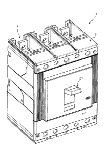
Preferably, the switching device 1 comprises an outer casing 2 defining an
internal volume 10
of the switching device (figures 1-2, 8-9).
The outer casing 2 may be arranged, in many respects, according to solutions
known to the
skilled person and it is not described with a high degree of detail for the
sake of brevity.
In general, the outer casing 2 comprises a plurality of shaped portions having
protrusions and
cavities at least partially geometrically conjugated or complementary to
define the internal
volume 10 of the switching device and ensure a suitable mutual mechanical
coupling.
4
CA 02956100 2017-01-24
The outer casing 2 may be made of an electrically insulating material (e.g.
thermosetting resins).
However, in some applications (e.g. when the switching device 1 is an air
circuit breaker), the
outer casing 2, or some portions thereof, can be made of an electrically
conductive material. Of
course, in these cases, suitable insulating elements need to be arranged
between the electrically
powered members of the switching device and the outer casing 2.
The switching device 1 comprises one or more electric poles 3.
Each electric pole 3 comprises one or more mobile contacts 31 and one or more
fixed contacts
32 adapted to be coupled or uncoupled.
When the electric contacts 31, 32 are coupled, the switching device 1 is in a
closing state
whereas, when the electric contacts 31, 32 are uncoupled, the switching device
1 is in an
opening state or a tripping state.
In the embodiments shown in the cited figures, the switching device 1 is of
the three-pole type
and comprises three electric poles 3, each comprising a plurality of fixed
contacts 32 and a
plurality of mobile contacts 31 that can be coupled or uncoupled.
Other solutions are however possible depending on the specific application of
the switching
device 1.
The electric poles 3 and the electric contacts 31, 32 may be arranged, in many
respects,
according to solutions known to the skilled person and it is not described in
a high degree of
detail for the sake of brevity.
In some embodiments of the switching device (as shown in the figure 3), each
mobile contact
31 may be adapted to be coupled/uncoupled at its opposite ends with/from a
corresponding pair
of fixed contacts 32 (double breaking configuration) in turn electrically
connected to an electric
power distribution line.
According to other embodiments (not shown), each mobile contact may 31 may
have an end
intended to be coupled/uncoupled with/from a corresponding fixed contact and
an opposite end
electrically connected to an electric power distribution line.
Further solutions are possible depending on the specific application of the
switching device 1.
The switching device 1 comprises a mobile contact assembly 4 including the
mobile contacts
31 and at least partially accommodated in the internal volume 10 of the
switching device.
Also the mobile contact assembly 4 may be arranged, in many respects,
according to solutions
known to the skilled person and it is not described with a high degree of
detail for the sake of
brevity.
In general, the mobile contact assembly 4 comprises a contact shaft 41 adapted
to rotate about
CA 02956100 2017-01-24
a first rotation axis 400 during a switching operation of the switching
device.
Preferably, the contact shaft 41 has an elongated shaped body (e.g. of
cylindrical type)
extending longitudinally along its rotation axis 400 and at least partially
made of an insulating
material (e.g. a thermosetting resin).
Preferably, the contact shaft 41 comprises one or more contact seats (not
shown) adapted to
accommodate, at least partially, one or more mobile contacts 31 in such a way
these latter
protrude from the main body thereof, perpendicularly with respect to the
longitudinal axis 400.
In this way, the mobile contacts 31 and the contact shaft 4 can solidly rotate
about the rotation
axis 400 during a switching operation of the switching device.
Other solutions are however possible depending on the specific application of
the switching
device 1.
The mobile contact assembly 4 is reversibly movable between a first contact
position Cl, at
which the movable contacts 31 and the fixed contacts 32 are coupled, and a
second contact
position C2, at which the movable contacts 31 and the fixed contacts 32 are
uncoupled.
In the cited figures, the mobile contact assembly 4 is shown only in the
embodiment of figures
1-7 for the sake of brevity. However, the mentioned mobile contact assembly is
an essential
part also of the embodiment of figures 8-16.
The switching device 1 comprises a mechanical control assembly 5 for operating
the mobile
contact assembly 4.
The mechanically control assembly 5 is at least partially accommodated in the
internal volume
of the switching device 1.
The mechanical control assembly 5 comprises a control mechanism 6 for
reversibly moving the
mobile contact assembly 4 between the first and second contact positions Cl,
C2.
Also the control mechanism 6 may be arranged, in many respects, according to
solutions known
to the skilled person and it is not described with a high degree of detail for
the sake of brevity.
In general, the control mechanism 6 is adapted to take different operative
configurations,
namely a closing, a tripping or an opening configuration, which relate to
corresponding
manoeuvres of the switching device, namely a closing, a tripping or an opening
manoeuvre,
respectively.
When the control mechanism 6 takes a closing configuration, the mobile contact
assembly 4
moves in the first contact position Cl and the switching device takes a
closing state (closing
manoeuvre of the switching device).
When the control mechanism takes a tripping configuration or an opening
configuration, the
6
CA 02956100 2017-01-24
, .
,
mobile contact assembly 4 moves in the second contact position C2 and the
switching device
takes a tripping state or an opening state, respectively (tripping or opening
manoeuvre of the
switching device).
Preferably, the control mechanism 6 comprises movable control members 61, 611
(e.g. shafts,
rods, springs, levers or the like), which are operatively arranged in such a
way to be capable to
provide a force to move the contact assembly 4.
Preferably, the control mechanism 6 comprises supporting frame members 62, 621
(e.g. shaped
frame plates or the like), which are fixed to the outer casing 2 (e.g. by
means of screws, bolts
or tie-rods or the like) to provide support to the movable members 61, 611.
The mechanical control assembly 5 comprises a trip mechanism 7 operatively
coupled with the
control mechanism 6.
Also the trip mechanism 7 may be arranged, in many respects, according to
solutions known to
the skilled person and it is not described with a high degree of detail for
the sake of brevity.
In general, the trip mechanism 7 is adapted to trip the control mechanism 6 to
automatically
move the contact assembly 4 from the first contact position Cl to the second
contact position
C2 in response to a trip event (tripping manoeuvre of the switching device).
In this way, a rapid separation of the electric contacts may be obtained in
response to a trip
event.
The trip mechanism 7 comprises a trip shaft 70 adapted to reversibly rotate
about a second
rotation axis 700 between the first and second trip positions Ti, T2.
Preferably, the second rotation axis 700 is parallel to the first rotation
axis 400.
The trip shaft 70 and the control mechanism 6 are operatively coupled in such
a way that the
control mechanism 6 moves the mobile contact assembly 4 from the first contact
position Cl
to the second contact position C2 in response to a movement of the trip shaft
70 from the first
trip position Ti to the second trip position T2.
The control mechanism 6 is advantageously adapted to pass from a closing
configuration
(corresponding to a closing state of the switching device), at which the
mobile contact assembly
4 is in the first contact position Cl, to a tripping configuration
(corresponding to a tripping state
of the switching device), at which the mobile contact assembly 4 is in the
second contact
position C2, in response to a movement of the trip shaft 70 from the first
trip position Ti to the
second trip position T2 (tripping manoeuvre of the switching device).
Similarly to known solutions of the state of the art, the trip shaft 70 may be
advantageously
operated (trip event) by a protection device (not shown), which is operatively
associated with
7
CA 02956100 2017-01-24
= .
the switching device 1 and intervenes in case of anomaly (e.g. a short circuit
event, an over-
current event, a fault event, or the like) occurring in the electric grid in
which the switching
device is installed.
Such a protection device may be, for example, of the thermal, thermomagnetic
or electronic
type and it may be designed according to known solutions of the state of the
art.
The mechanical control assembly 5 comprises a handle mechanism 8 operatively
coupled with
the control mechanism 6.
Also the handle mechanism 8 may be arranged, in many respects, according to
solutions known
to the skilled person and it is not described with a high degree of detail for
the sake of brevity.
In general, the handle mechanism 8 is adapted to be operated by a user or an
outer actuator (e.g.
a motor operated equipment) to force the control mechanism 6 to move the
contact assembly 4
from the first contact position Cl to the second contact position C2 (opening
manoeuvre of the
switching device) or from the second contact position C2 to the second first
contact position
Cl (closing manoeuvre of the switching device).
In some circumstances, i.e. when the control mechanism 6 is activated by the
trip shaft 70, the
handle mechanism 8 is actuated by the control mechanism 6 as the consequence
of the passage
of this latter from a closing configuration to a tripping configuration
(tripping manoeuvre of the
switching device).
The handle mechanism 8 comprises an outer handle 80, which is the mechanical
member
adapted to be directly operated by a user or an outer actuator.
Preferably, the handle 8 is rotatable about a third rotation axis 800 (shown
only in figure 2).
Preferably, the third rotation axis 800 is parallel to the first and second
rotation axes 400, 700.
The handle mechanism 8 comprises suitable coupling members 83 for coupling the
handle 80
with the control mechanism 6.
The handle mechanism 8 is arranged in such a way that the handle 80 can take a
first handle
position H1, a second handle position H2 and a third handle position H3, which
is intermediate
between the first and second handle positions Hi, H2.
The handle mechanism 8, in particular the handle 80, and the control mechanism
6 are
operatively coupled in such a way that the handle 80 is reversibly movable
between the first
handle position H1 and the second handle position H2 upon an actuation by a
user or an outer
actuator in order to perform an opening or a closing manoeuvre of the
switching device.
The control mechanism 6 passes from a closing configuration to an opening
configuration in
response to a movement of the handle 80 from the first handle position H1 to
the second handle
8
CA 02956100 2017-01-24
position H2 (opening manoeuvre of the switching device).
The control mechanism 6 passes from an opening configuration to a closing
opening
configuration in response to a movement of the handle 80 from the second
handle position H2
to first handle position HI (closing manoeuvre of the switching device).
The handle mechanism 8, in particular the handle 80, and the control mechanism
6 are
operatively coupled in such a way that the handle 80 moves from the first
handle position H1
to the third handle position H3 upon the actuation by the control mechanism 6,
when this latter
passes from a closing configuration to a tripping configuration (tripping
manoeuvre of the
switching device).
The handle 80 can thus automatically pass from the first handle position 111
to the third handle
position H3 in response to a movement of the trip shaft 70 from the first trip
position Ti to the
second trip position T2.
The handle mechanism 8, in particular the handle 80, and the control mechanism
6 are
operatively coupled in such a way that the handle 80 is movable from the third
handle position
H3 to the second handle position H2 upon the actuation by a user or an outer
actuator.
The control mechanism 6 passes from a tripping configuration to an opening
configuration in
response to a movement of the handle 80 from the third handle position H3 to
the second handle
position H2.
The contact assembly 4 is stably maintained in the second contact position C2
when the control
mechanism 6 passes from a tripping configuration to an opening configuration
in response to a
movement of the handle 80 from the third handle position H3 to the second
handle position H2.
The handle mechanism 8, in particular the handle 80, and the control mechanism
6 are
operatively coupled in such a way that the handle 80 cannot be directly moved
from the third
handle position H3 to the first handle position HI but it must necessarily be
moved from the
third handle position H3 to the second handle position H2 and then from the
second handle
position H2 to the first handle position HI upon the actuation by a user or an
outer actuator.
The control mechanism 6 must thus pass through an opening configuration in
order to pass from
a tripping configuration to a closing configuration.
An essential differentiating feature of the present invention with respect to
traditional switching
devices of the state of the art consists in that the mechanical control
assembly 5 comprises an
activation mechanism 9 for coupling the handle mechanism 8 with the trip shaft
70 in order to
actuate this latter during an opening manoeuvre of the switching device
operated by a user or
an outer actuator.
9
CA 02956100 2017-01-24
,
,
In particular, the activation mechanism 9 is adapted to couple the handle
mechanism 8 with the
trip shaft 70 in order to move this latter from the first trip position Ti to
the second trip position
T2, when the handle 80 is moved from the first handle position H1 towards the
second handle
position H2 upon the actuation by a user or an outer actuator.
The activation mechanism 9 is thus adapted to actuate the trip shaft 70 during
an opening
manoeuvre (performed by a user or an outer actuator) in such a way that the
separation of the
electric contacts 31, 32 is obtained by means of the passage of the control
mechanism from a
closing configuration to a tripping configuration.
In practice, the activation mechanism 9 is capable to force the control
mechanism 6 to pass
through a tripping configuration before taking an opening configuration during
an opening
manoeuvre of the switching device.
Thanks to the activation mechanism 9, the movement of the handle 80 from the
first handle
position H1 towards the second handle position H2 upon the actuation by a user
or an outer
actuator (opening manoeuvre of the switching device) becomes equivalent to a
trip event, which
causes the intervention of the trip shaft 70 that, in turn, trips the control
mechanism 6 to pass
from a closing configuration to a tripping configuration before the opening
manoeuvre is
completed.
In other words, the activation mechanism 9 is capable to force the control
mechanism 6 to
perform a tripping manoeuvre to obtain the separation of the electric contact
31, 32 before an
opening manoeuvre in progress is completed.
This fact allows obtaining a rapid separation of the electric contacts 31, 32
even if the handle
80 is actuated by a user or an outer actuator. Shorter separation times of the
electric contacts
31, 32 during an opening manoeuvre of the switching device are therefore
obtained.
Preferably, the activation mechanism 9 is arranged in such a way to be
actuated by the handle
mechanism 8 to transmit a force to the trip shaft 70 to move this latter from
the first trip position
Ti to the second trip position T2 during an opening manoeuvre of the switching
device, when
the handle 80 moves from the first handle position H1 towards the second
handle position H2
upon the actuation by a user or an outer actuator.
Preferably, the activation mechanism 9 is arranged in such a way to not
transmit forces to the
trip shaft 70 during a closing manoeuvre of the switching device, when the
handle 80 moves
from the second handle position H2 to the first handle position H1 upon the
actuation by a user
or an outer actuator.
Preferably, the activation mechanism 9 is arranged in such a way to not
transmit forces to the
CA 02956100 2017-01-24
trip shaft 70 during a normal tripping manoeuvre of the switching device,
which is caused by a
protection device operatively associated with the switching device.
In this case, in fact, the trip shaft 70 is actuated by the protection device
and the activation
mechanism 9 does not transmit forces to the trip shaft even if it is actuated
by the handle
mechanism 8 in response to the automatic movement of the handle 80 from the
first handle
position H1 to the third handle position H3.
According to preferred embodiments of the invention, the activation mechanism
9 comprises an
activation lever 90 hinged to a support element 611, 621.
Preferably, the activation lever 90 is movable in a reversible way with
respect to the support
element 611, 621.
Preferably, the activation lever 90 is translationally movable with respect to
the support element
611, 621.
Preferably, the activation lever 90 is also rotationally movable with respect
to the support
element 611, 621 about a fourth rotation axis 900.
Preferably, the rotation axis 900 is parallel to the rotation axes 400, 700,
800.
Preferably, the activation lever 90 comprises a first coupling portion 901, at
which it is
coupleable with an actuation element 81 of the handle mechanism 8.
Advantageously, such an actuation element 81 is arranged to relatively move
with respect to the
activation lever 90 to actuate this latter when the handle 80 moves.
Preferably, the activation lever 90 comprises a second coupling portion 902,
at which it is
coupleable with the trip shaft 70.
Preferably, the activation lever 90 is coupleable with a protruding finger 70A
of the trip shaft
70 at the second coupling portion 902.
Preferably, the activation mechanism 9 is arranged in such a way that:
- the activation lever 90 is actuated by the actuation element 81 of
the handle mechanism 8
during an opening manoeuvre of the switching device, i.e. during a movement of
the handle
80 from said first handle position H1 towards said second handle position H2
upon the
actuation by a user or an outer actuator;
- the activation lever 90 moves translationally from a first lever position P1
to a second lever
position P2 with respect to the support element 611, 621 and transmits a force
to the trip shaft
70 to move this latter from the first trip position T1 to the second trip
position T2 in response
to the actuation by the handle mechanism 8.
Preferably, from a kinematic point of view, the activation lever 90
substantially behaves in a
11
CA 02956100 2017-01-24
,
same way during a normal tripping manoeuvre caused by a protection device
operatively
associated with the switching device.
In this case, however, the actuation lever 90 does not transmit forces to the
trip shaft 70 even if
it is actuated by the handle mechanism 8 in response to the automatic movement
of the handle
80 from the first handle position H1 to the third handle position H3.
The trip shaft 70 is in fact actuated by the protection device.
According to some embodiments, the support element 621 may be fixed with
respect to the
outer casing 2.
In this case, the activation mechanism 9 is arranged in such a way that the
activation lever 90 is
actuated by the trip shaft 70 to return in the first lever position P1 during
a return movement of
the trip shaft 70.
Furthermore, the activation mechanism 9 is arranged in such a way that the
activation lever 90
is actuated by the handle mechanism 8 and rotationally moves with respect to
the support
element 621 during a closing manoeuvre of the switching device, i.e. during a
movement of the
handle 80 from the second handle position H2 to the first handle position H1
upon the actuation
by a user or an outer actuator.
According to some embodiments, the support element 611 may be movable with
respect to the
outer casing 2.
In this case, the activation mechanism 9 is arranged in such a way that the
activation lever 90 is
actuated by the support element 611 to return in the first lever position P1
during a closing
manoeuvre of the switching device, i.e. during a movement of the handle 80
from the second
handle position H2 to the first handle position H1 upon the actuation by a
user or an outer
actuator.
Furthermore, the activation mechanism 9 is arranged in such a way that the
activation lever 90
remains uncoupled from the handle mechanism 8 during a closing manoeuvre of
the switching
device, i.e. during a movement of the handle 80 from the second handle
position H2 to the first
handle position F11 upon the actuation by a user or an outer actuator.
Preferably, the activation mechanism 9 comprises an elastic element 91 (e.g. a
spring)
operatively connected with the activation lever 90 and a connection point 92
that is fixed with
respect to the outer casing 2.
As it will emerge more clearly from the following description, the elastic
element 91 is arranged
in such a way to exert a biasing force to favour or contrast a rotation of the
activation lever 90
with respect to the support element 611, 621.
12
CA 02956100 2017-01-24
,
, .
Referring now to figures 1-7, a possible embodiment of the switching device 1,
according to
the invention, is now described in more details.
According the embodiment of figures 1-7, the activation mechanism 9 comprises
an activation
lever 90, which has an elongated body having opposite first and second ends
90A, 90B.
The activation lever 90 is hinged (e.g. by means of a suitable connection pin)
to the support
element 611 at the hinging point 93.
According the embodiment of figures 1-7, the support element 611 is movable
with respect to
the outer casing 2.
Preferably, the support element 611 is a control lever of the control
mechanism 6, which moves
from a first control position Si to a second control position S2, when the
control mechanism 6
passes from the above mentioned closing configuration to the above mentioned
tripping
configuration (tripping manoeuvre of the switching device), and moves from the
second control
position S2 to a first control position Si, when the control mechanism 6
passes from the above
mentioned opening configuration to the above mentioned closing configuration
(closing
manoeuvre of the switching device).
As an example, the support element 611 may be the so-called "welded contacts
lever" of the
control mechanism 6.
The activation lever 90 is movable with respect to the support element 611 at
the hinging point
93.
The activation lever 90 is configured to be reversibly movable in a
translational way with
respect to the support element 611.
To this aim, the activation lever 90 comprises the slot 94 along which the
hinging point 93
slides when the activation lever 90 translationally moves with respect to the
support element
611.
As shown in figures 1-7, the slot 94 is advantageously at the first end 90A of
the activation
lever 90.
The activation lever 90 is configured to be rotationally movable with respect
to the support
element 611 at the hinging point 93 about the third rotation axis 900.
The activation lever 90 comprises a first coupling portion 901, at which it is
coupleable with
the actuation element 81 of the handle mechanism 8.
As shown in figures 1-7, the first coupling portion 901 is advantageously
positioned at the first
end 90A of the activation lever 90.
Advantageously, the activation lever 90 is coupleable with an actuation
element 81 of the
13
CA 02956100 2017-01-24
handle mechanism 8 at the first coupling portion 901, which can relatively
move with respect
to the activation lever 90 when the handle 80 moves.
As shown in figures 1-7, the actuation element 81 may be an actuation pin
arranged
substantially parallel to the rotation axis 900 and protruding from one of the
coupling members
83 of the handle mechanism 8.
The activation lever 90 comprises a second coupling portion 902, at which it
is coupleable with
the trip shaft 70, when this latter is in the first trip position Ti.
Preferably, at the second coupling portion 902, the activation lever 90 is
coupleable with a
protruding finger 70A of the trip shaft 70.
As shown in figures 1-7, the second coupling portion 902 is advantageously
positioned at the
second end 90B of the activation lever 90.
According to the embodiment of figures 1-7, the actuation mechanism 9
comprises a spring 91
operatively connected with the activation lever 90 and a connection point 92
that is fixed with
respect to the outer casing 2.
Advantageously, the spring 91 is coupled with the activation lever 90 in a
distal position with
respect to the first end 90A thereof, namely at the second end 90B.
In this way, the spring 91 may exert a biasing force to favour or contrast a
rotation of the
activation lever 90 with respect to the support element 611 about the rotation
axis 900.
The operation of the switching device 1 in the embodiment of figures 1-7 is
now disclosed in
more details.
The switching device 1 is initially supposed to be in a closing state.
In this situation (figure 3):
- the electric contacts 31, 32 are coupled, the mobile contact assembly 4
is in the first contact
position Cl, the trip shaft 70 is in the first trip position Ti, the
activation lever is in the first
lever position Pl, the support element 611 is in the first control position Si
and the handle
80 is in the first handle position Hl;
- the actuation element 81 is not coupled with the activation lever 90 and
the activation lever
90 is coupled with the trip shaft 70 without exerting any force on this
latter;
- the spring 91 advantageously biases the end 90B of the activation
lever 90 to maintain this
latter properly positioned with respect to the trip shaft 70, thereby
preventing undue rotations
of the activation lever 90.
In order to perform an opening manoeuvre of the switching device, a user or an
outer actuator
moves the handle 80 from the first handle position H1 towards the second
handle position H2
14
CA 02956100 2017-01-24
according to the rotation direction D1 (figure 4).
In response to the movement of the handle 80, the actuation element 81 couples
with the
activation lever 90 at the first coupling portion 901.
The actuation element 80 exerts a force on the activation lever 90, which in
turn moves
translationally with respect to the support element 611 from the first lever
position P1 to the
second lever position P2, according to the direction Ll.
During such a translational movement, the activation lever 90 exerts a force
on the trip shaft 70.
In response to the actuation by the activation lever 90, the trip shaft 70
rotationally moves from
the first trip position Ti to the second trip position T2, according to the
rotation direction D3.
In response to the movement of the trip shaft 70, the control mechanism 6
passes from a closing
configuration to a tripping configuration (tripping manoeuvre of the switching
device) and
moves the mobile contact assembly 4 from the first contact position Cl to the
second contact
position C2, according to the rotation direction D5, thereby causing the
separation of the electric
contacts 31, 32.
It is evidenced how, thanks to the action of the activation lever 9 on the
trip shaft 70, the electric
contacts 31, 32 are separated well before the opening manoeuvre in progress is
completed, i.e.
well before the handle 80 has reached the handle position H2 upon the
actuation by a user or an
outer actuator.
The passage of the control mechanism 6 from a closing configuration to a
tripping configuration
causes the automatic movement of the handle 80 to the third handle position H3
and the
movement of the support element 611 to the second control position S2.
The movement of the support element 611 causes the separation of the
activation lever 90 from
the actuation element 81 and from the trip shaft 70.
Thanks to the biasing action of the spring 91, the activation lever 90
performs a roto-
translational movement with respect the support element 611 itself and reaches
an uncoupling
position with respect to the trip shaft 70.
The switching device 1 is now a tripping state.
It is evidenced that, differently from traditional switching devices, such a
tripping state of the
switching device 1 is achieved even if an opening manoeuvre is in progress.
In this situation (figure 5):
- the electric contacts 31, 32 are separated, the mobile contact assembly 4 is
in the second
contact position C2, the trip shaft 70 is in the second trip position T2, the
activation lever is
in the second lever position P2, the support element 611 is in the second
control position S2
CA 02956100 2017-01-24
and the handle 80 is in the third handle position H3;
- the activation lever 90 is decoupled from the trip shaft 70;
- the spring 91 advantageously biases the end 90B to prevent undue
rotations of the activation
lever 90.
After the movement to the first trip position Ti, the trip shaft 70
automatically returns in the
first trip position Ti upon the actuation by an actuation member of the trip
mechanism 7, such
as for example a trip shaft spring (not shown) operatively coupled with the
trip shaft 70.
Such an automatic return movement of the trip shaft 70 may occur immediately
after the
reaching of the second trip position T2 or in a subsequent instant (e.g. at
the following closing
manoeuvre) depending on the specific application of the switching device.
In order to complete the opening manoeuvre of the switching device 1, a user
or an outer actuator
moves the handle 80 from the third handle position H3 towards the second
handle position H2
according to the rotation direction Dl.
During such a movement of the handle 80, the support element 611 remains in
the second
control position S2.
The movement of the handle 80 from the third handle position H3 towards the
second handle
position H2 has substantially no influence on the activation lever 90 that
remains stationery
with respect to the trip shaft 70 in an uncoupling position with respect to
this latter.
In response to the movement of handle 80 from the third handle position H3
towards the second
handle position H2, the actuation mechanism 6 passes from a tripping
configuration to an open
configuration, thereby completing the opening manoeuvre of the switching
device.
However, this movement of the control mechanism 6 has no influence on the
contact assembly
4, which remains in the contact position C2.
The switching device 1 is now in an opening state.
In this condition (figure 6):
- the electric contacts 31, 32 are separated, the mobile contact assembly 4 is
in the second
contact position C2, the activation lever 90 is in the second lever position
P2, the support
element 611 is in the second control position S2 and the handle 80 is in the
second handle
position H2;
- the activation lever 90 is decoupled from the trip shaft 70;
- the spring 91 advantageously biases the end 90B to maintain the activation
lever 90 in proper
position with respect to the trip shaft 70, thereby preventing undue rotations
of the activation
lever 90.
16
CA 02956100 2017-01-24
In order to perform a closing manoeuvre of the switching device 1, a user or
an outer actuator
moves the handle 80 from the second handle position H2 towards the first
handle position H1
according to the rotation direction D2, opposite to the rotation direction D1
(figure 7).
In response to the movement of the handle 80, the control mechanism 6 passes
from an open
configuration to a closing configuration (closing manoeuvre of the switching
device) and moves
the mobile contact assembly 4 from the second contact position C2 to the first
contact position
C 1, according to the rotation direction D6 opposite to the direction D5,
thereby causing the
coupling of the electric contacts 31, 32.
The passage of the control mechanism 6 from an open configuration to a closing
configuration
causes the movement of the support element 611 to the first control position
Si.
In response to the movement of the support element 611, thanks to the biasing
action of the
spring 91, the activation lever 90 moves roto-translationally with respect to
the support element
611 itself and returns in the first lever position P 1 , at which it is
coupled with the trip shaft 70
without exerting any force to move this latter.
The switching device 1 is now back to a closing state.
It is evidenced that the kinematic behaviour of the activation lever 90 is
substantially the same
during a normal tripping manoeuvre of the switching device caused by a
protection device
operatively associated with the switching device.
In this case, however, the actuation lever 90 does not transmit forces to the
trip shaft 70 even if
it is actuated by the actuation pin 81 in response to the automatic movement
of the handle 80
from the first handle position HI to the third handle position H3.
The trip shaft 70 is, in fact, actuated by the protection device.
Referring now to figures 8-15, a further possible embodiment of the switching
device 1,
according to the invention, is now described in more details.
According the embodiment of figures 8-15, the activation mechanism 9 comprises
the
activation lever 90, which has an elongated body having opposite first and
second ends 90A,
90B.
The activation lever 90 is hinged (e.g. by means of a suitable connection pin)
to a support
element 621 at a hinging point 93.
According the embodiment of figures 8-15, the support element 621 is fixed
with respect to the
outer casing 2.
As an example, the support element 621 may be a supporting frame member of the
control
mechanism 6, which is fixed to the outer casing 2.
17
CA 02956100 2017-01-24
. ,
The activation lever 90 is movable with respect to the support element 621 at
the hinging point
93.
The activation lever 90 is configured to be reversibly movable in a
translational way with
respect to the support element 621.
To this aim, the activation lever 90 comprises the slot 94 along which the
hinging point 93
slides when the activation lever 90 translationally moves with respect to the
support element
611.
As shown in figures 8-15, the slot 94 is advantageously at an intermediate
position between the
first and second ends 90A, 90B of the activation lever 90.
The activation lever 90 is configured to be rotationally movable with respect
to the support
element 621 at the hinging point 93 about the third rotation axis 900.
The activation lever 90 comprises a first coupling portion 901, at which it is
coupleable with an
actuation element 81.
As shown in figures 8-15, the first coupling portion 901 is advantageously
positioned at the first
end 90A of the activation lever 90.
Advantageously, the activation lever 90 is coupleable with an actuation
element 81 of the
handle mechanism 8 at the first coupling portion 901, which can relatively
move with respect
to the activation lever 90 when the handle 80 moves.
As shown in figures 8-15, the actuation element 81 may be an actuation pin
arranged
substantially parallel to the rotation axis 900 and protruding from one of the
coupling members
83 of the handle mechanism 8.
Advantageously, the actuation pin 81 is arranged in such a way to slide along
a slot 621A
obtained in the support member 621, when it moves together with the handle 80.
The activation lever 90 comprises a second coupling portion 902, at which it
is coupled with
the trip shaft 70.
Preferably, at the second coupling portion 902, the activation lever 90 is
coupleable with a
protruding finger 70A of the trip shaft 70.
As it will better shown in the following description, the activation lever 90
is arranged to be
permanently coupled with the trip shaft 70 at the second coupling portion 902.
As shown in figures 8-15, the second coupling portion 902 is advantageously
positioned at the
second end 90B of the activation lever 90.
According to the embodiment of figures 8-15, the actuation mechanism 9
comprises a spring
91 operatively connected with the activation lever 90 and a connection point
92 that is fixed
18
CA 02956100 2017-01-24
,
with respect to the outer casing 2.
Advantageously, the spring 91 is coupled with the activation lever 90 in a
distal position with
respect to the first end 90A thereof, namely at the second end 90B.
In this way, the spring 91 may exert a biasing force to favour or contrast a
rotation of the
activation lever 90 with respect to the support element 611 about the rotation
axis 900 at the
hinging point 93.
The operation of the switching device 1 in the embodiment of figures 8-15 is
now disclosed in
more details.
The switching device 1 is initially supposed to be in a closing state.
In this situation (figure 10):
- the electric contacts 31, 32 are coupled, the mobile contact assembly 4 is
in the first contact
position C 1, the trip shaft 70 is in the first trip position Ti, the
activation lever is in a first
lever position P1 and the handle 80 is in the first handle position Hl;
- the actuation element 81 is coupled with the activation lever 90 without
exerting any force
on this latter;
- the activation lever 90 is coupled with the trip shaft 70 without exerting
any force on this
latter;
- the spring 91 advantageously biases the end 90B of the activation
lever 90 to maintain this
latter properly positioned with respect to the trip shaft 70, thereby
preventing undue rotations
of the activation lever 90.
In order to perform an opening manoeuvre of the switching device 1, a user or
an outer actuator
moves the handle 80 from the first handle position H1 towards the second
handle position H2
according to the rotation direction D1 (figure 11).
In response to the movement of the handle 80, the actuation element 81 exerts
a force on the
activation lever 90, which in turn moves translationally with respect to the
support element 611
from the first lever position P1 to a second lever position P2, according to
the direction Li.
During such a translational movement, the activation lever 90 exerts a force
on the trip shaft 70.
In response to the actuation by the activation lever 90, the trip shaft 70
rotationally moves from
the first trip position Ti to the second trip position T2, according to the
rotation direction D3.
In response to the movement of the trip shaft 70, the control mechanism 6
passes from a closing
configuration to a tripping configuration (tripping manoeuvre of the switching
device) and
moves the mobile contact assembly 4 from the first contact position Cl to the
second contact
position C2, thereby causing the separation of the electric contacts 31, 32.
19
CA 02956100 2017-01-24
. .
Again, the electric contacts 31, 32 are separated well before the opening
manoeuvre in progress
is completed, i.e. well before the handle 80 has reached the handle position
H2 upon the
actuation by a user or an outer actuator.
The passage of the control mechanism 6 from a closing configuration to a
tripping configuration
causes the automatic movement of the handle 80 to the third handle position
H3.
Such a movement of the handle 80 causes the uncoupling of the actuation
element 81 from the
activation lever 90.
The switching device 1 is now a tripping state.
Again, such a tripping state of the switching device 1 is achieved even if an
opening manoeuvre
is in progress.
In this situation (figure 12):
- the electric contacts 31, 32 are separated, the mobile contact assembly 4 is
in the second
contact position C2, the trip shaft 70 is in the second trip position T2 and
the handle 80 is in
the third handle position H3;
- the activation lever 90 is coupled with the trip shaft 70;
- the spring 91 advantageously biases the end 90B to prevent undue
rotations of the activation
lever 90.
After the movement to the second trip position T2, the trip shaft 70
automatically returns in the
first trip position Ti upon the actuation by an actuation member of the trip
mechanism 7, such
as for example a trip shaft spring (not shown) operatively coupled with the
trip shaft 70.
Such an automatic return movement of the trip shaft 70 may occur immediately
after the
reaching of the second trip position T2 as it may be seen from figures 10-12.
However, other solutions are possible depending on the specific application of
the switching
device
As the activation lever 90 is constantly coupled with the trip shaft 70 at the
second coupling
portion 902, during such an automatic movement, the trip shaft 70 exerts a
force of the
activation lever 90 that returns (with a translational movement opposite to
the movement L I
with respect to the support 621) in the first lever position P1 (figure 13).
Such an automatic translational return movement of the activation lever 90 is
made possible by
the fact that the actuation element 81 is no more coupled with the activation
lever 90 as the
handle 80 has been automatically moved to the third handle position H3.
In order to complete the opening manoeuvre of the switching device 1, a user
or an outer actuator
moves the handle 80 from the third handle position H3 towards the second
handle position H2
CA 02956100 2017-01-24
according to the rotation direction Dl.
As the actuation element 81 is uncoupled with the activation lever 90, the
movement of the
handle 80 from the third handle position H3 towards the second handle position
H2 has
substantially no influence on the activation lever 90 that remains stationery
with respect to the
trip shaft 70.
In response to the movement of handle 80 from the third handle position H3
towards the second
handle position H2, the actuation mechanism 6 passes from a tripping
configuration to an open
configuration, thereby completing the opening manoeuvre of the switching
device.
However, this movement of the control mechanism 6 has no influence on the
contact assembly
4, which remains in the contact position C2.
The switching device 1 is now in an opening state.
In this condition (figure 13):
- the electric contacts 31, 32 are separated, the mobile contact assembly 4 is
in the second
contact position C2, the activation lever 90 is in the first lever position P1
and the handle 80
is in the second handle position H2;
- the spring 91 advantageously biases the end 90B to maintain the activation
lever 90 in proper
position with respect to the trip shaft 70, thereby preventing undue rotations
of the activation
lever 90.
In order to perform a closing manoeuvre of the switching device 1, a user or
an outer actuator
moves the handle 80 from the second handle position H2 towards the first
handle position H1
according to the rotation direction D2, opposite to the rotation direction D1
(figure 14).
During the movement of the handle 80 towards the first handle position H1, the
actuation
element 81 comes again in contact with the activation lever 90 (which has
returned in the first
lever position P1) and exerts a force on this latter.
As the activation lever 90 is rotationally movable with respect to the support
element 621, the
force exerted by the actuation element 81 causes a rotation of the activation
lever 90 about the
rotation axis 900 according to the rotation direction Rl.
Such a movement of the activation lever 90 is opposed by the biasing force
exerted by the spring
91 on the activation lever 90 at the second end 90B.
As soon as the handle 80 has reached the first handle position HI and the
actuation element 81
has returned in its initial position with the switching device 1 in the
closing state, the activation
lever 90 returns again (with a rotational movement opposite to the movement R1
with respect
to the support 621) in the first lever position P1.
21
CA 02956100 2017-01-24
. .
Such a return movement of the activation lever is made possible by the biasing
action of the
spring 91 on the second end 90B of the activation lever 90.
In response to the movement of the handle 80, the control mechanism 6 passes
from an open
configuration to a closing configuration (closing manoeuvre of the switching
device) and moves
the mobile contact assembly 4 from the second contact position C2 to the first
contact position
Cl, thereby causing the coupling of the electric contacts 31, 32.
The switching device 1 is now back to a closing state.
It is evidenced that the kinematic behaviour of the activation lever 90 is
substantially the same
during a normal tripping manoeuvre of the switching device caused by a
protection device
operatively associated with the switching device.
In this case, however, the actuation lever 90 does not transmit forces to the
trip shaft 70 even if
it is actuated by the actuation pin 81 in response to the automatic movement
of the handle 80
from the first handle position H1 to the third handle position H3.
The trip shaft 70 is, in fact, actuated by the protection device.
The switching device 1, according to the invention, allows achieving the
intended aims and
objects.
In the switching device 1, thanks to the arrangement of the activation
mechanism 9, the
separation of the electric contacts 31, 32 is basically caused by the
intervention of the trip
mechanism 7 (in particular of the trip shaft 70) even if an opening manoeuvre
is performed by
operating the handle mechanism 8 (in particular the handle 80).
A very short time, which has been calculated as being approximately 50%
shorter than in
traditional switching devices, is therefore required for separating the
electric contacts during an
opening manoeuvre performed by a user on an outer actuator.
This fact entails relevant advantages for the operating life of the switching
device, as it allows
remarkably reducing the raising of wear phenomena at the electric contacts
with consequent
reduction of the need for maintenance interventions.
The switching device, according to the invention, is therefore characterized
by lower overall
operating costs with respect to currently available switching devices of the
traditional type.
The activation mechanism 9 has the remarkable advantage of being easy to
integrate with the
other mechanisms of the mechanical control assembly 5.
The switching device 1 therefore shows a compact structure easy to manufacture
and assembly
at industrial level.
The activation mechanism 9 may be easily mounted in a modular manner with
respect to the
22
CA 02956100 2017-01-24
. .
,
other mechanisms of the mechanical control assembly 5. In this case, it may be
easily removed
or substituted in case of need.
As the separation of the electric contacts 31-32, during an opening manoeuvre
performed by
operating the handle mechanism 8, is basically due to the intervention of the
trip mechanism 7,
the switching device 1 substantially shows a different operating behavior with
respect to the
currently available switching devices.
This fact favors the development and implementation of different and improved
strategies for
managing the operating life of an electric installation in which the switching
device 1 is
integrated.
23