Note: Descriptions are shown in the official language in which they were submitted.
CA 02956236 2017-01-25
CASING WINDOW ASSEMBLY
FIELD OF THE INVENTION
[0003] The present invention generally relates to a casing window assembly
and
methods for installing the casing window assembly.
BACKGROUND OF THE INVENTION
[0004] Wel!bores are typically drilled using a drilling string with a drill
bit secured to
the lower free end and then completed by positioning a casing string within
the wellbore and
cementing the casing string in position. The casing increases the integrity of
the wellbore and
provides a flow path between the surface and a selected subterranean formation
for the
injection of treating chemicals into the surrounding formation to stimulate
production, for
receiving the flow of hydrocarbons from the formation, and for permitting the
introduction of
fluids for reservoir management or disposal purposes.
[0005] During conventional milling and/or drilling operations, a casing
window
assembly may be used for completion of a lateral wellbore. A conventional
casing window
assembly generally includes a section of casing with a pre-milled window
through the side of
the casing for entry by a tool and an outer sleeve comprising aluminum
connected around the
pre-milled window to protect the annulus within the casing from debris and
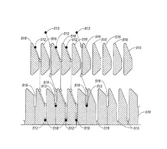
cement as the
casing is secured within the wellbore. This type of casing window assembly,
however,
presents several disadvantages such as, for example, a larger outside diameter
around the
casing where the outer sleeve is connected, a lower pressure rating and it
must be milled
before drilling the lateral wellbore.
[0006] Other conventional casing window assembly designs include a section
of
casing with a pre-milled window through the side of the casing for entry by a
tool and an
inner steel sleeve connected to the pre-milled window to protect the inside of
the casing from
debris and cement as the casing is secured within the wellbore. Although this
type of
assembly provides a better seal for the pre-milled window and may have a
higher pressure
rating, it requires a separate trip to retrieve before drilling the lateral
wellbore. This extra-
separate trip to remove the inner sleeve can cost upwards of $100,000.00 to
retrieve from a
deep wellbore.
[0007] Other components of a conventional casing window assembly may
include,
for example, a mandrel for carrying a whipstock and/or a completion deflector
and a separate
orienting member secured below a pre-milled window in the casing for orienting
the
1
=
CA 02956236 2017-01-25
whipstock and/or the completion deflector at the proper lateral position and
depth that is
substantially the same lateral position and depth as the pre-milled window.
The orienting
member thus, orients the whipstock and/or completion deflector in order that
the
milling/drilling tool may enter the formation through the pre-milled window at
the proper
lateral position and depth. Because most conventional orienting members
provide orientation
both for a lateral position and depth at the same time, achieving a proper
lateral position and
depth in deeper wells can be time consuming and difficult due to the amount of
torque
imposed on the drilling string. In other words, as the drilling string is
turned slowly from the
top, the torque from turning the drilling string builds up and causes the
bottom of the drilling
string, where the whipstock and/or completion deflector are located, to turn
rapidly in deeper
applications. This often prevents finding the proper lateral position, which
is not known until
the torque is transmitted back up the drilling string.
SUMMARY OF THE INVENTION
[0008] The present invention overcomes one or more of the prior art
disadvantages by
using an improved casing window assembly to complete a lateral wellbore
without milling
through any part of the assembly.
[0009] In one embodiment the present invention includes a casing window
assembly,
comprising: i) a tubular casing sleeve having an inside diameter, an outside
diameter and an
opening between the inside diameter and the outside diameter forming a casing
window, the
inside diameter including a recessed wall profile for receipt of a portion of
an expandable
wall and a recess for receipt of a portion of a securing element; and ii) an
inner sleeve
releasably secured within the casing sleeve by the expandable wall or the
securing element
and having an inside diameter, an outside diameter and a wall between the
inside diameter
and the outside diameter, a portion of the wall forming the expandable wall
and another
portion of the wall including a portion of the securing element.
[0010] In another embodiment, the present invention includes a method for
installing
a casing window assembly, comprising: i) lowering the casing window assembly
into a main
wellbore to a predetermined depth, the casing window assembly including a
tubular casing
sleeve with a casing window and an inner sleeve releasably secured within the
casing sleeve
at a pre-released position adjacent the casing window; ii) releasing the inner
sleeve from the
casing sleeve; and iii) releasably securing the inner sleeve within the casing
sleeve at a post-
released position below the casing window.
2
CA 02956236 2017-01-25
[0011] In yet another embodiment, the present invention includes a casing
window
assembly, comprising: i) a tubular casing sleeve having an inside diameter, an
outside
diameter and an opening between the inside diameter and the outside diameter
forming a
casing window; ii) a mandrel having an upper end and a lower end, at least one
of the upper
end of the mandrel and the lower end of the mandrel including an expandable
stop and
orienting-key; and iii) an orienting member secured within the casing sleeve
below the casing
window, the orienting member including a plurality of guiding elements
separated by a
plurality of slots, the plurality of slots including an orienting slot that
directs the mandrel to a
lateral position that is substantially the same as a lateral position of the
casing window and
that permits the mandrel to be lowered to a depth that is substantially the
same as a depth of
the casing window.
[0012] These and other objects, features and advantages of the present
invention will
become apparent to those skilled in the art from the following description of
the various
embodiments and related drawings.
BRIEF DESCRIPTION OF THE DRAWINGS
[0013] The invention will be described with reference to the accompanying
drawings,
in which like elements are referenced with like reference numbers, and in
which:
[0014] FIG. 1 is a cross-sectional view illustrating an upper end of an
inner sleeve for
one embodiment of a casing window assembly according to the present invention.
[0015] FIG. 2 is a cross-sectional view illustrating a middle section of
the inner
sleeve for the casing window assembly in FIG. I.
[0016] FIG. 3 is a cross-sectional view illustrating a lower end of the
inner sleeve for
the casing window assembly in FIG. I.
[0017] FIG. 4 is a cross-sectional view illustrating a lower end of a
casing sleeve for
the casing window assembly in FIG. I.
[0018] FIG. 5 is a cross-sectional elevation view illustrating a casing
sleeve, a
mandrel and an orienting member for another embodiment of a casing window
assembly
according to the present invention.
[0019] FIG. 6A is a schematic view illustrating the mandrel and the
orienting
member for the casing window assembly in FIG. 5 wherein the mandrel is
positioned at a
proper depth and orientation.
3
CA 02956236 2017-01-25
[0020] FIG. 6B is a schematic view illustrating the mandrel and the
orienting
member for the casing window assembly in FIG. 5 wherein the mandrel is rotated
from an
improper depth to a proper depth and orientation.
DETAILED DESCRIPTION OF THE PREFERRED EMBODIMENTS
[0021] In the following detailed description of the preferred embodiments,
reference
is made to the accompanying drawings that form a part hereof, and in which is
shown by way
of illustration specific preferred embodiments in which the inventions may be
practiced.
These embodiments are described in sufficient detail to enable those skilled
in the art to
practice the invention, and it is to be understood that other embodiments that
may be utilized
and that logical changes may be made without departing from the spirit and
scope of the
present invention. The claimed subject matter thus, might also be embodied in
other ways, to
include structures, steps and combinations similar to the ones described
herein, in conjunction
with other present or future technologies, The following detailed description
is therefore, not
to be taken in a limiting sense, and the scope of the present invention is
defined only the
appended claims.
[0022] Referring now to FIGS. 1-4, a cross-sectional view illustrates one
embodiment
of an improved casing window assembly 100. The casing window assembly 100
includes an
upper end of an inner sleeve 116 (FIG. 1), a middle section of the inner
sleeve 116 (FIG. 2)
and a lower end of the inner sleeve 116 (FIG. 3). The casing window assembly
also includes
a lower end of a tubular casing sleeve 102 (FIG. 4).
[0023] The casing sleeve 102 has an inside diameter 104, an outside
diameter 106 and
an opening between the inside diameter 104 and the outside diameter 106
forming a casing
window, which may be pre-milled. The inside diameter 104 of the casing sleeve
102 includes
a recessed wall profile 108 for receipt of a portion of an expandable wall 110
and a plurality
of recesses for receipt of a portion of a respective securing element. The
recessed wall profile
108 of the casing sleeve 102 and the expandable wall 110 are circumferential.
The inner
sleeve 116 is releasably secured within the casing sleeve 102 by the
expandable wall 110
and/or one or more securing elements, and has an inside diameter 118, an
outside diameter
120 and a wall 122 between the inside diameter 118 and the outside diameter
120. A portion
of the wall 122 forms the expandable wall 110 and another portion of the wall
122 includes a
portion of a securing element 112 and a portion of another securing element
113. The another
portion of the wall 122 may further include a counter-securing element 114 and
another
counter-securing element 115 opposite the securing element 112 and opposite
the another
4
CA 02956236 2017-01-25
securing element 113, respectively. The securing element 112 and the counter-
securing
element 114 are preferably positioned above the casing window. The another
securing
element 113 and the another counter-securing element 115 are preferably
positioned below
the casing window. The number of securing elements may depend on a number of
factors
including, for example, the design of the casing window assembly 100 and the
conditions
under which it may be used.
[0024] The inside diameter 118 of the inner sleeve 116 includes a recessed
wall
portion 126 with an opening for receipt of the portion of the securing element
112 and a
portion of the counter-securing element 114, The inner sleeve 116 is
releasably secured to
another inner sleeve 128 by a shear element 130 and/or by another shear
element 131. The
another inner sleeve 128 includes an outside diameter 132 with a recess 134
and another
recess 135 for receipt of a portion of the securing element 112 and a portion
of the counter-
securing element 114, respectively.
[0025] Each recess on the inside diameter 104 of the casing sleeve 102 and
each
respective securing element 112, another securing element 113, counter-
securing element
114, and another counter-securing element 115 releasably secures the inner
sleeve 116 within
the casing sleeve 102 at a pre-released position as illustrated in FIG. 1. The
expandable wall
110 and the recessed wall profile 108 of the casing sleeve 102 releasably
secure the inner
sleeve 116 within the casing sleeve 102 at a post-released position. The
expandable wall 110
and recessed wall profile 108 may therefore, be designed to withstand a
predetermined force
to releasably secure the inner sleeve 116 within the casing sleeve 102 at the
post-released
position. An end of the recessed wall profile 108 includes a shoulder 124 as
illustrated in
FIG. 4. The shoulder 124 secures the inner sleeve 116 substantially near the
post-released
position when a force causes the inner sleeve 116 to release from the post-
released position
and move toward the shoulder 124,
[0026] The outside diameter 120 of the inner sleeve 116 includes a
circumferential
recess above the easing window for receipt of a seal 136 and another
circumferential recess
below the casing window for receipt of another seal 138. The seal 136 and the
another seal
138 improve a high pressure rating for the casing window assembly 100 wherein
each seal
may be an 0-ring or any other well known sealing element. Additional seals
137, 139 may be
included to further improve the high-pressure rating of the casing window
assembly 100. The
casing window assembly 100 therefore, may be rated with a high pressure rating
of at least
8,500 psi due to its unique design. Each seal 136, 137, 138, 139 and/or the
inner sleeve 116
substantially prevent fluid communication between a main wellbore and within
the inside of
CA 02956236 2017-01-25
the casing sleeve 102 adjacent the casing window when the inner sleeve 116 is
releasably
secured at the pre-released position. In this manner, the area inside the
casing sleeve 102 may
be protected from debris and cement as the casing is secured within the main
wellbore.
[0027] The casing window assembly 100 may be installed within a main
wellbore by
lowering the casing window assembly 100 into the main well bore to a
predetermined depth.
The inner sleeve 116 is releasably secured within the casing sleeve 102 in the
pre-released
position at the predetermined depth adjacent the casing window. The inner
sleeve 116 may be
released from the casing sleeve 102 by a downward force imposed by a tool on
an end of the
another inner sleeve 128 thus, shearing the shear element 130 and/or the
another shear
element 131 and causing the another inner sleeve 128 to release and travel
downward within
the recessed wall portion 126 until a portion of the securing element 112
and/or a portion of
the counter-securing element 114 drop into the recess 134 and the another
recess 135,
respectively. In this manner, the securing element 112 and/or the another
securing element
114 fall out of the recesses on the inside diameter 104 of the casing sleeve
102. Likewise, the
another securing element 113 and the another counter-securing element 115 fall
out of the
recesses on the inside diameter 104 of the casing sleeve 102. Installation of
the casing
window assembly 100 may be completed by releasably securing the inner sleeve
116 within
the casing sleeve 102 at the post-released position below the casing window.
Once the inner
sleeve 116 is released from the casing sleeve 102 in the manner thus
described, the inner
sleeve 116 travels downward within the casing sleeve 102 until the expandable
wall 110
enters the recessed wall profile 108 of the casing sleeve 102 and expands
thus, releasably
securing the inner sleeve within the casing sleeve 102 at the post-released
position below the
casing window. In this manner, a separate trip into the main wellbore is not
necessary to
retrieve the inner sleeve 116. Alternatively, however, the inner sleeve 116
may be removed
from the casing window assembly 100 in the main wellbore.
[0028] A bushing may be positioned within the recessed wall profile 108 of
the
casing sleeve 102 to prevent drill cuttings and/or other debris from settling
in the recessed
wall profile 108 and on the shoulder 124 that would prevent the inner sleeve
116 from
moving to the post-released position. The bushing may be made from cardboard
or some
other well known compressible material that would prevent drill cuttings
and/other debris
from settling in the recessed wall profile 108 and on the shoulder 124 while
permitting the
inner sleeve 116 to compress or otherwise displace the bushing in order that
inner sleeve 116
may travel to the post-released position.
6
CA 02956236 2017-01-25
[0029] Once the casing window assembly 100 is installed, the casing window
assembly 500 described in reference to FIGS. 5-6 may be used to orient a tool
within the
casing sleeve 102 at a lateral position that is substantially the same as the
lateral position of
the casing window and to lower the tool to a depth that is substantially the
same as the depth
of the casing window. Once the tool reaches the proper lateral position and
depth, the tool
may be positioned through the casing window when the inner sleeve 116 is
releasably
secured at the post-released position.
[0030] Referring now to FIG. 5, a cross-sectional elevation view
illustrates another
embodiment of an improved casing window assembly 500, The casing window
assembly 500
includes a tubular casing sleeve 502, a mandrel 508 and an orienting member
514. The casing
sleeve 502 has an inside diameter 504 and an outside diameter 506. The lower
end of the
mandrel 508 may include a plurality of expandable stop and orienting-keys 512.
The plurality
of expandable stop and orienting-keys 512 are preferably spring actuated or
may be actuated
by any other well known mechanical, electrical, hydraulic or other means.
[0031] The mandrel 508 has an upper end opposite the lower end. The upper
end of
the mandrel 508 may include another plurality of expandable stop and orienting-
keys 513,
depending on the preferred incremental orientation of the mandrel 508. The
another plurality
of expandable stop and orienting-keys 513 are preferably spring-actuated or
may be actuated
by any other well known mechanical, electrical, hydraulic or other means. The
upper end of
the mandrel 508 may also include a whipstock or a completion deflector
positioned above the
plurality of expandable stop and orienting-keys 512 and the another plurality
of expandable
stop and orienting-keys 513.
[0032] The orienting member 514 is secured within the casing sleeve 502
below the
casing window, however, may be one integral component. The orienting member
514
includes a plurality of guiding elements 516 separated by a plurality of slots
518. The
plurality of slots 518 include a plurality of orienting slots that direct the
mandrel 508 to a
lateral position that is substantially the same as the lateral position of the
casing window and
that permit the mandrel 508 to be lowered to a depth that is substantially the
same as the
depth of the casing window. Each of the plurality of expandable stop and
orienting-keys 512
and each of the another plurality of expandable stop and orienting-keys 513
may be
positioned within a respective one of the plurality of slots 518 upon contact
with one of the
plurality of guiding elements 516. The plurality of orienting slots therefore,
first direct the
mandrel 508 to the lateral position that is substantially the same as the
lateral position of the
casing window before permitting the mandrel 508 to be lowered to the depth
that is
7
CA 02956236 2017-01-25
substantially the same as the depth of the casing window. If the plurality of
expandable stop
and orienting-keys 512 and/or the another plurality of expandable stop and
orienting-keys
513 are not properly aligned within the orienting slots, then the mandrel 508
cannot be
lowered to the proper depth and must be rotated again until the plurality of
expandable stop
and orienting-keys 512 and the another plurality of expandable stop and
orienting-keys 513
are properly aligned within the orienting slots. The proper lateral position
for the mandrel 508
is thus, located to position the whipstock or completion deflector at a
lateral position that is
substantially the same as the lateral position of the easing window before
lowering the
mandrel 508, with the whipstock or completion deflector, to a depth that is
substantially the
same as the depth of the casing window. In this manner, the proper lateral
position is
conveniently determined without the delay associated with conventional
orienting members
caused by torque on the drilling string. The preferred number of the plurality
of slots 518,
including orienting slots, may depend on the preferred number of the plurality
of expandable
stop and orienting-keys 512 and/or the preferred number of the another
plurality of
expandable stop and orienting-keys 513.
[0033] Referring now to FIG. 6A, a schematic view of the mandrel 508 and
the
orienting member 514 for the casing window assembly 500 is illustrated wherein
the mandrel
is positioned at a proper depth and orientation. For purposes of clarity, the
paths of three of
the plurality of expandable stop and orienting-keys 512 and two of the another
plurality of
expandable stop and orienting-keys 513 are illustrated. The plurality of slots
518 are
equidistantly spaced around a circumference of the orienting member 514 in
increments of
72 , however, may be spaced in any other preferred manner or increment.
Because the
mandrel 508 is aligned at a proper depth and orientation each of the three of
the plurality of
expandable stop and orienting-keys 512 are positioned within a respective one
of the plurality
of slots 518 that are referred to as the orienting slots.
[0034] Referring now to FIG. 6B, a schematic view of the mandrel 508 and
the
orienting member 514 for the casing window assembly 500 is illustrated wherein
the mandrel
is rotated from an improper depth to a proper depth and orientation. Because
the mandrel 508
is misaligned at an improper depth, it must be rotated axially upward once to
index the
mandrel 508 to a proper depth and orientation as illustrated by the path of
one of the plurality
of expandable stop and orienting-keys 512 and the path of one of the another
plurality of
expandable stop and orienting-keys 513. The design of the orienting member 514
and its
plurality of guiding elements 516 may be referred to as an indexing or walking
J slot
configuration that allows the mandrel 508 to be effectively picked up and
automatically
8
CA 02956236 2017-01-25
indexed to the next one of the plurality of slots 518 for a new orientation
until the proper
depth and orientation are reached. If the next orientation is correct, then
the mandrel 508 will
move further downward providing an indication at the surface that the mandrel
508 is at the
correct depth and orientation.
9