Note: Descriptions are shown in the official language in which they were submitted.
CA 02956371 2017-01-27
Brief Description of the Drawings
Fig 1 shows a typical configuration of the current invention that is lowered
into a borehole.
Figure 2 shows a typical arrangement of equipment uphole of the tool that is
lowered into the
borehole.
Figure 3 is a view of the assembled bottom hole assembly.
Figure 4 is a sectioned view of the bottom hole assembly showing interior
components.
Figure 5 is a close up view of the end of the bottom hole assembly.
Figure 6 is a cross section view of the bottom hole assembly.
Figure 7 is a general layout view of one embodiment.
Figure 8 is an expanded view of figure 7.
Figures 9-11 show the stroker mechanism and details of the hydraulic and
electronic versions.
Figure 12 is a friction reducing tool.
Detailed Description of the Invention:
Figure 1 shows a typical configuration of tools and other items that are run
into a borehole in the
earth on a coiled tubing system. Collectively, this is called the milling
assembly (10). From the
distal end is a bit (12), which can be a tricone bit, diamond bit, or any
other bit that is well
known in the art. Different bits may be used depending upon the types of
material that are to be
milled out. Next is a rotational power source (14) for the bit, typically a
progressive cavity
motor, or "mud motor". Other types of sources of rotation can be used, such as
hydraulic motors,
or submersible electric motors. The motorhead assembly (16) and hydraulic jar
(18) are well
known items and are commonly used in conjunction with coiled tubing
operations. As is
commonly known, it is desirable to run a release tool as part of the motorhead
assembly (16) so
that the motor (14) and the mill (12) can be detached and left in the borehole
if they become
stuck. A hydraulic release tool is actuated by circulating a ball down to the
release tool and
pressuring up to shift a sleeve which in turn allows a collet to flex so that
dogs can uncouple
from an undercut in the body. The ball must be small enough to pass through
the coiled tubing
(22), the connector (24), the BHA (20), the optional jars (18), and the double
flapper check
valves. A tension release is actuated by pulling the release into tension by a
predetermined
amount. If the release tool in the motorhead assembly (16) is actuated, the
double flapper check
valves maintain well control by preventing wellbore fluids from flowing to
surface up the coiled
tubing. A circulation sub is also incorporated into the motorhead assembly
that allows for
circulation out the side of the motorhead assembly using flow ports. These
flow ports are
actuated by circulating a ball down to a seat in a shiftable sleeve and
pressuring up to slide a
sleeve that in tern exposes flow ports in the side of the body. The ball must
be small enough to
CA 02956371 2017-01-27
pass through the coiled tubing (22), the connector (21), the BHA (20), the
optional jars (18), the
double flapper check valves, and the release tool. In some instances, a
hydraulic jar may not be
used. In horizontal boreholes, it is common to add a vibration device that
uses a water hammer or
Coanda effect to break static friction of the coiled tubing along the
wellbore. The vibration
devise could be positioned anywhere in the milling assembly but is often
located between the
motor (14) and the motorhead assembly (16). Those skilled in art will
appreciate that the order of
components is not fixed, and can be varied with components added or deleted
according to
operating conditions.
The mud motor (14) is driven by a motive fluid pumped from surface, often
water with an
additive package, but other fluids known in the art such as drilling muds,
inert gases, diesel fuel,
or commingled liquids and gases can be used.
The bottomhole assembly (BHA) 20 is the sub that contains the various sensors
and instruments
to collect various parameters of interest that relate to the milling and
borehole conditions, such as
pressure, temperature, vibration levels and directions, stress and force
levels and directions and
others. Within this sub is a pressure sensor array. This contains multiple
pressure sensors such
that the differential fluid pressure across the milling assembly (10) can be
measured. The milling
assembly (10) is considered the coiled tubing connector (24), BHA (20),
optional hydraulic jar
(18), motorhead assembly (16), optional vibration device (126), drilling bit
(12) The differential
pressure is used to determine the condition of the mud motor (14), and can
determine if the
motor has stalled due to excessive axial force being applied by the coiled
tubing. The pressure
sensors can also be used for determining the pressures within the annulus of
the borehole, and
within the coiled tubing.
Also contained on BHA (20) are accelerometers placed on multiple axis used in
conjunction with
a data processing module. Together, these can measure the vibration signature
of the bit as it is
turning and milling the plug or other obstruction and determine if the bit has
contacted the
obstruction to be milled, if it has stalled, or if the cutting rate is in an
optimal range. Further
parameters that can be determined are the bit condition, such as if it is
getting dull, debris size
from the cuttings coming off the obstruction being milled, cutting
effectiveness of the bit and the
rotational speed of the bit. A further parameter than can be deduced is the
condition of the mud
motor, as excessive vibration can indicate a worn motor. By sampling various
frequencies the
condition of different parts of the milling assembly can be monitored as has
been well
understood for predictive maintenance of large rotating machinery for several
years.
Other sensors contained within BHA (20) are temperature sensors, to measure
the fluid and
borehole temperatures at bottomhole conditions. Strain gauges and other
sensors are present such
that the weight on bit can be measured, as well as the axial force within the
coiled tubing.
Typically, multiple strain gauges are used in different orientations such that
forces in axial and
torsional directions can be measured. Other sensors known in the art may be
used to measure the
forces on the coiled tubing and the bit. These strain gauges, combined with
the accelerometers
can determine the advancement rate of the coiled tubing within the borehole.
The weight on bit is
essential to know if contact is being made with the obstruction to be milled,
and in combination
with measuring rotational speed can determine if the bit is actually
contacting the obstruction to
be milled out. A frequent cause of non productive time on coiled tubing
operations currently is
CA 02956371 2017-01-27
there is no effective way to determine when the bit is contacting the
obstruction, so the bit could
be turning and not doing any milling. Similarly, it could be pressed so hard
against the
obstruction that the mud motor stalls and cannot turn the bit, so again no
milling is being
accomplished. Alternatively, the milling bit may not be engaged sufficiently
with the
obstruction; this condition leads to premature bit wear and, potential damage
to the stator in the
motor due to over speeding, and inefficient milling. Similar to metalworking
operations using
conventional machine tools, there is an optimum combination of rotational
speed and feed rate of
the cutting surface against the item to be machined to produce an optimum
cutting rate and tool
life.
The mono conductor E coil (22) is a data linking apparatus that can convey
data to and from the
surface as well as power. These types of E Line are well known in the art and
can be fibre optic,
electric copper wires, carbon based conductors and other materials and
combinations. Due to the
length and diameter of the coiled tubing, the data transmission rates are
limited at the present
time. There is also a limit to the amount of power that can be transmitted to
the BHA. Owing to
these constraints, a data processor is provided within the BHA (20), such that
the data from the
sensors can be processed in real time and the desired data or processed
information can be
transmitted to surface for use in an automatic optimization processing
operation, or displayed for
an operator at a control panel. Other embodiments may have the processed
information sent to a
remote viewing location, such as a head office in a distant city for
evaluation by Engineers and
other personnel such as the clients.
In general, it is desirable to have the data processed in real time, such that
the operations can be
adjusted as soon as possible to optimize the milling rate, but it is not
necessary that it be done in
real time. When the data from the processor within the BHA is utilized in an
automatic system
to adjust the milling parameters it is desirable to utilize the data in real
time. Typically, the
automatic system is a computer than can adjust the pumping rate of the motive
fluid, which in
turn will affect the rotational speed of the mud motor and bit, and can adjust
the weight on bit by
increasing or decreasing the force applied to the coiled tubing by the
injector head, to ensure that
sufficient force is applied at the bit to cut effectively, but not so much
force that the mud motor
stalls and cannot rotate the bit. The information can be used in a feedback
loop to continuously
adjust the parameters to ensure an optimum cutting rate and tool life.
In a different embodiment the adjustment system could be done manually by
operators on
surface in response to watching the displayed information that has been
transmitted to surface by
the BHA's data processor, with a similar objective to achieve the optimum
cutting rate.
In yet another embodiment, there is no real time connection to surface. The
downhole data is
recorded and viewed at a later time to determine if non productive milling
time could have been
reduced.
In a further embodiment, a friction reducing tool (126) is added to the
milling assembly. These
types of tools are well known in the art where they produce vibration when the
motive fluid is
pumped through them. By this means, the coiled tubing vibrates and can
overcome friction in the
hole to allow further penetration into the horizontal section of the borehole.
A disadvantage with
CA 02956371 2017-01-27
the current tools is they are active whenever the motive fluid is pumped
through them, even
when their effect is not needed or wanted.
In some prior art tools, valves are comprised of shifting sleeves. These
sleeves are shifted open
by dropping balls which engage the sleeve, but it takes time for the ball to
flow with the fluids to
reach the tool, and it is not 100% effective in engaging the sleeve because of
operator error or
other factors. In addition, once a sleeve is shifted, it usually cannot be
returned to its previous
position by dropping another ball.
In the current embodiment, the data collected can detect when the coil is
advancing in the
borehole under applied axial force from surface, and when it is stuck in hole,
or about to become
stuck. Under those conditions, a valve can be opened by electric or other
means to allow motive
fluid to pass through the friction reducing tool to activate it and unstick
the coiled tubing. When
the coiled tubing is free and moving the port can be closed and the motive
fluid can bypass the
friction reducing tool deactivating it so the effect is turned off. This will
prolong the life of the
coil and other associated components, while increasing the accuracy of the
data collected by the
plurality of sensors. A further benefit is the energy of the motive fluid is
no longer being
consumed by the friction reducing tool, but can be applied to the mud motor to
turn the milling
bit and increase the milling rate compared to a conventional arrangement of
friction reducing
tool and mud motor operating simultaneously. Yet a further benefit is the tool
can be turned on
or off as many times as needed, without the need to drop balls and wait for
them to be effective.
In a further embodiment, an electric release mechanism is incorporated into
connector sub (24),
such that in the event of becoming stuck in hole, the BHA can be released from
the coil and left
behind, while the coiled tubing can be retrieved to surface. In the current
art, if a ball can't be
circulated to the release tool, or the predetermined over pull can't be
achieved at the distal end of
the coiled tubing, the coiled tubing must be cut off at surface and the distal
end left in the hole.
Workover rigs are then used to retrieve the coiled tubing where possible. This
is an expensive,
time consuming, and destructive process, requiring the entire reel of coiled
tubing required to be
scrapped and a replacement sourced before well service operations can be
resumed.
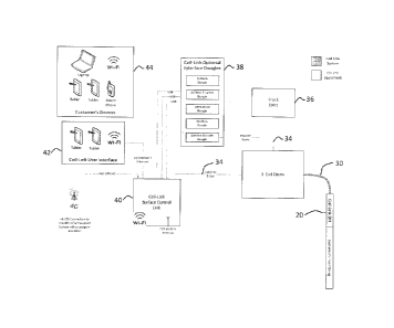
In Figure 2, the BHA 20 is shown in schematic form connected to the E-coil
(30). A conductor
(34) is contained within the coiled tubing. E-Coil (30) can consist of a fibre
optic, copper, or
other known conductors or combinations thereof placed within coiled tubing
that can transmit
power and or signals and data between the BHA (20) and the surface.
Surrounding the conductor
(34) is a protective sheath to protect the conductor from abrasion and to
carry any tension forces.
Once on surface, the E-Coil (30) is wound on the E-Coil drum (32) as a storage
medium. The E-
Coil conductor (34) is connected to the data collection and processing devices
(36), through
interface devices (38) and (40). These are typical devices known in the art
for the purposes of
data collection and transmitting for use by other devices. From interface
device (40) the data can
be transmitted either wirelessly or by wired means to display devices (42), or
to a computer for
further use and process adjustment operations. The data can be displayed on a
remote device
(44), which can be a customer device on location, or in another location such
as an office in a far
away city.
CA 02956371 2017-01-27
In figure 3 is shown details of the bottomhole assembly (20). It consists of
an anchor packoff
(50), attached to the sensor chassis (52). Threadingly engaged to the chassis
and covering the
electronics is a sensor chassis sheath (56). Within the sheath (56) is a
pressure port (58) that
allows fluid communication to the pressure transducer inside the BHA. On the
distal end is a
crossover sub (60) that allows the BHA (20) to be attached to other subs or
pipe via standard
oilfield threads (62). Wrench flats (54) are provided at appropriate points to
facilitate assembly
and disassembly of the tool.
In figure 4 the outer sheath (56) is removed and interior detail is shown. A
pressure bulkhead
section (70) is provided at the uphole portion of the tool to provide
isolation between the
electrical cavity (72) and the fluids that flow through the center of the tool
to ensure that the
electronics operate in a dry environment. Within the electrical cavity (72)
are printed circuit
boards (74) that contain circuits for data gathering, processing and
transmission. Pressure
transducers (76) are also included within the electrical cavity to measure the
downhole pressure
of the annulus. A mounting surface (80) is provided upon which strain gauges
are mounted to
enable weight on bit, applied torque and other parameters to be measured and
fed to the data
collection and processing circuits. This mounting surface (80) is covered by
the sheath 56 and is
in the dry area. In conjunction with the pressure bulkhead (70) is an anchor
pack off sub (71)
where the wireline can attach to the tool.
Figure 5 shows the distal end of the BHA, with detail of the strain gauge
mounting surface (80),
pressure port (58) and pressure transducer (76).
Figure 6 is a cross sectional view of figures 4 and 5, with greater detail of
the internal parts. The
pressure bulkhead section (70) has a fluid passage (90) for passing motive
fluid, as well as
allowing balls to pass through. balls are used in many downhole tools to
perform certain
functions, such as opening sliding sleeves or ports. A 15/16" ball (92) is
shown to illustrate that a
ball can pass through the BHA.
Within the pressure bulkhead is a wireline type packoff (94). This provides a
fluid seal between
the receiving bore (96) and the wireline, or other information and/or power
conductor (not
shown). The wireline is well known in the art and consists of outer armour,
inner insulation and
armour, and at the center one or more conductors for carrying power and or
information. The
conductor(s) can be copper, fibre optics, or other suitable known materials. A
packoff
compression screw (98) compressed packing elements to form a leak tight seal.
The anchor
elements anchor the wireline to the receiving bore, such that it will not pull
out under tension. A
bulkhead fitting, such as manufactured by Kemlon is used to pass the conductor
out of the
receiving bore and into the electrical cavity (72). The conductor passes
through the bulkhead
fitting (100) and attaches to contacts (102). From there, contact is made to
the appropriate places
on the circuit boards (74).
CA 02956371 2017-01-27
The outer sheath (56) attaches to the pressure bulkhead (70) through threads
(104), and provides
a fluid tight joint through seals (106). The outer sheath (56) does not engage
the pressure
bulkhead (70), a gap (108) is left between the outer sheath (56) and the
pressure bulkhead (70) to
ensure that the strain gauges will record accurate measurements of axial load
and torque applied
to the drill bit.
Figure 7 is a general arrangement of the components in a subterranean
formation (120). From the
uphole side, are e-coil (22), coiled tubing connector (24), bha (20), coiled
tubing jars (18),
followed by a motor head assembly (16), a friction reducing tool (126), an
optional stroker tool
(128), a mud motor (14) and a milling bit (132). Jars (18) are well known and
are designed to
provide impact forces in an axial direction to help release the coiled tubing
if it should be come
stuck in the hole. Jars exert an impact load at the distal end of the coiled
tubing which is not
dampened by coiled tubing stretch and friction if a similar upward or downward
load were to be
applied at surface using the coiled tubing injector. The friction reducing
tool (126) as described
above is a vibrating and shaking device that causes pressure pulsations within
the coiled tubing.
These pressure pulsations cause the coiled tubing to vibrate and its entire
length. This vibration
breaks the static friction between the coiled tubing and the adjacent wall of
the wellbore so that
coiled tubing can be inserted further into the wellbore. The mud motor (14) is
a well known
device that converts the flow and pressure of the motive fluid into rotational
motion used to turn
the drilling or milling bit, depending upon the desired operation. The mud
motor (14) can be
considered the engine that drives the bit (132). The choice and pairing of mud
motor and bit
would be known to those skilled in the art.
The motor head assembly (16) consists of a safety valve, typically a double
flapper check valve,
a release tool, and circ sub. Optionally, a coil connector may be included. A
coil connector is a
device to connect the end of the coiled tubing to other tools. An example is a
dimple connecter,
but other configurations are known.
The bridge plug (130) is the object to be removed by the bit (132) and the
other tools described
previously collaborate to optimize the milling operation. Bridge plugs are
well known, and can
take many different configurations and materials, bridge plugs are generally
set in wellbores that
are cased with casing (134) but variations are commercially available for use
in open hole.
Figure 8 includes many of the components outlined in figure 7, with the
addition of the
perforations 142.
In figure 9, a stroker mechanism or linear actuator (128) is shown in an
embodiment that is
hydraulically actuated. Within an outer body housing (150) is a flow diverter
(152) which diverts
fluid around the hydraulic reservoir (154) and hydraulic pump module (156).
The fluid flowing
through the passage (151) is motive fluid, typically water but may be drilling
mud or other
CA 02956371 2017-01-27
known fluids. The hydraulic system used for actuating the piston (160) within
the housing (150)
is an isolated system using hydraulic oil, or other suitable fluid, and this
oil does not come into
contact with the motive fluid flowing the tool through passage (151).
From hydraulic reservoir (154), the fluid is pressurized and pumped by the
pump module (156).
The pump module is controlled by the data collection and processing devices
(36), from surface,
or by an integral processor. Known means of communication between the downhole
components
are used, such as local area radio or wireless communications protocols.
Communication to
surface is by the means described in figure 2.
From the pump module (156) the fluid flows though hydraulic passages (160) to
act on the piston
(158) urging it in a downhole direction. The distal end of the piston (158)
had standard oilfield
threads (162) to connect the mud motor and bit as shown in figures 7 and 8. By
means of
manipulating the output pressure of the pump module (156) the force acting on
the piston (158)
and thus the milling bit (132) in contact with the obstacle to be milled,
typically a bridge plug
(130). By means of manipulating the force on bit, milling parameters such as
cutting rate can be
optimized.
To counter rotational forces from the bit, the anti rotation surfaces (164)
are not round, but a
geometric shape, such as hexagonal. Other suitable shapes can be used. A
retaining nut (166) is
used to retain one or more followers (165) that fit between the retaining nut
and the anti rotation
surfaces (164). The inner surface of the follower (165) is adapted to be
substantially the same
shape as the piston (158) an the outer surface is adapted to engage the inner
surface of the
retaining nut (166). In a preferred embodiment, there are 2 followers (165). A
keyway (167) is
cut into the retaining nut (166) and into each follower, locking the follower
to the retaining nut
with a key placed into the keyway (167) and preventing rotation of the
follower (165) relative to
the retaining nut (166)
Piston rings (168) provide a fluid tight seal between the piston and the outer
housing (150), and
the inner tube (170). The sealing surface the seals (168) engagement is round,
unlike the anti
rotation surfaces (164) that are non round.
In figure 10 the motive fluid passages (151) are shown in greater detail. The
piston (158) can be
urged to the right in the orientation of the drawing under hydraulic force
generated by the
hydraulic pump module (156). The piston (158) can be retracted by opening a
check valve within
the pump module (156) and the fluid can flow back to the hydraulic reservoir
(154) by fore
applied to the distal end of the piston (158). This force can be applied by
the injector on surface
urging the coiled tubing further into the hole, and the piston and further
equipment attached to
threads (162) abutting a bridge plug (130) or any other obstruction
encountered downhole.
An alternative embodiment of the linear actuator (128) is detailed in figure
11. In place of the
hydraulic means to displace the piston, an electric linear actuator module
(180) is provided.
Connected to the electric linear actuator (180) is an actuator shaft (182)
that moves in an axial
direction. The shaft (182) engages a piston (184), such that the piston (184)
can be extended or
retracted by the linear actuator (180) to change the weight on bit applied. In
this embodiment the
anti rotational features function identically to the hydraulic embodiment
described above.
CA 02956371 2017-01-27
An embodiment of a friction reducing tool is shown in Figure 12. Within an
outer housing (200)
is a rotor (202). The rotor (202) rotates as it is driven by an electric motor
and controller
assembly (204) and holes in the rotor allow or block the passage of fluid
through the at least one
fluid passage (206). The effect of the rotating rotor (202) is to act as a
flow interrupter such that
the fluid exiting the tool pulses, rather than flowing continuously. The
pulses of fluid create
vibrations, especially since the at least one fluid flow passage(s) (206) are
not located on the axis
of the tool, so the fluid impinging on the end of the tool section to exit on
axis further enhances
the vibration effect. As described hereinabove, the vibrations are desirable
to enhance the
penetration of the coiled tubing into the horizontal section of a wellbore in
a subterranean
formation, and are also useful to help release the coiled tubing if it should
become stuck in the
wellbore.
Due to the energy consumption and possible fatigue induced failures, it is
desirable to have the
vibration effect only operate when needed, rather than continuously. The
electric controller
assembly (204) is in contact with the other data processor located on adjacent
tools by similar
means to the other data gathering and processing devices, and in contact with
the surface if
desired by the same means as the other devices described hereinabove.
While the preferred embodiment has been set forth above, those skilled in art
will appreciate that
the scope of the invention is significantly broader than as outlined in the
claims which appear
below.