Note: Descriptions are shown in the official language in which they were submitted.
CA 02956476 2017-01-26
WO 2016/030856 PCT/1B2015/056513
FLEXIBLE POUCH WITH MEMORY SUPPORT STRIPS AND
METHODS OF PRODUCING AND USING SAME
CROSS REFERENCE TO RELATED APPLICATIONS/INCORPORATION BY REFERENCE
STA _______________________________ lEMENT
[0001] The subject application claims benefit under 35 USC 119(e) of U.S.
provisional
application serial no. 62/042,435, filed August 27, 2014; the entire contents
of which are
expressly incorporated herein by reference.
STATEMENT REGARDING FEDERALLY SPONSORED RESEARCH AND
DEVELOPMENT
[0002] Not Applicable.
BACKGROUND
[0003] Various types of packaging for products (such as, but not limited
to, food items)
are well known in the art. In particular, flexible pouches are currently used
in the packaging of a
wide variety of products, from food and beverage products to cleaning supplies
and other
household items. Although flexible pouches are in wide usage, there are some
drawbacks to
their display. First, packaged products produced using these flexible pouches
are not as stable as
other types of product packaging (such as, but not limited to, boxes and other
substantially
shape-sustaining containers), and thus require additional shelf manipulation
to be displayed and
maintained in the desired upright position. In addition, when products
packaged in flexible
pouches are handled, they generally lose their original shape and can even
have the appearance
of being crushed. As consumers consider certain products packaged in flexible
pouches, they
may return the packaged products to the shelf/display unit in a crumbled
state. Therefore, to
achieve a desired visual appearance of in-store shelf displays (or other in-
store display units),
continual monitoring and multiple shelf manipulations are required, thereby
resulting in
CA 02956476 2017-01-26
WO 2016/030856 PCT/1B2015/056513
2
increased manual labor costs; however, even the actual shelf manipulation
process can further
hamper the undesirable, crushed appearance of the packaged products produced
using flexible
pouches.
[0004] Therefore, there is a need in the art for new and improved flexible
pouches that
can be substantially retained in their original, upright shape upon handling.
It is to such pouches,
packaged products and kits formed therefrom, as well as methods of producing
and using same,
that the presently disclosed inventive concept(s) is directed.
BRIEF DESCRIPTION OF THE DRAWINGS
[0005] Figure 1 is a perspective view of a flexible pouch of the prior
art.
[0006] Figure 2 is a perspective view of one embodiment of a flexible
pouch constructed
in accordance with the presently disclosed inventive concept(s).
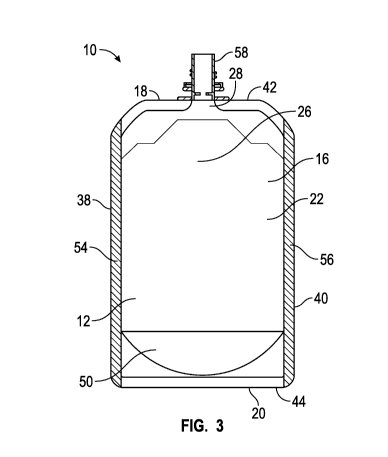
[0007] Figure 3 is a cross-sectional view of the flexible pouch of Figure
2 taken along
line 3-3, wherein the flexible pouch is in a substantially flattened
condition.
[0008] Figure 4 is another cross-sectional view of the flexible pouch of
Figure 2 taken
along line 4-4, wherein the flexible pouch is in a substantially opened
condition.
[0009] Figure 5 is a perspective view of another embodiment of a flexible
pouch
constructed in accordance with the presently disclosed inventive concept(s).
[0010] Figure 6 is a cross-sectional view of the flexible pouch of Figure
5 taken along
line 6-6, wherein the flexible pouch is in a substantially flattened
condition.
[0011] Figure 7 is another cross-sectional view of the flexible pouch of
Figure 5 taken
along line 7-7, wherein the flexible pouch is in a substantially opened
condition.
[0012] Figure 8 is a cross-sectional view of another embodiment of a
flexible pouch
constructed in accordance with the presently disclosed inventive concept(s).
[0013] Figure 9 is another cross-sectional view of the flexible pouch of
Figure 8.
DETAILED DESCRIPTION
[0014] Before explaining at least one embodiment of the presently
disclosed inventive
concept(s) in detail, it is to be understood that the presently disclosed
inventive concept(s) is not
CA 02956476 2017-01-26
WO 2016/030856 PCT/1B2015/056513
3
limited in its application to the details of construction and the arrangement
of the components or
steps or methodologies set forth in the following description or illustrated
in the drawings. The
presently disclosed inventive concept(s) is capable of other embodiments or of
being practiced or
carried out in various ways. Also, it is to be understood that the phraseology
and terminology
employed herein is for the purpose of description and should not be regarded
as limiting.
[0015] Unless otherwise defined herein, technical terms used in connection
with the
presently disclosed inventive concept(s) shall have the meanings that are
commonly understood
by those of ordinary skill in the art. Further, unless otherwise required by
context, singular terms
shall include pluralities and plural terms shall include the singular.
[0016] All patents, published patent applications, and non-patent
publications mentioned
in the specification are indicative of the level of skill of those skilled in
the art to which this
presently disclosed inventive concept(s) pertains. All patents, published
patent applications, and
non-patent publications referenced in any portion of this application are
herein expressly
incorporated by reference in their entirety to the same extent as if each
individual patent or
publication was specifically and individually indicated to be incorporated by
reference.
[0017] All of the articles and/or methods disclosed herein can be made and
executed
without undue experimentation in light of the present disclosure. While the
articles and methods
of the presently disclosed inventive concept(s) have been described in terms
of preferred
embodiments, it will be apparent to those of skill in the art that variations
may be applied to the
articles and/or methods and in the steps or in the sequence of steps of the
method described
herein without departing from the concept, spirit, and scope of the presently
disclosed inventive
concept(s). All such similar substitutes and modifications apparent to those
skilled in the art are
deemed to be within the spirit, scope, and concept of the presently disclosed
inventive
concept(s).
[0018] As utilized in accordance with the present disclosure, the
following terms, unless
otherwise indicated, shall be understood to have the following meanings:
[0019] The use of the word "a" or "an" when used in conjunction with the
term
"comprising" in the claims and/or the specification may mean "one", but it is
also consistent with
the meaning of "one or more," "at least one," and "one or more than one." The
use of the term
CA 02956476 2017-01-26
WO 2016/030856 PCT/1B2015/056513
4
"or" in the claims is used to mean "and/or" unless explicitly indicated to
refer to alternatives only
or that the alternatives are mutually exclusive, although the disclosure
supports a definition that
refers to only alternatives and "and/or." Throughout this application, the
term "about" is used to
indicate that a value includes the inherent variation of error for the device,
the method being
employed to determine the value, or the variation that exists among the study
subjects. For
example, but not by way of limitation, when the term "about" is utilized, the
designated value
may vary by plus or minus twelve percent, or eleven percent, or ten percent,
or nine percent, or
eight percent, or seven percent, or six percent, or five percent, or four
percent, or three percent,
or two percent, or one percent. The use of the term "at least one" will be
understood to include
one as well as any quantity more than one, including but not limited to, 2, 3,
4, 5, 10, 15, 20, 30,
40, 50, 100, etc. The term "at least one" may extend up to 100 or 1000 or
more, depending on
the term to which it is attached; in addition, the quantities of 100/1000 are
not to be considered
limiting, as higher limits may also produce satisfactory results. In addition,
the use of the term
"at least one of X, Y, and Z" will be understood to include X alone, Y alone,
and Z alone, as well
as any combination of X, Y, and Z. The use of ordinal number terminology
(i.e., "first,"
"second," "third," "fourth," etc.) is solely for the purpose of
differentiating between two or more
items and is not meant to imply any sequence or order or importance to one
item over another or
any order of addition, for example.
[0020] As used in this specification and claim(s), the words "comprising"
(and any form
of comprising, such as "comprise" and "comprises"), "having" (and any form of
having, such as
"have" and "has"), "including" (and any form of including, such as "includes"
and "include") or
"containing" (and any form of containing, such as "contains" and "contain")
are inclusive or
open-ended and do not exclude additional, unrecited elements or method steps.
[0021] The term "or combinations thereof- as used herein refers to all
permutations and
combinations of the listed items preceding the term. For example, "A, B, C, or
combinations
thereof- is intended to include at least one of: A, B, C, AB, AC, BC, or ABC,
and if order is
important in a particular context, also BA, CA, CB, CBA, BCA, ACB, BAC, or
CAB.
Continuing with this example, expressly included are combinations that contain
repeats of one or
more item or term, such as BB, AAA, AAB, BBC, AAABCCCC, CBBAAA, CABABB, and so
CA 02956476 2017-01-26
WO 2016/030856 PCT/1B2015/056513
forth. The skilled artisan will understand that typically there is no limit on
the number of items
or terms in any combination, unless otherwise apparent from the context.
[0022] As used herein, the term "substantially" means that the
subsequently described
event or circumstance completely occurs or that the subsequently described
event or
circumstance occurs to a great extent or degree. For example, when associated
with a particular
event or circumstance, the term "substantially" means that the subsequently
described event or
circumstance occurs at least 80% of the time, or at least 85% of the time, or
at least 90% of the
time, or at least 95% of the time. The term "substantially adjacent" may mean
that two items are
100% adjacent to one another, or that the two items are within close proximity
to one another but
not 100% adjacent to one another, or that a portion of one of the two items is
not 100% adjacent
to the other item but is within close proximity to the other item.
[0023] The term "associate" as used herein will be understood to refer to
the direct or
indirect connection of two or more items.
[0024] The term "shelf-stable" as used herein refers to the ability of a
food product to be
safely stored and sold in a sealed container at room temperature while still
having a useful shelf
life in which the taste and nutritional aspects (i.e., nutritional integrity,
nutritional potency, etc.)
of the product is retained. Examples of periods considered to be a "useful
shelf life" include, but
are not limited to, at least about two months, at least about three months, at
least about four
months, at least about five months, at least about six months, and longer.
[0025] The term "complete meal" as used herein refers to a meal that is
designed to
provide one nutritionally-balanced serving; that is, it is not necessary to
combine the complete
meal with another food product to provide a meal. The term "incomplete meal"
thus refers to a
meal not satisfying the requirements of a complete meal, but forming a portion
thereof; that is, a
complete meal is formed upon combining two or more incomplete meals.
[0026] Turning now to the presently disclosed inventive concept(s),
certain embodiments
thereof are directed to a flexible pouch containing one or more memory support
strips that are
disposed along at least a portion of a vertical side thereof. Certain other
embodiments of the
presently disclosed inventive concept(s) are directed to packaged products
produced using such
flexible pouches and kits and assemblies containing such flexible pouches,
while other additional
CA 02956476 2017-01-26
WO 2016/030856 PCT/1B2015/056513
6
embodiments are directed to methods of production and use of the above
flexible pouches,
packaged products, kits, and/or assemblies. The presently disclosed inventive
concept(s)
possesses many benefits over the prior art. First, the flexible pouches
disclosed or otherwise
contemplated herein have greater stability than the pouches of the prior art.
In addition, the
flexible pouches disclosed or otherwise contemplated herein require less
monitoring and shelf
manipulation for display and maintenance in the desired upright position. In
addition, the
flexible pouches disclosed or otherwise contemplated herein will substantially
retain their
original shape upon handling and will not have the appearance of being
crumbled or crushed.
Therefore, the flexible pouches disclosed or otherwise contemplated herein
provide a more
desirable visual appearance of in-store shelf displays while decreasing the
need for continual
monitoring and shelf manipulations, thereby decreasing manual labor costs.
[0027]
Turning now to the Drawings, a squeezable flexible pouch of the prior art is
shown in Figure 1. As can be seen, handling of the squeezable flexible pouch
has resulted in
distortions in a sidewall of the flexible pouch that provide a sort of
"crushed" appearance thereto.
Because of these distortions, the flexible pouch may not be stable in an
upright position and may
require a certain amount of manipulation to increase the stability thereof
when display on a shelf
(or other display unit) is desired. In addition, the flexible pouch may have
to be manipulated
again if handled by a consumer and returned to the display. The required
manipulation results in
increased manual labor costs associated with the visual appearance of the
display; in addition,
the stabilities of the flexible pouches, as well as the configuration in which
a plurality of pouches
are disposed on a shelf (or other display unit), affect the number of flexible
pouches that may be
displayed on a shelf (or other display unit).
[0028] In
contrast, the presently disclosed inventive concept(s) overcomes these
disadvantages and defects of the prior art by providing a structure to the
flexible pouches that
better retains the original shape of the flexible pouches and thus provides
greater stability to the
flexible pouches when they are disposed in an upright, displayed condition.
Certain
embodiments of the presently disclosed inventive concept(s) will be described
herein below with
reference to the Drawings.
CA 02956476 2017-01-26
WO 2016/030856 PCT/1B2015/056513
7
[0029] Shown in Figures 2-4 is one embodiment of a flexible pouch
constructed in
accordance with the presently disclosed inventive concept(s). The flexible
pouch is indicated by
the general reference numeral 10. The flexible pouch 10 includes a sidewall 12
that is formed
from a first panel 14 (Figures 2 and 4) and a second panel 16 (Figures 3 and
4). The flexible
pouch 10 further includes an upper end 18 and a lower end 20, while the
sidewall 12 has an inner
surface 22 and an outer surface 24; in addition, the inner surface 22 of the
sidewall 12 defines a
receiving space 26 that may extend substantially between the upper end 18 and
the lower end 20
of the flexible pouch 10. The upper end 18 has an opening 28 extending
therethrough that
provides access to the receiving space 26.
[0030] The first panel 14 has a first side edge 30, a second side edge 32,
an upper edge
34, and a lower edge 36, while the second panel 16 has a first side edge 38, a
second side edge
40, an upper edge 42, and a lower edge 44. The first side edge 30 of the first
panel 14 and the
first side edge 38 of the second panel 16 are connected to one another and
peripherally sealed
substantially along the lengths thereof to form a first vertical side fin seal
46 of the flexible
pouch 10. Likewise, the second side edge 32 of the first panel 14 and the
second side edge 40 of
the second panel 16 are connected to one another and peripherally sealed
substantially along the
lengths thereof to form a second vertical side fin seal 48 of the flexible
pouch 10. Figure 3
illustrates the flexible pouch 10 in a substantially flattened condition,
while Figures 2 and 4
illustrate the flexible pouch 10 in a substantially open condition.
[0031] While the flexible pouch 10 is shown in Figures 2-4 as being formed
from first
and second panels 14 and 16 and with first and second vertical side fin seals
46 and 48 formed
therein, it will be understood that other methods of forming a flexible pouch
that has seal(s)
formed at different locations and/or has different type(s) of seal(s) formed
therein are well
known to a person of ordinary skill in the art. Therefore, it will be
understood that the flexible
pouches of the presently disclosed inventive concept(s) are not limited to the
particular seal
structures shown herein; rather, flexible pouches produced by different
methods that result in
different seal location(s) and/or type(s) of seal(s) also fall within the
scope of the presently
disclosed inventive concept(s), so long as the flexible pouches so produced
are capable of
CA 02956476 2017-01-26
WO 2016/030856 PCT/1B2015/056513
8
functioning in accordance with the presently disclosed inventive concept(s)
(i.e., are capable of
substantially retaining an upright, vertical position upon display and/or
handling).
[0032] The lower end 20 of the flexible pouch 10 has a gusset 50 formed
therein. The
lower edges 36 and 44 of the first and second panels 14 and 16, respectively,
are connected to the
gusset 50 in the lower end 20 of the flexible pouch, substantially along the
widths thereof.
Alternatively or in addition thereto, the first and second panels 14 and 16
may be connected to
the gusset 50 at one or more points above the lower edges 36 and 44,
respectively, thereof.
While Figure 3 illustrates the gusset 50 as being inwardly folded when the
flexible pouch 10 is in
a substantially flattened condition, it will be understood that the gusset 50
may be provided with
any configuration that allows the lower end 20 to function in accordance with
the presently
disclosed inventive concept(s); that is, the gusset 50 may be provided in any
configuration that
allows the flexible pouch 10 to substantially remain in an upright position.
Therefore, the
inwardly folded gusset 50 of Figure 3 should not be regarded as limiting.
[0033] In one particular, non-limiting example, the flexible pouch 10 is
an upstanding
flexible pouch that is capable of being disposed in an upright, vertical
orientation and remaining
so oriented by virtue of the structure of the flexible pouch 10 (and/or any
product disposed
thereon) when a gusseted lower end 20 of the flexible pouch 10 is in an
expanded condition;
however, in alternative embodiments, a flexible pouch may assume other
configurations, as will
be evident to a person of ordinary skill in the art, given the disclosure
provided herein as well as
knowledge available in the art. Thus, these alternative embodiments also fall
within the scope of
the presently disclosed inventive concept(s), so long as the flexible pouch is
capable of
functioning as described or otherwise contemplated herein. In another
particular, non-limiting
example, the flexible pouch is an upstanding, squeezable flexible pouch.
[0034] The flexible pouch 10 may be formed in any manner known in the art
or
otherwise contemplated by a person having ordinary skill in the art, so long
as the flexible pouch
can function in accordance with the presently disclosed inventive concept(s).
Methods of
forming flexible pouches are well known in the art and are well within the
knowledge of a
person having ordinary skill in the art. Therefore, no further description on
the production
methods that may be employed is deemed necessary.
CA 02956476 2017-01-26
WO 2016/030856 PCT/1B2015/056513
9
[0035] In a similar manner, any materials known in the art or otherwise
contemplated by
a person having ordinary skill in the art may be utilized in the construction
of the flexible pouch
10, so long as the flexible pouch 10 is capable of functioning in accordance
with the presently
disclosed inventive concept(s). In addition, the first and second panels 14
and 16 and the gusset
50 of the flexible pouch 10 may each be formed of the same or separate
materials. Each of these
materials may include a single layer of material or a plurality of the same or
different layers of
material; when multiple layers are present, they may be laminated or co-
extruded or otherwise
combined. For example, but not by way of limitation, at least a portion of the
inner surface 22 of
the sidewall 12 may be formed of a first material, while at least a portion of
the outer surface 24
of the sidewall 12 may be formed of a second material (which may be the same
or different from
the first material); in addition, at least a portion of the gusset 50 in the
lower end 20 of the
flexible pouch 10 may be formed of a third material, wherein the third
material may be the same
or different from the first and/or second materials. Examples of materials
that may be utilized in
accordance with the presently disclosed inventive concept(s) include, but are
not limited to,
nylon; foil; a polyester (including, but not limited to, an oriented
polyester, such as oriented or
biaxially oriented polyethylene terephthalate (PET)); a polyolefin, such as
but not limited to,
polypropylene (PP) or polyethylene (PE) (including, but not limited to, low
density polyethylene
(LDPE) and linear low density polyethylene (LLDPE)); ethyl vinyl alcohol
(EVOH) and EVOH
copolymers; combinations, laminates, and/or extrusions of any of the above;
and the like.
However, other materials that may be used in the construction of flexible
pouches are well
known in the art and can easily be contemplated by a person having ordinary
skill in the art, and
therefore these materials also fall within the scope of the presently
disclosed inventive
concept(s).
[0036] In particular non-limiting examples, the flexible pouch 10 may be
formed of a
polymeric material, such as but not limited to, a polymeric material that is
Bisphenol A (BPA)¨
free and/or a polymeric material that is recyclable and/or renewable. In
addition, the material(s)
from which the flexible pouch 10 is constructed may be gas permeable and/or
gas impervious,
depending on the product(s) to be packaged in the flexible pouch 10. Further,
the materials
from which the flexible pouch 10 is constructed may also have one or more
coatings/lacquers
CA 02956476 2017-01-26
WO 2016/030856 PCT/1B2015/056513
applied thereto, based on the type of product(s) to be packaged in the
flexible pouch 10. For
example, but not by way of limitation, the materials may be provided with a
liquid-
resistant/liquid-proof coating, a gas impervious coating, an insulated
coating, and/or other type
of coating that increases the shelf-life of the product packaged within the
flexible pouch 10.
[0037] In one particular embodiment, as shown in Figures 2-4, the upper
edge 34 of the
first panel 14 and the upper edge 42 of the second panel 16 are connected to
one another along a
portion of the widths thereof to form the upper end 18 of the flexible pouch
10. A portion of the
upper edges 34 and 42 are left unconnected to one another so as to form the
opening 28 in the
upper end 18 of the flexible pouch 10 through which contents disposed therein
can be dispensed.
In addition, the flexible pouch 10 may further include a cap 52 (or other type
of closure/sealing
and/or opening device) that is releasably attached to the opening 28 in the
upper end 18 of the
flexible pouch 10. However, the illustration of the cap 52 is for purposes of
illustration only and
should not be considered limiting to the presently disclosed inventive
concept(s). For example,
but not by way of limitation, the flexible pouch 10 may be provided with
another type of closure
device, such as but not limited to, a press-to-close/zipper-type or slider
device, that allows for
control of the release of substances through the opening 28 in the upper end
18 of the flexible
pouch 10 and/or allows for closure/resealing of the opening 28 in the upper
end 18 of the flexible
pouch 10. In yet another alternative (and/or in addition to a cap and/or any
type of closure
devices), a dispensing device 58 (such as, but not limited to, a straw, spout,
valve, combinations
thereof, and the like) may be attached to the opening 28 to provide a level of
control to the
release of substances from the flexible pouch 10.
[0038] While the first and second panels 14 and 16 are described herein
above as being
connected to one another along a portion of the upper edges 34 and 42,
respectively, thereof, and
an opening formed through a point of non-connection between the two upper
edges 34 and 42, it
will be understood that, in an alternative embodiment, the first and second
panels 14 and 16 may
be connected to one another at a point below the upper edges 34 and 42,
respectively, thereof in
the formation of the upper end 18 of the flexible pouch 10. Alternatively,
another structure may
be attached in between the first and second panels 14 and 16 and in an area
adjacent to or in
relative proximity to the upper edges 34 and 42, respectively, thereof,
wherein the structure may
CA 02956476 2017-01-26
WO 2016/030856 PCT/1B2015/056513
11
form the upper end 18 of the flexible pouch 10 (either alone or in combination
with the upper
edges 34 and 42 of the first and second panels 14 and 16, respectively). This
additional structure
may be similar to the gusset 50 in the lower end 20 of the flexible pouch 10,
and may assist in
the attachment of one or more closure, opening, resealing, and/or dispensing
devices to the
flexible pouch 10.
[0039] In addition, while the opening 28 is described as being formed in
the upper end
18, it will be understood that an alternative placement of the opening 28
(such, as but not limited
to, within the first panel 14, the second panel 16, the lower end 20, the
first vertical side fin seal
46, the second vertical side fin seal 48, and/or the gusset 50) may be
desired. Therefore,
placement of the opening 28 in one of these alternative locations also falls
within the scope of
the presently disclosed inventive concept(s), so long as such placement does
not affect the
function of the flexible pouch 10 of the presently disclosed inventive
concept(s) (for example,
but not limited to, the ability of the flexible pouch 10 to maintain an
upright orientation upon
display and/or handling).
[0040] The flexible pouch further comprises a first support strip of
material 54 and a
second support strip of material 56. Each of the support strips 54 and 56 is
attached to at least a
portion of the sidewall 12 and extends in a substantially vertical direction
thereon. The support
strips of material 54 and 56 are formed of a pliable but substantially non-
malleable material; in
this manner, each of the support strips 54 and 56 possesses a memory feature
that allows the
support strips 54 and 56 to be slightly moveable when pressure is applied to
the flexible pouch
during handling and/or use thereof; however, the support strips 54 and 56
assume their
original shape upon removal of pressure therefrom and without any substantial
indentations
formed thereon. Therefore, the support strips 54 and 56 allow the sidewall 12
of the flexible
pouch 10 to substantially retain its original shape after being handled and/or
after use thereof.
[0041] The support strips 54 and 56 may be formed of any material that is
of sufficient
rigidity to be pliable but substantially non-malleable; that is, the material
must be capable of
substantially retaining its original shape while having a certain amount of
movement/bendability
in response to pressure applied thereto, but wherein the material returns to
its original shape,
with substantially no indentations or folds formed therein, upon release of
the pressure. In
CA 02956476 2017-01-26
WO 2016/030856 PCT/1B2015/056513
12
particular, non-limiting embodiments, the material from which the support
strips 54 and 56 are
formed may be rigid. In other, non-limiting embodiments, the material may be a
smart material.
[0042] The support strips 54 and 56 may be attached or otherwise
associated with at least
a portion of the sidewall 12 of the flexible pouch 10. The support strips 54
and 56 may be
attached to or otherwise associated with the inner surface 22 and/or the outer
surface 24 of the
sidewall 12. The support strips 54 and 56 may both be attached to one of the
first and second
panels 14 and 16, or one of the support strips 54/56 may be attached to one of
the panels 14/16,
while the other support strip 54/56 is attached to the other panel 14/16. In
addition, at least a
portion of one or both of the support strips 54/56 may be attached to both
panels 14 and 16. In
certain embodiments, the support strips 54 and 56 may be disposed opposite to
one another.
[0043] The support strips 54/56 may be attached or otherwise associated
with the
sidewall 12 by any methods known in the art or otherwise contemplated by a
person having
ordinary skill in the art. For example, but not by way of limitation, the
support strips 54 and 56
may be attached to one or both of the panels 14 and 16 via a bonding material.
In addition, any
of the other seals and/or other attachments disclosed or otherwise
contemplated herein may be
formed via the use of a bonding material.
[0044] The term "bonding material" as used herein will be understood to
refer to any
material that is sufficient to connect two elements to one another; in
particular, the term
"bonding material" will be understood to refer to any material that is
sufficient to connect one of
the support strips of material as disclosed or otherwise contemplated herein
to a sidewall of a
flexible pouch. Examples of bonding materials include, but are not limited to,
adhesives
(including, but not limited to, pressure-sensitive adhesives and cold seal
adhesives), cohesives,
adhesive/cohesive combinations, heat sealable materials (such as, but not
limited to, heat sealing
lacquers or hot melt materials), sonically sealable materials (including, but
not limited to,
ultrasonically sealable materials), vibratory sealable materials, combinations
thereof, and the
like.
[0045] The support strip 54 may extend in a vertical direction and
substantially the entire
length of the sidewall 12 from the upper end 18 to the lower end 20 thereof
(for example, but not
by way of limitation, the support strip 54 may be attached to the first panel
14 and extend
CA 02956476 2017-01-26
WO 2016/030856 PCT/1B2015/056513
13
substantially from the upper edge 34 to the lower edge 36 thereof). Likewise,
the support strip
56 may extend in a vertical direction and substantially the entire length of
the sidewall 12 from
the upper end 18 to the lower end 20 thereof (for example, but not by way of
limitation, the
support strip 56 may be attached to the second panel 16 and extend
substantially from the upper
edge 42 to the lower edge 44 thereof). Alternatively, the support strips 54
and 56 may extend in
a vertical direction over only a portion of the length of the sidewall 12. In
yet another
embodiment, one of the support strips 54/56 may extend in a vertical direction
and substantially
the entire length of the sidewall 12 from the upper end 18 to the lower end
20, while the other
support strip 54/56 may extend in a vertical direction over only a portion of
the length of the
sidewall 12. In addition, each of the support strips 54 and 56 may be
associated with a different
panel 14 or 16, or both of the support strips may be attached to a single
panel 14/16. Therefore,
any association described herein of a particular support strip 54/56 with a
particular panel 14/16
is arbitrary and strictly for the purposes of example only; it should not be
considered limiting of
the presently disclosed inventive concept(s).
[0046] In a particular non-limiting embodiment (and as shown in particular
in Figure 4),
at least a portion of the support strip 54 may be disposed between the first
side edge 30 of the
first panel 14 and the first side edge 38 of the second panel 16 prior to
and/or during the
connection thereof, such that at least a portion of the support strip 54 is
disposed within the first
vertical side fin seal 46 during formation thereof. In addition, at least a
portion of the support
strip 56 may be disposed between the second side edge 32 of the first panel 14
and the second
side edge 40 of the second panel 16 prior to and/or during the connection
thereof, such that at
least a portion of the support strip 56 is disposed within the second vertical
side fin seal 48
during formation thereof. In this manner, the first and second vertical side
fin seals 46 and 48 of
the flexible pouch 10 assume their original shape and disposition upon removal
of pressure
therefrom and thereby allow the flexible pouch 10 to substantially retain its
original shape after
being handled. In this embodiment, one or both of the support strips 54 and 56
may extend
substantially the entire length of the respective vertical side fin seal
46/48, or one or both of the
support strips 54 and 56 may only extend a portion of the length of the
respective vertical side fin
seal 46/48.
CA 02956476 2017-01-26
WO 2016/030856 PCT/1B2015/056513
14
[0047] The flexible pouch 10 may further include one or more colors,
designs, and/or
patterns disposed on at least a portion thereof. The color(s), design(s),
and/or pattern(s) may
include, for example but not by way of limitation, packaging and/or labeling
information
(including, but not limited to, "use by" dates and/or batch codes),
instructions for use,
promotional material, company information, logos/trademarks, combinations
thereof, and the
like. The color(s), design(s) and/or pattern(s) may be disposed on the
flexible pouch 10 (and/or
the material from which the flexible pouch 10 is formed) by any method known
in the art,
including but not limited to, printing, etching, embossing, texturing,
coating, lacquering,
application during extrusion, and the like. The color(s), design(s) and/or
pattern(s) may be
applied separately or simultaneously and/or may be characterized totally or
partially by
pearlescent, translucent, transparent, iridescent, or other similar qualities.
Each of the above-
named characteristics may occur alone or in combination and may be applied to
a portion of the
flexible pouch 10 and/or the material from which the flexible pouch 10 is
formed. Moreover,
when the flexible pouch 10 comprises two or more layers of material, each of
the layers of
material may vary in the combination of such characteristics.
[0048] While Figures 2-4 depict the support strips 54 and 56 as being
disposed within the
vertical side fin seals 46 and 48, respectively, it will be understood that
the support strips 54 and
56 may be disposed at any position on the first and/or second panels 14 and
16. For example,
but not by way of limitation, shown in Figures 5-7 is another embodiment of a
flexible pouch
constructed in accordance with the presently disclosed inventive concept(s).
The flexible pouch
is referenced the reference numeral 10a and is similar to the flexible pouch
10, except that a first
support strip of material 54a and a second support strip of material 56a are
disposed in different
locations when compared to the support strips 54/56 of Figures 2-4. At least a
portion of the first
support strip of material 54a is attached or otherwise associated with a first
panel 14a in a
location other than the portions that are included in a first vertical side
fin seal 46a and a second
vertical side fin seal 48a. Similarly, at least a portion of the second
support strip of material 56a
is attached or otherwise associated with a second panel 16a in a location
other than the portions
that are included in a first vertical side fin seal 46a and a second vertical
side fin seal 48a. In
Figures 6 and 7, the first and second support strips 54a and 56a are depicted
as being disposed
CA 02956476 2017-01-26
WO 2016/030856 PCT/1B2015/056513
substantially along a mid-line of the respective panel 14a/16a; however, this
depiction is for
purposes of illustration only, and it should be understood that any placement
of the first support
strip 54a on the first panel 14a, as well as any placement of the second
support strip 56a on the
second panel 16a, is encompassed within the scope of the presently disclosed
inventive
concept(s).
[0049] In addition, it will be understood that the support strips of
material 54/54a and
56/56a need not be attached or otherwise associated with the inner surface
22/22a of the sidewall
12/12a of the flexible pouch 10/10a (and thus disposed within the receiving
space 26/26a of the
flexible pouch 10/10a). Rather, certain embodiments of the presently disclosed
inventive
concept(s) include flexible pouches that have at least one support strip of
material disposed on an
outer surface thereof. For example, Figures 8-9 depict another embodiment of a
flexible pouch
represented by reference numeral 10b. The flexible pouch 10b is similar to the
flexible pouch 10
of Figures 2-4, except as described herein below. A first support strip of
material 54b and a
second support strip of material 56b are both attached to a second panel 16b
in a manner
whereby the support strips of material 54b and 56b are exposed on an outer
surface 24b of the
sidewall 12b of the flexible pouch 10b. The flexible pouch 10b has a first
vertical side fin seal
46b and a second vertical side fin seal 48b. While in Figures 2-4, the support
strips 54/56 are
shown as being disposed within the respective vertical side fin seal 46/48, in
Figures 8-9, the first
support strip of material 54b is disposed on the outer surface 24b of the
sidewall 12b and
adjacent the first vertical side fin seal 46b, while the second support strip
of material 56b is
disposed on the outer surface 24b of the sidewall 12b and adjacent the second
vertical side fin
seal 48b.
[0050] It will be understood that the support strips of material 54b/56b
may be attached
or otherwise associated with any portion of the outer surface 24b of the
sidewall 12b, and
therefore the attachment/association with the second panel 16b, as shown in
Figures 8-9, is for
purposes of illustration only. While the support strips of material 54b and
56b are depicted in
Figures 8-9 as being attached to a back-side of the flexible pouch 10a, the
support strips of
material 54b and 56b may both be attached to an outer surface of the first
panel 14b in a manner
whereby the support strips of material 54b and 56b are exposed on a front-side
of the flexible
CA 02956476 2017-01-26
WO 2016/030856 PCT/1B2015/056513
16
pouch 10b. Alternatively, one of the support strips of material 54b/56b may be
disposed on the
outer surface of the first panel 14a, while the other support strip 54b/56b
may be disposed on the
outer surface of the second panel 16a. Yet further, one of the support strips
of material 54b/56b
may be attached or otherwise associated with the inner surface 22b of the
sidewall 12b, while the
other support strip 54b/56b may be attached or otherwise associated with the
outer surface 24b of
the sidewall 12b.
[0051] Certain embodiments of the presently disclosed inventive concept(s)
are directed
to methods of producing any of the flexible pouches disclosed or otherwise
contemplated herein.
In one particular, non-limiting embodiment of the method, the first and second
panels are sealed
to one another to form the sidewall of the flexible pouch as well as the first
and second vertical
side fin seals thereof (as described in detail herein above). A gusseted lower
end is attached to
the first and second panels substantially along the widths thereof. In
addition, at least a portion
of the first and second support strips of material are attached to the inner
surface and/or outer
surface of the sidewall and extend in a substantially vertical position
thereon.
[0052] The method may further include the step of disposing a
predetermined quantity of
a product within the flexible pouch and releasably sealing the product
therewithin. Any type of
product(s) may be disposed within the flexible pouch, so long as the pouch is
capable of
functioning as disclosed and/or otherwise contemplated herein. The product(s)
may be shelf-
stable, or the product(s) may be perishable and thus require refrigerated
and/or frozen storage
conditions. In addition, the product may be in a solid, semi-solid, semi-
liquid, liquid, and/or
gaseous form. For example, but not by way of limitation, the product may be
selected from the
group consisting of baby food, juice, fruit and/or vegetable purees, beverages
(milk, coffee,
flavored drinks, etc.), beverage concentrate and/or drink mix, other liquid
products (i.e., oils,
salad dressings, sauces, marinades, vinegar, etc.), condiments (i.e., ketchup,
mustard, relish,
honey, butter, etc.), granulated products (spices, seeds, grains, etc.),
processed meat and/or
poultry, pet food, pet treats, pet supplies, refrigerated/frozen foods, dairy
products, candy and
confectionary items, baking supplies, puddings, creams, vegetables, fruit,
vegetable and/or fruit-
based products (i.e., applesauce), health food products, baked goods, dried
fruits and/or nuts,
snack foods, breakfast foods (cereal, oatmeal, granola, etc.), cleaning and
other household
CA 02956476 2017-01-26
WO 2016/030856 PCT/1B2015/056513
17
supplies, health and beauty products (i.e., cosmetics, creams, lotions,
shampoo/conditioner, soaps
and washes, oils, mouthwashes, etc.), pharmaceutical products, and
combinations thereof.
[0053] The method may further include one or more of the following steps:
releasably
attaching a cap to the opening in the upper end of the flexible pouch;
attaching a device that
allows the opening in the upper end of the flexible pouch to be resealed;
and/or attaching at least
one dispensing device to the opening in the upper end of the flexible pouch.
[0054] In addition, other methods of producing flexible pouches of the
prior art (i.e.,
without support strips attached thereto) are well known in the art. In
addition, methods of
attaching strips of material similar to the support strips of material (as
disclosed or otherwise
contemplated herein) to a material are also well known in the art. Therefore,
any method of
producing a flexible pouch (as disclosed or otherwise contemplated herein)
that is within the skill
of a person of ordinary skill in the art also falls within the scope of the
presently disclosed
inventive concept(s).
[0055] Certain embodiments of the presently disclosed inventive concept(s)
are directed
to a packaged product that includes any of the flexible pouches described or
otherwise
contemplated herein, along with a product disposed within the receiving space
of the flexible
pouch. In particular embodiments, a predetermined quantity of a product may be
disposed
within the receiving space and sealed within the flexible pouch.
[0056] Another embodiment of the presently disclosed inventive concept(s)
is directed to
a method of producing a packaged product as described herein above. In the
method, a
premeasured quantity of a product is disposed within the receiving space of
any of the flexible
pouches described or otherwise contemplated herein and sealed therewithin.
[0057] Another embodiment of the presently disclosed inventive concept(s)
is directed to
a kit containing at least one of the packaged products described herein above
(i.e., a flexible
pouch containing at least one product disposed therein). A kit may include one
or more
packaged products, such as but not limited to, two or more packaged products,
three or more
packaged products, four or more packaged products, five or more packaged
products, six or more
packaged products, seven or more packaged products, eight or more packaged
products, nine or
more packaged products, ten or more packaged products, eleven or more packaged
products,
CA 02956476 2017-01-26
WO 2016/030856 PCT/1B2015/056513
18
twelve or more packaged products, thirteen or more packaged products, fourteen
or more
packaged products, fifteen or more packaged products, sixteen or more packaged
products,
seventeen or more packaged products, eighteen or more packaged products,
nineteen or more
packaged products, twenty or more packaged products, and the like. Each
flexible pouch present
in the kit may be the same, or the kit may contain two or more different
types/sizes of flexible
pouches. In addition, each product packaged in the flexible pouches may be the
same, or the kit
may contain two or more different products.
[0058] The kits of the presently disclosed inventive concept(s) may
further include a
display unit on which at least a portion of the packaged product(s)/kit(s) may
be disposed and
thereby displayed. Display units are well known in the art, and therefore no
further discussion
thereof is deemed necessary.
[0059] The kits of the presently disclosed inventive concept(s) may
further include one or
more sets of instructions. The instructions may explain how to use the kit(s)
for display of the
packaged product(s) present therein and/or how to produce a display assembly
that includes one
or more packaged product(s) of the kit(s) disposed on a display unit. Any type
of format capable
of conveying the desired information (and/or directing a user's attention to a
location where said
information can be found) may be utilized as the instructions described or
otherwise
contemplated herein. Non-limiting examples of formats in which the
instructions may be
provided include written wording and/or pictorial drawings, hardware,
software, a website
address, a bar code (such as but not limited to, a QR code) that is readable
by an imaging
device/code reader, combinations thereof, and the like. The instructions may
contain static
information, or the instructions may be in an interactive form.
[0060] Another embodiment of the presently disclosed inventive concept(s)
is directed to
an assembly. The assembly includes one or more of any of the packaged products
disclosed or
otherwise contemplated herein (and/or one or more of the kits containing same)
and a display
unit on which at least a portion of the packaged product(s)/kit(s) is disposed
and thereby
displayed.
[0061] In particular embodiments of the kits and assemblies of the
presently disclosed
inventive concept(s), the plurality of packaged product(s) are further defined
as a range of food
CA 02956476 2017-01-26
WO 2016/030856 PCT/1B2015/056513
19
and/or beverage products, each being disposed in a flexible pouch constructed
in accordance
with the presently disclosed inventive concept(s). The range includes a
plurality of different
products disposed in flexible pouches that are produced as described herein
above. The range
may include a plurality of individual products and/or a plurality of kits
containing the individual
products. The plurality of products may differ in the types of food disposed
therein.
Alternatively and/or in addition thereto, the plurality of products may differ
in the age
range/stage to which they are directed. For example, but not by way of
limitation, US Published
Application No. US2010/0255114, the entire contents of which are incorporated
herein by
reference, discloses a range of shelf-stable baby food products for meeting
the nutritional needs
of an infant/child at a specific stage of infant development; these stages
include Stage 1 (from
about 4 months to about 6 months), Stage 2 (from about 6 months to about 8
months), Stage 3
(from about 8 months to about 12 months), and Stage 4 (from about 12 months to
about 36
months). Thus, the plurality of products in the range may include a
combination of foods
directed to two or more of Stages 1-4 listed above.
[0062] Yet another further embodiment of the presently disclosed inventive
concept(s) is
directed to a method of providing a range of food and/or beverage products,
each being disposed
in a flexible pouch constructed in accordance with the presently disclosed
inventive concept(s).
The range may include a plurality of individual packaged products and/or a
plurality of kits
containing the individual packaged products. In the method, a range that
includes a plurality of
different food and/or beverage products, each being disposed in a flexible
pouch and produced as
described in detail herein above, are provided. At least two of the products
present in the
plurality of different products differ from one another in the types of food
and/or beverage
products provided and/or the age range/stage to which the products are
directed. The range of
food and/or beverage products in the flexible pouches constructed in
accordance with the
presently disclosed inventive concept(s) is displayed for perusal by
consumers, so that a
consumer can select one or more products from the range. The range of products
is displayed
with a desired visual appearance based upon the structures of the flexible
pouches, which
provide greater stability when in the upright position.
CA 02956476 2017-01-26
WO 2016/030856 PCT/1B2015/056513
[0063] The combinations of any of the method steps described herein above
may be
performed simultaneously or wholly or partially sequentially. In addition, the
exemplary
sequences of method steps provided herein above are for the purposes of
illustration only; it will
be understood that the individual steps, as well as the particular order of
steps, may vary, and the
sequence of steps may be performed in any order, so long as the materials and
packages
described herein are capable of functioning in accordance with the presently
disclosed inventive
concept(s).
[0064] Thus, in accordance with the presently disclosed inventive
concept(s), there has
been provided flexible pouches, packaged products and kits formed therefrom,
as well as
methods of producing and using same, that fully satisfy the objectives and
advantages set forth
herein above. Although the presently disclosed inventive concept(s) has been
described in
conjunction with the specific language set forth herein above, it is evident
that many alternatives,
modifications, and variations will be apparent to those skilled in the art.
Accordingly, it is
intended to embrace all such alternatives, modifications, and variations that
fall within the spirit
and broad scope of the presently disclosed inventive concept(s). Changes may
be made in the
construction and the operation of the various components, elements, and
assemblies described
herein, as well as in the steps or the sequence of steps of the methods
described herein, without
departing from the spirit and scope of the presently disclosed inventive
concept(s).