Note: Descriptions are shown in the official language in which they were submitted.
CA 02957170 2017-02-03
OPTICALLY INTERFACED FLUID DENSITY SENSOR
BACKGROUND
[0001] The fuel that is used in aircrafts has a density that changes with
brand, additives,
temperature and pressure, as well as other factors. Because the density of
aircraft fuel changes in
response to these factors, knowing the volume of fuel aboard an aircraft
doesn't always
sufficiently inform the pilot of the amount of fuel, and therefore the
possible range of flight of
the aircraft. The product of fuel volume and fuel density gives the fuel mass,
which is a better
metric of the amount of fuel carried by the aircraft. Many modern aircrafts
are equipped with
both fuel volume sensors and fuel density sensors.
[0002] Fluid density sensors or fluid densitometers are used to measure the
density of a
fluid. Such sensors can be constructed to exploit different principles of
operation. For example,
one of the oldest ways to measure density is by measuring a pressure
differential between two
bubble tubes vertically oriented in a fluid tank. In this method, the two
bubble tubes are
immersed in the fluid tank. Each of the bubble tubes extends to a different
depth in the fluid
tank. Air is pumped through each of the tubes so as to purge the tube of
fluid, which results in
bubbles being injected at the depth of the bubble tube. The back pressure is
measured for each
of the bubble tubes. The difference between the back pressures of the two
bubble tubes is related
to the density of the fluid in the tank.
[0003] Other methods of measuring a density of a fluid employ various
mechanical
oscillation measurements. For example, a spring may oscillate at a first
resonant frequency when
oscillating in air. But when submersed in a liquid, the spring may oscillate
at a second resonant
frequency. The resonant frequency of oscillation may be indicative of a
density of the fluid in
which the spring resides. Other electromechanical oscillators that vibrate at
a frequency
proportional to the density of the medium surrounding the oscillator can also
be used to measure
fluid density. A vibrating spool densitometer is one such fluid density
transducer. These
vibrating spool densitometers traditionally have electrical interfaces, with
which to communicate
operating power and output signals to a control unit.
[0004] Electrically communicating between a control unit outside of a fuel
tank and an
electromechanical oscillator within a fuel tank can incur risks of electrical
arcing, which in turn
can ignite the fuel within the tank. A short circuit or a lighting strike
involving the electrical
CA 02957170 2017-02-03
lines that connect the fuel density sensor to the controller can have
catastrophic consequences.
Thus, there is a need for eliminating electrical communications between
equipment located
within a fuel tank and controllers located outside the fuel tank.
SUMMARY
[0005] Apparatus and associated methods relate to a fluid density sensor
configured to
optically receive operating power and to optically communicate a measured
fluid density. The
fluid density sensor includes a fluid tight housing separating an interior
cavity from an exterior
environment. The fluid tight housing is configured to prevent a fluid from the
exterior
environment entering the interior cavity. The fluid density sensor includes a
fiber optic
connection port configured to connect to an optical fiber in the exterior
environment while
providing an optical path for light energy to traverse the fluid tight
housing. The light energy is
communicated between the optical fiber and the interior cavity. The fluid
density sensor
includes a fluid density transducer configured to be immersed in the fluid.
The fluid density
transducer generates an electrical output signal indicative of a density of
the fluid. The fluid
density sensor also includes sensor electronics located entirely within the
interior cavity. The
sensor electronics includes an optical power converter configured to convert
the light energy
communicated from the optical fiber to the optical power converter within the
interior cavity via
the fiber optic connection port. The light energy is converted into DC
electrical energy. The
sensor electronics includes an energy storage device configured to store the
converted DC
electrical energy. The sensor electronics includes a signal generator
configured to generate,
using at least a portion of the stored DC electrical energy, an electrical
input signal for use by the
fluid density transducer. The sensor electronics includes a transducer
interface configured to
supply the generated electrical input signal to the fluid density transducer
and to receive the
electrical output signal of the fluid density transducer. The sensor
electronics also includes an
optical signal generator configured to generate a light signal, based on the
received electrical
output signal, the light signal indicative of the density of the fluid.
[0006] Various embodiments relate to a method of suppressing electrical
arcing within a
fuel tank in which a fuel density sensor is located. The method includes
physically isolating
sensor electronics from fuel in the fuel tank via a fluid barrier. The method
includes electrically
isolating the sensor electronics within a cavity from potential high voltage
hazards without the
2
CA 02957170 2017-02-03
cavity. The method includes optically communicating light energy between
without the cavity
and within the cavity. The method includes converting light energy from
without the cavity into
DC electrical energy within the cavity. The method includes storing the
converted DC electrical
energy. The method includes supplying the sensor electronics with operating
power from the
converted DC electrical energy. The method includes determining a density of a
fuel without the
cavity. The method also includes generating a light signal indicative of the
density of the fluid.
[0007] In some
embodiments, a vibrating spool densitometer is configured to optically
receive operating power and to optically communicate a measured fuel density.
The vibrating
spool densitometer includes a fuel tight housing separating an interior cavity
from an exterior
environment. The fuel tight housing is configured to prevent a fuel from the
exterior
environment entering the interior cavity. The vibrating spool densitometer
includes a fiber optic
connection port configured to connect to an optical fiber in the exterior
environment while
providing an optical path for light energy to be communicated from the optical
fiber to the
interior cavity. The
vibrating spool densitometer includes a vibrating spool transducer
configured to be immersed in the fuel. The vibrating spool transducer has a
resonant frequency
indicative of a density of the fuel. The vibrating spool densitometer also
includes sensor
electronics located entirely within the interior cavity. The sensor
electronics includes an optical
power converter configured to convert the light energy communicated from the
optical fiber to
the optical power converter within the interior cavity via the fiber optic
connection port. The
light energy is converted into DC electrical energy. The sensor electronics
includes an energy
storage device configured to store the converted DC electrical energy. The
sensor electronics
includes a signal generator configured to generate, using at least a portion
of the stored DC
electrical energy, an electrical excitation signal for use by the vibrating
spool transducer. The
sensor electronics includes a transducer controller configured to supply the
generated electrical
excitation signal to the vibrating spool transducer and to determine a
resonant frequency of the
vibrating spool transducer. The determined resonant frequency is indicative of
the density of the
fuel. The sensor electronics also includes an optical signal generator
configured to generate a
light signal, based on the determined resonant frequency, the light signal
indicative of the density
of the fuel.
3
55859989-423CA
BRIEF DESCRIPTION OF THE DRAWINGS
[0008] FIG. 1 is a schematic diagram of an exemplary fuel density
sensor located
within a wing tank of an aircraft.
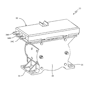
100091 FIG. 2 is a perspective view of an exemplary optically
interlaced fluid density
sensor.
[0010] FIG. 3 is a block diagram of an exemplary optically interfaced
fluid density
sensor.
[0011] FIG. 4 is a block diagram of an exemplary optically interfaced
fluid density
sensor.
[0012] FIGS. 5A-5B are block diagrams of different embodiments of optical
interfaces of an optically interfaced fluid density sensor.
DETAILED DESCRIPTION
[0013] FIG. 1 is a schematic diagram of an exemplary fuel density
sensor located
within a wing tank of an aircraft. In FIG. I, scenario 10 depicts aircraft 12
being struck by
lightning bolt 14. Aircraft 12 has fuel tanks 16 in each of wings 18. Within
each of fuel
tanks 16 are fuel density sensor 20 and fuel volume sensor 22. Fuel density
sensors 20 and
fuel volume sensors 22 may be in communication with fuel monitoring system 24
located in
cockpit 26 of aircraft 12. Fuel density sensors 20 may communicate a measure
of density of
the fuel within fuel tanks 16 via interconnect 28.
100141 If interconnect 28 were a conductive wire type of interconnect,
a large voltage
and/or current could be coupled onto interconnect 28 in response to lightning
bolt 14. A
conductive wire type of interconnect could then carry such a large coupled
voltage and/or
current into fuel tanks 16. In this way, such a conductive wire type of
interconnect can
present a dangerous risk of igniting the fuel within fuel tanks 16. If
interconnect 28 were
instead an optical fiber type of interconnect, such voltages and/or currents
would not be
conductively carried into fuel tanks 16, as optical fibers can have very low
electrical
conductivities.
100151 A fixed quantity of aircraft fuel may have a volume that
changes in response
to various factors. For example, the volume may increase in response to
increasing
temperature and/or decreasing pressure. When thc volume increases in such a
manner, the
density of the fuel
4
CA 2957170 2017-06-23
CA 02957170 2017-02-03
decreases such that the product of the density and the volume is substantially
constant. Thus,
such a product of volume and density may be calculated to provide an accurate
measure of the
mass of fuel within fuel tanks 16. Fuel monitoring system 24 may combine
signals
communicated from fuel density sensors 20 and fuel volume sensors 22 to
calculate the mass of
the fuel contained within fuel tanks 16. For example, the product of a measure
of the volume of
the fuel within fuel tanks 16 and a measure of the density of the fuel within
fuel tanks 16 is a
measure of a mass of the fuel within fuel tanks 16. Such a measurement may be
an important
datum to provide to a pilot. The importance of this datum, however, is not so
great as to justify
compromising aircraft's 10 ability to tolerate lighting strikes or short
circuit failures. Thus,
optically interfacing between fuel density sensors 20 and fuel monitoring
system 24
advantageously permits calculation of this important datum while minimizing a
risk of electrical
arcing within fuel tanks 16.
100161 Fuel density sensors 20 may measure a density of the fuel within
fuel tanks 16
using various techniques. One such technique is by measuring a resonant
frequency of a
vibration or oscillating object immersed in the fuel within fuel tanks 16. The
principle of
operation of many such fuel density measurement devices is that the resonant
frequency changes
in response to changes in the density of the fuel in which the fuel density
measurement device
resides. A vibrating spool densitometer is one such fuel density measurement
device which
operates according to this principle. Some vibrating spool densitometers are
electromechanical
devices and therefore require electrical operating power and generate an
electrical signal
indicative of the density of the fuel in which the vibrating spool
densitometer resides. Thus, an
optical interface should communicate both operating power to the vibrating
spool densitometer
and a signal indicative of the density measurement from the vibrating spool
densitometer.
10017] FIG. 2 is a perspective view of an exemplary optically interfaced
fluid density
sensor. In FIG. 2, a vibrating spool densitometer type of fuel density sensor
20 is depicted.
Exemplary vibrating spool densitometer 20 includes vibrating spool transducer
30, fuel tight
housing 32 and fiber optic connection ports 34A-C. Within fuel tight housing
32 is a sensor
electronics module. Vibrating spool transducer 30 may be mounted within fuel
tank 16 via
mounting flanges 36. Vibrating spool transducer 30 may be mounted at locations
(e.g., at or near
a lower region of a fuel tank) that may contain fuel even in low fuel
conditions, such that
CA 02957170 2017-02-03
vibrating spool transducer 30 remains submerged in the fuel of fuel tank 16.
When so
submerged, accurate measurements of fuel density can be made.
[0018] Fuel tight
housing 32 provides a physical barrier to fuel, thereby preventing fuel
from fuel tank 16 entering an interior cavity, in which the sensor electronics
is located. Fuel
tight housing 32 may be of a clamshell style two-piece construction, for
example. An 0-ring
and/or gasket made of a material that can withstand exposure to fuel may form
a seal between
the two pieces of such a construction. Fuel tight housing 32 may electrically
isolate the sensor
electronics within the cavity from potential high voltage hazards without the
cavity. For
example, fuel tight housing 32 may three-dimensionally surround the interior
cavity within a
dielectric material. In such a configurations, there will be no conductive
feed through paths from
an outside surface to an inside surface of fuel tight housing 32.
[0019] Fuel tight
housing 32 may be formed of dielectric material fully surrounding the
internal cavity. Fuel tight housing 32 may be made of one type of dielectric
material or of two or
more types of dielectric materials, for example. Fuel tight housing 32 may
form a contiguous
and gapless dielectric barrier surrounding the cavity that contains the sensor
electronics. A
thickness and a material may be chosen to meet a dielectric breakdown
specification. For
example, the dielectric breakdown of the fuel tight housing may be 1000 Volts,
or 5000 Volts, or
8000 Volts. The dielectric breakdown specification may be selected to be that
of an expected
value necessary to withstand an anticipated hazard, such as a lightning
strike.
[0020] In the
depicted embodiment, vibrating spool densitometer 20 has three fiber optic
connection ports. In some embodiments, a light energy sufficient for to
provide operating power
to vibrating spool densitometer 20 may require one, two, or more optical
fibers to communicate
from the optical fibers to an electronic system within the cavity. In some
embodiments, one or
more optical fibers may be dedicated to providing operating power to vibrating
spool
densitometer 20, while one or more optical fibers may he dedicated to
providing signal
communication between vibrating spool densitometer 20 and an external
controller. In some
embodiments, both operating power and signal communication may share one or
more optical
fibers.
[0021] In an
exemplary embodiment, a single optical fiber communicates operating
power from a controller to the vibrating spool densitometer 20 as well as
providing signal
communication between the controller and vibrating spool densitometer 20.
Signal
6
CA 02957170 2017-02-03
communication may include communication of an output signal from vibrating
spool
densitometer 20 to the controller of an output signal indicative of a density
of a fuel. Signal
communication may include communication of a control signal and/or a request
signal from the
controller to vibrating spool densitometer 20, for example.
[0022] FIG. 3 is a block diagram of an exemplary optically interfaced fluid
density
sensor. In FIG. 3, vibrating spool densitometer 20 includes vibrating spool
transducer 30, fuel
tight housing 32 and fiber optic connection ports 34A-C. Within fuel tight
housing 32 is sensor
electronics module 38. Sensor electronics module 38 includes: optical
interface 40; optical
power converter/energy storage module 42; power supply 44; sensor
interface/signal
conditioning module 46; controller 48; output driver 50; and LED 52.
[0023] In the depicted embodiment, optical interface 40 facilitates
communication of
light energy from fiber optic connection ports 34A-B to optical power
converter/energy storage
module 42. In some embodiments, optical interface 40 may facilitate
communication of light
energy from more than two fiber optic connection port. In an exemplary
embodiment, optical
interface 40 may facilitate communication of light energy from only one fiber
optic connection
port. In some embodiments, optical interface 40 may facilitate bidirectional
communication of
light energy between one or more fiber optic connection ports and various
electronic and/or
optical components located within fuel tight housing 32.
[0024] FIG. 4 is a block diagram of an exemplary optically interfaced fluid
density
sensor. In FIG. 4, fluid density sensor 54 represents a different embodiment
than the
embodiment depicted in FIG. 3. The FIG. 4 embodiment includes: optical
interface 56; power
distribution module 58; microprocessor 60; sensor interface 62; fluid density
sensor 64; analog-
to-digital converter 66; and memory 68. In the depicted embodiment, optical
interface 56 may
facilitate bidirectional communication of light energy to and from a single
optical fiber
connected to fiber optic connection port 34.
[0025] Optical operating power can be communicated from the optical fiber
connected to
fiber optic connection port 34 to power distribution module 58 via optical
interface 56. Optical
interface 56 may receive light energy from the optical fiber connected to
fiber optic connection
port 34 and convert the received light energy to electrical energy. In an
exemplary embodiment,
optical interface 56 may include one or more photo voltaic cells to convert
light energy to
electrical energy.
7
CA 02957170 2017-02-03
[0026] Optical
interface 56 facilitates communication of an output signal generated by
optically interfaced fuel density sensor 54 to an external receiver. Optical
interface 56 may
receive an electrical output signal indicative of a fluid density from
microprocessor 60. Optical
interface 56 may generate an optical output signal, based on the received
electrical output signal,
and transmit the generated optical output signal to an optical fiber connected
to fiber optic
connection port 34. In some
embodiments, optical interface 56 may facilitate other
communications between an external controller connected to optically interface
fluid density
sensor 54 via one or more optical fibers. In some embodiments, optical
interface 56 may
facilitate bidirectional communication of control signals, measured metrics,
and/or software
updates, for example.
[0027] Light
energy converted by optical interface 56 into electrical energy may be
electrically conducted to power distribution module 58. Power distribution
module 58 may
provide for storage of electrical energy provided by optical interface 56. For
example, power
distribution module 58 may capacitively store electrical energy. Power
distribution module 58
may include one or more batteries for storage of electrical energy. Power
distribution module 58
may provide charging of one or more batteries when received electrical energy
is greater than
energy requirements of circuitry to which power distribution module 58
provides operating
power. Power distribution module 58 may convert electrical energy from one
voltage to one or
more different voltages that may be required by circuitry to which power
distribution module 58
provides operating power. For example, power distribution module may include a
buck and/or
boost switched power converter.
[0028]
Microprocessor 60 may receive operating power from power distribution module
58. Microprocessor 60 may receive program instructions from program memory
locations
within memory 68. Microprocessor may execute the received program instructions
so as to
provide an output signal indicative of a fluid density. And to that end,
microprocessor may
coordinate operations of various optical and/or electronic modules of
optically interfaced fluid
density sensor 54. Microprocessor may communicate with sensor interface 62 to
coordinate
signal between sensor interface 62, fluid density sensor 64, and/or analog-to-
digital converter 66,
for example. Microprocessor 60 and/or sensor interface 62 may, for example,
have a phase-lock
loop for measuring a resonant frequency of fluid density sensor 64.
Microprocessor 60 may save
data collected from various optical and/or electrical components in data
memory of memory 68.
8
CA 02957170 2017-02-03
[0029] FIGS. 5A-
5B are block diagrams of different embodiments of optical interfaces of
an optically interfaced fluid density sensor. In FIG. 5A, optical interface
56a is connected to
optical fiber 70. Optical interface 56a includes diplexer 72, photo voltaic
cell 74 and Light
Emitting Diode (LED) 76. Optical fiber 70 may carry light energy to optical
interface 56a.
Light energy may be directed to photo voltaic cell 74 via diplexer 72. Photo
voltaic cell 74 may
convert the light energy incident thereon to electrical energy. The converted
electrical energy
may then be directed to power distribution module 58 (depicted in FIG. 4).
[0030] LED 76
may receive an electrical output signal from microprocessor 60 (depicted
in FIG. 4). LED may generate an optical output signal in response to the
received electrical
output signal. The generated optical output signal may then be directed to
optical fiber 70 via
diplexer 72. Optical fiber 70 may carry light energy for use as operating
power to optical
interface 56a while providing an optical path for optical output signal from
optical interface 56a.
Such bidirectional communication can be performed simultaneously or can be
performed in a
time multiplexed manner. In some embodiments, command signals may also be
transmitted by
optical fiber 70 from a remote controller to optical interface 56a.
[0031] In FIG.
5B, optical interface 56b depicts an alternate embodiment of optical
interface 56 depicted in FIG. 4. Optical interface 56b is optically coupled to
optical fiber 70.
Optical fiber 70 may transmit light energy from a remote controller to optical
interface 56b.
Optical interface 56b has modulated reflector 78 and photo voltaic cell 80.
Received light
energy is directed to photo voltaic cell 80 via modulated reflector 78.
Modulated reflector 78
may have a reflection coefficient that can be modulated by an electrical
signal, for example. In
the depicted embodiment, the reflection coefficient of modulated reflector 78
is modulated in
response to an electrical output signal, which may be provided by
microprocessor 60 (depicted in
FIG. 4). Modulated reflector may reflect a portion of the received light
energy in response to the
electrical output signal modulating the reflection coefficient, thereby
generating an optical output
signal.
[0032] In an
exemplary embodiment, the reflection coefficient of modulated
reflector 28 may be modulated between a low value and a higher value. For
example, the
reflection coefficient may be modulated between 1% and 10%, for example. A
complementary
transmission coefficient may correspondingly be modulated between 99% and 90%,
respectively.
In such an embodiment, a majority of the received light energy may be used to
provide electrical
9
CA 02957170 2017-02-03
operating power to a fluid density measurement system, while a small portion
of the received
light energy can be reflected as an optical output signal.
[0033] The following are non-exclusive descriptions of possible embodiments
of the
present invention.
[0034] A fluid density sensor is configured to optically receive operating
power and to
optically communicate a measured fluid density. The fluid density sensor
includes a fluid tight
housing separating an interior cavity from an exterior environment. The fluid
tight housing is
configured to prevent a fluid from the exterior environment from entering the
interior cavity.
The fluid density sensor includes a fiber optic connection port configured to
connect to an optical
fiber in the exterior environment while providing an optical path for light
energy to traverse the
fluid tight housing. The light energy is communicated between the optical
fiber and the interior
cavity. The fluid density sensor includes a fluid density transducer in the
housing configured to
be immersed in the fluid. The fluid density transducer generates an electrical
output signal
indicative of a density of the fluid. The fluid density sensor also includes
sensor electronics
located entirely within the interior cavity. The sensor electronics include an
optical power
converter configured to convert the light energy communicated from the optical
fiber via the
fiber optic connection port into DC electrical energy. The sensor electronics
include an energy
storage device configured to store the converted DC electrical energy. The
sensor electronics
include a signal generator configured to generate, using at least a portion of
the stored DC
electrical energy, an electrical input signal for use by the fluid density
transducer. The sensor
electronics include a transducer interface configured to supply the generated
electrical input
signal to the fluid density transducer and to receive the electrical output
signal of the fluid
density transducer. The sensor electronics also include an optical signal
generator configured to
generate a light signal, based on the received electrical output signal. The
light signal is
indicative of the density of the fluid.
[0035] A further embodiment of the foregoing fluid density sensor, wherein
the light
signal indicative of the density of the fluid can be communicated by the
optical signal generator
to the optical fiber line via the fiber optic connection port. A further
embodiment of any of the
foregoing fan drive gear systems, wherein the fiber optic connection port can
be a first fiber optic
connection port. The optical fiber can be a first optical fiber, and the
optical path can be a first
optical path. The fluid density transducer can further include a second fiber
optic connection
CA 02957170 2017-02-03
port configured to connect to a second optical fiber in the exterior
environment while providing a
second optical path for light energy to traverse the fluid tight housing. The
light energy can be
communicated between the second optical fiber and the interior cavity. The
light signal
indicative of the density of the fluid can be communicated from the optical
signal generator to
the second fiber optic fiber via the second fiber optic connection port.
[0036] A further embodiment of any of the foregoing fan drive gear systems,
wherein the
fluid density sensor can be a vibrating spool densitometer. A further
embodiment of any of the
foregoing fan drive gear systems, wherein the optical signal generator can
include an LED. A
further embodiment of any of the foregoing fan drive gear systems, wherein the
optical power
converter can include a photo voltaic cell. A further embodiment of any of the
foregoing fan
drive gear systems, wherein the optical signal generator can be configured to
generate a light
signal indicative of the density of the fluid by modulating a reflection of
the light energy
delivered by the optical fiber. The reflected light signal can be communicated
by the optical
fiber in a direction antiparallel to the direction of the unreflected light
energy carried by the
optical fiber. A further embodiment of any of the foregoing fan drive gear
systems, wherein the
fluid tight housing comprises a dielectric material having a dielectric
breakdown greater than or
equal to 1000 Volts or greater than or equal to 5000 Volts or greater than or
equal to 8000 Volts.
[0037] A method of suppressing electrical arcing within a fuel tank in
which a fuel
density sensor is located includes physically isolating sensor electronics
from fuel in the fuel
tank via a fuel barrier defining a cavity. The method includes electrically
isolating the sensor
electronics within the cavity from potential high voltage hazards outside the
cavity. The method
includes optically transmitting a light energy from a first environment
outside the cavity to a
second environment within the cavity to provide operating power for the sensor
electronics. The
method includes optically transmitting a light signal from the second
environment within the
cavity to the first environment outside the cavity. The light signal is
indicative of fuel density.
The method includes converting the light energy into DC electrical energy
within the cavity.
The method includes storing the converted DC electrical energy. The method
includes supplying
the sensor electronics with operating power from the converted DC electrical
energy. The
method includes determining a density of fuel within the fuel tank outside the
cavity. The
method also includes generating the light signal indicative of the fuel
density.
11
CA 02957170 2017-02-03
[0038] A further embodiment of the foregoing method of suppressing
electrical arcing
within a fuel tank in which a fuel density sensor is located, wherein
optically transmitting light
energy between outside the cavity and within the cavity can include optically
transmitting light
energy carried by an optical fiber external to the cavity to an optical
receiver within the cavity.
A further embodiment of any of the foregoing methods, wherein generating the
light signal can
include modulating an electrical voltage across an LED. A further embodiment
of any of the
foregoing methods, wherein generating the light signal can include modulating
a reflection of
light energy transmitted from without the cavity to within the cavity such
that a portion of the
transmitted light energy is reflected from within the cavity to without the
cavity. A further
embodiment of any of the foregoing methods, wherein electrically isolating
sensor electronics
can include electrical isolation withstanding high voltage hazards of 1000
Volts, 5000 Volts or
8000 Volts.
[0039] A vibrating spool densitometer is configured to optically receive
operating power
and to optically communicate a measured fuel density. The vibrating spool
densitometer
includes a fuel tight housing separating an interior cavity from an exterior
environment. The fuel
tight housing is configured to prevent a fuel from the exterior environment
from entering the
interior cavity. The vibrating spool densitometer includes a fiber optic
connection port
configured to connect to an optical fiber in the exterior environment while
providing an optical
path for light energy to be communicated from the optical fiber to the
interior cavity. The
vibrating spool densitometer includes a vibrating spool transducer in the
housing configured to
be immersed in the fuel. The vibrating spool transducer has a resonant
frequency indicative of a
density of the fuel. The vibrating spool densitometer also includes sensor
electronics located
entirely within the interior cavity. The sensor electronics include an optical
power converter
configured to convert the light energy communicated from the optical fiber via
the fiber optic
connection port into DC electrical energy. The sensor electronics include an
energy storage
device configured to store the converted DC electrical energy. The sensor
electronics include a
signal generator configured to generate, using at least a portion of the
stored DC electrical
energy, an electrical excitation signal for use by the vibrating spool
transducer. The sensor
electronics include a transducer controller configured to supply the generated
electrical
excitation signal to the vibrating spool transducer and to determine a
resonant frequency of the
vibrating spool transducer. The determined resonant frequency is indicative of
the density of the
12
CA 02957170 2017-02-03
fuel. The sensor electronics also includes an optical signal generator
configured to generate a
light signal, based on the determined resonant frequency. The light signal is
indicative of the
density of the fuel.
100401 A further embodiment of the foregoing vibrating spool densitometer,
wherein the
light signal indicative of the density of the fuel can be communicated by the
optical signal
generator to the optical fiber line via the fiber optic connection port. A
further embodiment of
any of the foregoing vibrating spool densitometers, wherein the fiber optic
connection port is a
first fiber optic connection port, the optical fiber is a first optical fiber,
and the optical path is a
first optical path. The vibrating spool densitometer can further include a
second fiber optic
connection port configured to connect to a second optical fiber in the
exterior environment while
providing a second optical path for light energy to traverse the fuel tight
housing. The light
energy can be communicated between the second optical fiber and the interior
cavity. The light
signal can be indicative of the density of the fuel is communicated from the
optical signal
generator to the second fiber optic line via the second fiber optic connection
port. A further
embodiment of any of the foregoing vibrating spool densitometers, wherein the
optical signal
generator comprises an LED. A further embodiment of any of the foregoing
vibrating spool
densitometers, wherein the optical signal generator is configured to generate
a light signal
indicative of the density of the fuel by modulating a reflection of the light
energy delivered by
the optical fiber, the reflected light signal is communicated by the optical
fiber in a direction
antiparallel to the direction of the unreflected light energy carried by the
optical fiber.
100411 While the invention has been described with reference to an
exemplary
embodiment(s), it will be understood by those skilled in the art that various
changes may be
made and equivalents may be substituted for elements thereof without departing
from the scope
of the invention. In addition, many modifications may be made to adapt a
particular situation or
material to the teachings of the invention without departing from the
essential scope thereof.
Therefore, it is intended that the invention not be limited to the particular
embodiment(s)
disclosed, but that the invention will include all embodiments falling within
the scope of the
appended claims.
13