Note: Descriptions are shown in the official language in which they were submitted.
81803297
DISPENSABLE UNIT RETRIEVAL MECHANISM, IDENTIFICATION, AND
NETWORKED NOTIFICATION
[0001]
[0002]
TECHNICAL FIELD
[0003] The present disclosure relates to managing dispensable units such as
health
and wellness consumables, and more particularly to devices, systems, and
methods for the
retrieval, dispensing, management, and notification of dispensables.
BACKGROUND
[0004] There remains a need for improved techniques for retrieving and
dispensing
units from a mixture of one or more dispensable units of arbitrary size,
orientation, texture,
and weight. There also remains a need for detecting properties of dispensable
units in order to
facilitate dispensing, and to provide various fonns of notification relating
to dispensable units.
SUMMARY
[0005] A system enables management of dispensable units by supporting
functions
such as retrieval, scheduled distribution, analysis, notifications, and so
forth. To this end, a
dispensable retrieval mechanism may include a pick-and-place retrieval robot
that is
programmed to carry out blind retrievals of dispensable units using a
retrieval strategy with a
predetermined sequence of retrieval attempts such as a fixed or varying two-
dimensional
retrieval patterns, which may be open loop (i.e., deterministic) or closed
loop (i.e., with
various forms of feedback concerning results of each retrieval attempt).
Techniques may also
include the identification of dispensable units through optical sensors,
weight measurement
devices, and so forth that can detect, e.g., a texture, a shape, and a size of
dispensable units.
Such identification can be used to program retrieval attempts by a retrieval
robot and in the
formulation of the retrieval pattern. Additionally, networked notification
systems for
dispensable units can be used for updating rules or schedules related to the
dispensable units,
1
Date Recue/Date Received 2022-06-15
81803297
or alerting users and remote resources of any potential misuse or hazards of
the dispensable
units.
[0005a] According to one aspect of the present invention, there is provided a
device
comprising: a container; a retrieval arm; a positioner coupled to the
retrieval arm and
actuatable to move the retrieval arm within the container; a sensor configured
to measure a
signal indicative of a level of dispensable units in the container, wherein
the signal indicative
of the level of the dispensable unit is indicative of the force exerted by the
retrieval arm on the
container; and a controller in communication with the positioner and the
sensor, the controller
configured to receive, from the sensor, the signal indicative of the level of
the dispensable
units in the container, and to actuate the positioner to move the retrieval
arm within the
container according to a sequence of retrieval attempts, each retrieval
attempt corresponding
to a different two-dimensional pattern within a horizontal plane through the
container, and
each retrieval attempt carried out at a depth of the container based at least
in part on the signal
indicative of the level of the dispensable units in the container.
[0005b] According to another aspect of the present invention, there is
provided a
method comprising: measuring a signal indicative of a level of dispensable
units in a
container, wherein the signal indicative of the level of the dispensable units
corresponds to
weight of the dispensable units in the container; moving a retrieval arm
within the container
according to a sequence of retrieval attempts of the dispensable units, each
retrieval attempt
associated with a different two-dimensional pattern within a horizontal plane
through the
container; and selectively adjusting a depth of each retrieval attempt within
the container
based at least in part on the signal indicative of the level of dispensable
units in the container.
[0005c] According to another aspect of the present invention, there is
provided a
method comprising: measuring a signal indicative of a level of dispensable
units in a
container, wherein the signal indicative of the level of the dispensable units
in the container
corresponds to force of a retrieval arm on the container; moving a retrieval
arm within the
container according to a sequence of retrieval attempts of the dispensable
units, each retrieval
attempt associated with a different two-dimensional pattern within a
horizontal plane through
the container; and selectively adjusting a depth of each retrieval attempt
within the container
based at least in part on the signal indicative of the level of dispensable
units in the container.
2
Date Recue/Date Received 2022-06-15
81803297
BRIEF DESCRIPTION OF THE DRAWINGS
[0006] The foregoing and other objects, features and advantages of the
devices,
systems, and methods described herein will be apparent from the following
description of
particular embodiments thereof, as illustrated in the accompanying drawings.
The drawings
are not necessarily to scale, emphasis instead being placed upon illustrating
the principles of
the devices, systems, and methods described herein.
[0007] Fig. 1 is a cross-sectional view of a retrieval device.
[0008] Fig. 2 is a cross-sectional view of a retrieval arm.
[0009] Fig. 3 is a cross-sectional view of a retrieval arm.
[0010] Fig. 4 is a flow chart of a method for retrieval of dispensable units.
[0011] Fig. 5 illustrates a two-dimensional retrieval pattern.
[0012] Fig. 6 illustrates a two-dimensional retrieval pattern.
[0013] Figs. 7-10 show various retrieval system configurations.
[0014] Fig. 11 illustrates a system for dispensable unit identification.
[0015] Fig. 12 is a flow chart of a method for dispensable unit
identification.
[0016] Fig. 13 illustrates a system for networked notification for dispensable
units.
[0017] Fig. 14 illustrates another system for networked notification for
dispensable
units.
DETAILED DESCRIPTION
[0018] The embodiments will now be described more fully hereinafter with
reference to the accompanying figures, in which preferred embodiments are
shown. The
foregoing may, however, be embodied in many different forms and should not be
construed as
limited to the illustrated embodiments set forth herein.
[0019] References to items in the singular should be understood to include
items in
the plural, and vice versa, unless explicitly stated otherwise or clear from
the text.
Grammatical conjunctions are intended to express any and all disjunctive and
conjunctive
combinations of conjoined clauses, sentences, words, and the like, unless
otherwise stated or
clear from the context. Thus, the term "or" should generally be understood to
mean "and/or"
and so forth.
3
Date Recue/Date Received 2022-06-15
81803297
[0020] Recitation of ranges of values herein are not intended to be limiting,
referring
instead individually to any and all values falling within the range, unless
otherwise indicated
herein, and each separate value within such a range is incorporated into the
specification as if
it were individually recited herein. The words "about," "approximately," or
the like, when
accompanying a numerical value, are to be construed as indicating a deviation
as would be
appreciated by one of ordinary skill in the art to operate satisfactorily for
an intended purpose.
Ranges of values and/or numeric values are provided herein as examples only,
and do not
constitute a limitation on the scope of the described embodiments. The use of
any and all
examples, or exemplary language ("e.g.," "such as," or the like) provided
herein, is intended
merely to better illuminate the embodiments and does not pose a limitation on
the scope of the
embodiments. No language in the specification should be construed as
indicating any
unclaimed element as essential to the practice of the embodiments.
[0021] In the following description, it is understood that terms such as
"first,"
"second," "above," "below," "top," "bottom," and the like, are words of
convenience and are
not to be construed as limiting terms.
[0022] While the following description provides detailed embodiments of
methods,
systems, and devices for managing dispensable units or items, e.g.,
consumables, it will be
understood that the specific embodiments described herein are provided by way
of example
and not limitation, and that various aspects of this disclosure may have
additional applications
independent from those that are described. For example, the systems and
methods described
herein may be adapted to any environment where liquids, solids, powders,
suspensions, and
the like are controllably dispensed on any predetermined or ad hoc schedule
such as a
chemical, pharmaceutical or life sciences laboratory or a packaging facility
for custom
deliverables. All such variations are intended to fall within the scope of
this disclosure.
[0023] Definitions
3a
Date Recue/Date Received 2022-06-15
CA 02957272 2017-02-03
WO 2016/022714 PCT/US2015/043848
[0024] The terms "item," "unit," "dispensable," and related terms such as
"dispensable
unit," "dispensable item," and the like, are intended to refer broadly to any
item, combination of
items, composition, component, material, compound, object or the like that can
be dispensed in unit
or continuous form.
[0025] While a "dispensable" may be any item that can be dispensed, the term
"consumable" or "consumable unit" is intended to refer to dispensables that
are intended to be
consumed by a user. Consumables are intended to include a wide array of
ingestible consumable
items and form factors for same. For example, consumable units may include one
or more of pills,
capsules, tablets, chewables, lozenges, dissolvables, sprinkles, dissolve-in-
mouth micro-capsules,
orally disintegrating tablets, chewable tablets (including jelly beans,
gummies, and the like), gums,
and so forth, as well as continuous form consumables such as liquids or
powders, solutions, pastes,
suspensions, and combinations thereof. The consumables may also or instead
include items provided
as free powders, powder sachets, liquids, liquid sachets, vials, cups, cases,
other storage forms, and
so forth. More generally, the consumable units may be any composition for
consumption in bulk,
individual, individual pre-packaged, group pre-packaged and/or mixed item
package form. For bulk
form compositions, the "consumable unit" may be a predetermined portion for
dispensing such as a
teaspoon of liquid, a number of pills, a milligram of powder or the like, or a
similar predetermined
portion for dispensing or mixing into a compound locally created for
dispensing prior to or after
dispensing. For bulk form compositions, the "consumable unit" may be a broken
or separated piece
of a continuous whole (e.g., chalk).
[0026] Similarly, the content of each consumable unit may vary significantly
and may
include but is not limited to prescription medication, non-prescription or
over-the-counter
medication, nutritional supplements, vitamin supplements, mineral supplements,
veterinary
medications, veterinary nutritional supplements, and so forth. Consumable
units may also or instead
include food and other items such as sugar, seeds, candies, snacks, pet
treats, or other foods and the
like, as well as any other pharmaceuticals, nutraceuticals, or other
consumable items not identified
above. These consumables that are intended to be ingestible are also referred
to herein as
"ingestibles" or "ingestible units."
[0027] While consumables may include items for consumption in the conventional
sense of
ingestion as described above, consumables may also or instead include
disposable items or the like
that are intended for one time use. Thus, as used herein a "disposable" may be
any consumable
4
CA 02957272 2017-02-03
WO 2016/022714 PCT/US2015/043848
intended for a use other than ingestion. This may, for example, include
disposable medical items
such as dressings, bandages, Band-Aids, gauze, syringes, thermometers,
individually packaged units
of antibacterials and the like, as well as other items such as hearing aids,
contact lenses and so forth
that can be dispensed in individual units for one time use. This may also or
instead include
continuous form items not intended for ingestion including personal care items
such as toothpaste,
toothpicks, soap, sanitizer, moisturizer, cotton swabs and the like, as well
as other household items
such as glue, batteries, latex gloves, and so forth. All such disposables may
be a form of consumable
as those terms are used herein, and consumables may similarly be a form of
dispensable.
[0028] It will be understood that while the foregoing terms (dispensable,
consumable,
ingestible, disposable) may be variously used in this disclosure to describe
embodiments of the
invention, the inventive concept generally applies to any and all such
dispensables, and any
description of one type of dispensable will be understood to refer to all such
dispensables except
where specifically noted to the contrary. Thus for example, a container for
consumable items will be
understood to similarly teach a container for dispensable items, a container
for ingestible items, and
a container for disposable items. As another example, a schedule for delivery
of a medical
prescription will be understood to similarly teach a schedule for delivery of
any dispensable,
ingestible, consumable, and disposable, with suitable modifications being
readily apparent to one of
ordinary skill in the art.
100291 Another term used in the following description is "schedule." As used
herein, this is
intended to refer to any time-based or event-based regime for using
dispensables, or more generally,
any list or other arrangement of times at which possible tasks, events, or
actions related to
dispensables should take place or occur. This may, for example, include a
single/one-off/ad-hoc
trigger or time/date, or this may include any number of one time, periodic,
and/or recurring events.
Thus, for example, a schedule may specify an event once per day for one week,
or three times a day
for two weeks, or twice a day indefinitely. It will also be appreciated that a
schedule may include
events defined with respect to specific days or times of day, or events that
are dependent on some
other event. Thus for example, a schedule may indicate an event that is to
occur once a day before
breakfast, or three times a day after meals. While dosing regimens for
medicines, nutritional
supplements and the like are contemplated as schedules, it will be understood
that a schedule may be
provided for any dispensable contemplated herein. In general, a schedule may
be a data structure
stored in a memory in any suitable form for use in managing dispensables as
contemplated herein,
CA 02957272 2017-02-03
WO 2016/022714 PCT/US2015/043848
and it will be appreciated that a user may maintain any number of independent
or interrelated
schedules, and that a schedule may conversely specify events for any number of
users, all without
departing from the scope of this disclosure.
[0030] It will also be observed that a variety of terms are used to describe
the hierarchical
and modular structural components of a dispensable management system such as
containers,
cartridges, dispensers, clips, and bases. It should be understood that these
are terms of convenience
only and are not intended to be limiting. Instead, a wide range of system
architectures are
contemplated, including various distributions of processing circuitry and
hardware that perform
various tasks such as scheduling, notification, communications, dispensing,
and so forth. Thus, for
example, mechanical systems for dispensing dispensables may be integrated into
a base, a dispenser,
a clip, and/or a container. Similarly, processing for maintaining schedules,
monitoring container
contents and the like may be integrated into a base, a dispenser, a clip,
and/or a container. More
generally, a reference to any component of a dispensing system as contemplated
herein should not be
understood to require any particular hardware, processing circuitry, or
functionality, and similarly
should not be understood to exclude any particular hardware, processing
circuitry, or functionality
except where specifically stated otherwise.
[0031] In a similar fashion, a dispenser, cartridge, base, or clip may provide
any level of
integration with respect to containing dispensables, dispensing dispensable,
managing schedules,
providing notifications and so forth. At the same time, any particular
function related to the managed
system may be performed by a dispenser, cartridge, clip, or base, or be
distributed in any useful
manner among these modular components of the system. Thus the use of any one
of these terms in
the following description should be understood to contemplate all such
devices, except where a
specific form of cooperation between two such components is explicitly
described.
[0032] Without limiting the generality of the foregoing, it is broadly
contemplated that a
container may hold dispensables in bulk or unit form. A cartridge or dispenser
may house a
container and provide or support dispensing functions. A base may provide a
desktop unit or the like
to removably and replaceably hold any number of containers, cartridges, or
dispensers, and may also
provide various degrees of augmentation to management of dispensables. A clip
may also optionally
be employed as an electromechanical interface between a base on one hand, and
any container,
cartridge, or dispenser on the other.
6
CA 02957272 2017-02-03
WO 2016/022714 PCT/US2015/043848
[0033] A "container," "cartridge," or the like, may be a single-dose, single-
unit, multi-
dose, multi-unit or continuous/burst dispensing container, which may be fully
disposable, partially
disposable, or fully reusable. The "container," "cartridge," or the like, may
also be a housing,
container, storage vessel, or the like for a plurality of units (e.g., a bulk
storage container).
[0034] Dispensable Retrieval Mechanism
[0035] An implementation includes a system having a retrieval device (which
may also be
referred to herein as a retrieval robot, retrieval mechanism, and the like)
that is a pick-and-place
mechanism for consistently picking up, separating, and/or breaking apart
(collectively referred to
herein as "retrieving," "picking up," and the like) dispensable units from a
mixture of one or more
dispensable units of arbitrary size, orientation, texture, color, weight, and
so forth, whether disposed
in a container or otherwise. In some embodiments, the retrieval process may be
referred to herein as
"plunging" and the like, where a retrieval robot or component thereof is -
plunged" into a dispensable
unit mixture. The dispensable unit may include any degree or measurement of
any physical property,
including but not limited to flexibility, rigidity, malleability, elasticity,
and viscosity. The mixture of
one or more dispensable units may not necessarily include identical units, nor
does each dispensable
unit need to be identical to another dispensable unit of the same type.
[0036] The retrieval device may pick up individual dispensable units or
multiple
dispensable units together simultaneously or multiple dispensable units in a
chain or sequence, or
any combination of these. The dispensable units may be in any packaged
configuration and the
retrieval device may further unpackagc, package, or repackage one or more
dispensable units in
concert with the individual or multiple unit pick-up described. Thus, while
the retrieval device is
described for the pick-up of individual dispensable units, it is configurable
to pick up multiple units
simultaneously or in a chain.
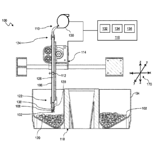
[0037] Fig. 1 is a cross-sectional view of a retrieval device. The device 100
may, in
general, include machinery and control software to enable the retrieval or
pickup of dispensable
units 102. As discussed herein, this may include blind retrieval in which
hardware performs a
predetermined sequence of moves according to a retrieval strategy without any
use of machine
vision or other similar techniques to locate and target an item for retrieval.
The blind retrieval of the
dispensable units 102 may follow a variety of particular retrieval patterns as
discussed herein. This
may for example include open loop retrieval strategies that execute as a fixed
sequence of retrieval
attempts without regard to sensor feedback or the like. This may also or
instead include closed loop
7
CA 02957272 2017-02-03
WO 2016/022714
PCT/US2015/043848
retrieval strategies where the patterns can be adapted "on the fly" using,
e.g., feedback, a machine
learning algorithm, and so on. Feedback data may include, e.g., detection of
contact with contents of
a container where a retrieval is being attempted, detection of whether a
retrieval attempt has been
successful, or any other type of feedback. A so-called blind retrieval
technique may use a variety of
non-optical feedback sources to evaluate and update various retrieval
strategies. The retrieval
patterns as described herein may thus enable the device 100 to have an
increased efficiency over
known machine vision systems of the prior art. For example, in
implementations, if the device 100 is
unsuccessful in a retrieval attempt, the chances of a successful retrieval can
improved on subsequent
attempts by intelligently adapting the retrieval pattern on a next attempt.
[0038] The device 100 may allow for the retrieval of dispensable units 102
having any size,
shape, color, texture, contour, weight, orientation, and so on. Additionally,
using feedback and
machine learning, the device 100 may learn improved parameters for retrieval
across different types
of dispensable units 102, or mixtures of dispensable units 102. Also, if the
dispensable units 102 are
of a known type or if they have known properties then the techniques described
herein can be used to
optimize the retrieval strategy accordingly. Similarly, information about
containers housing the
dispensable units 102 may be used to optimize retrieval. For example, the
cross-sectional shape of
the container through a horizontal plane of the container may help to
determine an effective pattern
for a series of blind retrieval attempts. Similarly, if the cross-sectional
shape of the container
changes along a z-axis, e.g., as retrievals are attempted deeper within the
container, then this may
affect retrieval strategics at each level, and at preceding levels.
[0039] The device 100 may include a container 104, a tube 106 with a nib 108,
a vacuum
device 110, a valve 112, a positioner 114, and a controller 116.
[0040] The container 104 may be any as described herein or otherwise known in
the art for
containing dispensable units 102 of the same type or of different types. The
container 104 may
include one or more contoured surfaces therein. The contoured surfaces may be
designed such that
dispensable units 102 are directed (e.g., by gravity or another force) to
certain areas/volumes within
the container 104, e.g., as the dispensable units 102 are being picked up by
the retrieval device 100.
For example, in one aspect, the bottom surface 120 of the container 104
includes contours having at
least one sloped portion. In this manner, as dispensable units 102 are
retrieved, units that remain in
the container 104 may be guided into a known location within the container 104
for retrieval e.g.,
in a vertically aligned container 104, the dispensable units 102 may be
funneled down into a known
8
CA 02957272 2017-02-03
WO 2016/022714 PCT/US2015/043848
location within the bottom of the container 104 through its contoured
surface(s) and the force of
gravity acting on the dispensable units 102. In other embodiments, another
force may work to
manipulate the dispensable units 102 within the container 104, e.g., a
centrifugal force, a force
caused by the nib 108 or other machinery, an agitation, a shaking or vibration
force, and so on.
100411 In one aspect, the container 104 is included on a carousel 118. The
carousel 118
may include a plurality of containers 104, where the carousel 118 is movable
for positioning at least
one of the plurality of containers 104 relative to another component of the
device 100, e.g., the nib
108, the tube 106, the positioner 114, and so on. For example, in an aspect,
the carousel 118 is
rotatable so that one of the plurality of containers 104 can be rotated into a
position for engagement
with the nib 108, which may itself have a limited range of motion within a
horizontal plane. The
carousel 118 may utilize the positioner 114 for its movement, or it may
include an independent
positioning mechanism. The positioning mechanism of the carousel 118 may
include
motors/actuators for automated movement or manual movement of the carousel 118
may be
provided by a user or operator. Where one or more containers 104 are arranged
around an axis of
rotation of a rotatable carousel 118, the positioner 114 may achieve coverage
of the entire projected
surface of the container 104 with a combination of radial movement by the nib
108 and rotational
movement by the carousel 118. Thus, in one aspect, general x-y positioning
within a horizontal plane
through one of the containers 104 can be affected through a combination of
radial and rotational
motion. In another aspect, the positioner 114 may provide x-y positioning
coverage throughout the
cross-section of a container 104, and the carousel 118 may be used to
rotationally select from among
a number of different available containers 104 on the carousel 118.
[0042] The tube 106 may have a first end 122 and a second end 124 coupled in
fluid
communication by a hollow core 126. The tube 106 may be flexible, rigid, or
any combination
thereof. The tube 106 may be made from one or more materials including without
limitation plastic,
rubber, metal, glass, ceramic, and so on. A flexible tube, e.g. made of
silicone or the like, could
confer space-saving advantages by folding (e.g., passive folding/unfolding or
active
folding/unfolding). The tube 106 may also or instead be food safe, e.g., to
meet the requirements of a
governing/regulating body (e.g., the Food and Drug Administration), using a
material such as
silicone or the like. The tube 106 may be bound flexibly, rigidly, or any
combination thereof, to any
wires or cables for operation of any electrical or electromechanical parts
associated with the device
100. The tube 106 (and/or the nib 108) may be capable of rotating, stretching,
compressing, or
9
CA 02957272 2017-02-03
WO 2016/022714 PCT/US2015/043848
otherwise deforming or transforming to engage dispensable units 102 from
different
angles/trajectories.
100431 The nib 108 may be disposed on the first end 122 of the tube 106. The
nib 108 may
include an opening 128 with a perimeter and a seal around the perimeter formed
of a pliable material
shaped and sized to engage and form a vacuum seal with an object having a
predetermined range of
dimensions, e.g., a dispensable unit 102. The nib 108 may include a bellows or
the like integrated
into the body of the nib 108 or the seal, which may compress and expand in a
manner that imposes a
predetermined range of contact forces around the perimeter of the nib 108 when
contacting an
object. In this manner, the contact force with a target object can be
normalized to improve the
vacuum seal provided around the perimeter. In one aspect, the bellows may
facilitate an adaptive
planar orientation of the opening 128 in order to more uniformly engage the
surface of target objects,
which may be in any arbitrary position and orientation within the container
104 where the nib 108 is
attempting a retrieval.
100441 Because the shape and size of the dispensable units 102 may vary (i.e.,
between the
same type of dispensable units 102 or between a mixture of different types of
dispensable units 102),
the predetermined range of dimensions may be a relatively wide range of
dimensions. For example,
in an aspect, the nib 108 can form a vacuum seal with small units such as less
than 5 mm, and larger
units such as greater than 150 mm. In an aspect, the shape and size of the
dispensable units 102
(including a range of shapes/sizes) is known a priori so that a suitably
shaped nib 108 can be
provided. In another aspect, the shape and size of the dispensable units 102
is unknown. In this
aspect, the shape and size of the dispensable units 102 may be dynamically
determined through
techniques discussed herein.
[0045] As stated above, the nib 108 may be formed of a pliable material,
including without
limitation, an elastomeric material such as rubber or silicone. Regardless of
material, in general, a
preferred embodiment of the nib 108 is flexible and/or compressible. The nib
108 may also or
instead include adhesive properties to permanently or temporarily bind to
dispensable units 102, as a
result of (and not limited to) one or more of the following features: pressure-
sensitive tape, suction
material, a suction cup, bellows, an adhesive coating, and so forth.
[0046] In an alternate embodiment, the device 100 does not include a nib 108,
but rather
the tube 106 retrieves the dispensable units 102 by drawing one of the
dispensable units 102 through
the body of the tube 106 with a vacuum force toward a desired destination.
CA 02957272 2017-02-03
WO 2016/022714 PCT/US2015/043848
[0047] The vacuum device 110 may include a vacuum source 130 connected in
fluid
communication with the second end 124 of the tube 106. The vacuum source 130
may include a
vacuum pump or the like, which provides a vacuum pressure in the hollow core
126 of the tube 106
such that the nib 108 at the first end 122 of the tube 106 can draw
dispensable units 102 in its
immediate environment for engagement via the force provide by a pressure
difference from inside
the tube 106 to outside the tube 106.
[0048] In an aspect, the vacuum device 110 is capable of reversing the
direction of air
flow, e.g., provided by the vacuum source 130. The direction of the air flow
may be reversed, for
instance, using a branching line with one or more solenoid valves or using a
reversible air pump.
Reversing the direction of air flow may allow for the removal of any
contaminants that are present
(e.g., attached to a filter or the like within the tube 106) in components of
the device 100, or
otherwise for the removal of objects obstructing air flow in non-reversed
operation of the device
100.
[0049] The valve 112 may be disposed between the nib 108 and the vacuum device
110,
where the valve 112 is operable to controllably apply a vacuum force from the
vacuum source 130
through the hollow core 126 to the nib 108. The valve 112 may provide for a
suction state when in a
first position and a releasing state when in a second position. In the first
position, the valve 112 may
be open, where the vacuum device 110 maintains a fluid connection with the
first end 122 of the
tube 106. In the second position, the valve 112 may be closed, where the valve
112 cuts off fluid
communication of the vacuum device 110 and the first end 122 of the tube 106.
Alternatively, the
valve 112 may otherwise provide for a break in the fluid connection between
the vacuum device 110
and the first end 122 of the tube 106, where a break in the fluid connection
equalizes pressure within
the tube 106 and its external environment. To assist with the pressure
equalization and thus the speed
with which the connection of a dispensable unit 102 is severed, the vacuum
device 110 may be
turned off at the same time as switching the valve 112 to its releasing state.
Such a valve 112 may be
controlled automatically, e.g., by a signal received from the controller, or
manually. In an aspect, the
valve 112 includes a solenoid valve or the like.
100501 The positioner 114 may be coupled to the tube 106 and configured to
move the nib
108 with at least two degrees of translational freedom within the container
104. In an aspect, the
positioner 114 is able to move the nib 108 with three degrees of translational
freedom within the
container 104, e.g., an x-axis and a y-axis for horizontal positioning within
the container 104, and a
11
CA 02957272 2017-02-03
WO 2016/022714 PCT/US2015/043848
z-axis for lowering into the container 104 to attempt a retrieval at a
particular x-y location. In
another aspect, the positioner 114 may provide two degrees of translational
freedom, e.g., an x-axis
and the z-axis, while rotation of the carousel 118 provides a third degree of
freedom for arbitrary
positioning of the nib 108 relative to the container 104. Other arrangements
may also or instead be
used. For example, the carousel 118 may be vertically movable to provide a
translational degree of
freedom along the z-axis, or the positioner 114 may be movable radially and
rotationally on an arm
extending from an axis of the carousel 118. More generally, any arrangement of
positioning
mechanisms suitable for arbitrarily positioning the nib 108 within the
coordinate system of the
container 104 may be suitably employed as the positioner 114 and/or carousel
118 as contemplated
herein.
[0051] The positioner 114 may include mechanical elements such as one or more
actuators
(e.g., linear actuators, pneumatic actuators, and so on) powered by one or
more motors (e.g., stepper
motors, servomotors, brushed/brushless DC motors, and so on). The positioner
114 may also or
instead include any sub-mechanisms for providing movement, such as belts,
pulleys, gears, threaded
rods, rack and pinion systems, rails, guides, brakes, and so forth.
[0052] The positioner 114 may position one or more of the tube 106, the nib
108, the
container 104, or another component of the device 100. The positioner 114 may
provide for a full
range of motion of the component to which it is engaged, or for limited
movement, e.g., movement
along one or more axes. In an aspect, the entire tube 106 is movable by the
positioner 114.
Additionally or alternatively, certain portions of the tube 106 may be
positionablc by the positioner
114 or otherwise. For example, portions of the tube 106 may be positionable by
bending the tube
106 (e.g., in an embodiment where the tube 106 is flexible) or hinging the
tube 106 (e.g., in an
embodiment where the tube 106 is rigid). Thus, the tube 106 may include
hinges, articulating joints,
and the like for positioning in an embodiment. The hinges may be configured to
allow the tube 106
to remain airtight, and/or to prevent kinking or closing of the tube 106.
Hinging the tube 106 in this
manner may be advantageous because the tube 106 can maintain suction while
bending. Hinging or
flexing of the tube 106 in such a manner may change a rotational orientation
of the tube 106 or nib
108.
[0053] In an aspect, the positioner 114 or another component of the device 100
provides
rotational movement of the tube 106. This may include a radial positioning
system.
12
CA 02957272 2017-02-03
WO 2016/022714 PCT/US2015/043848
[0054] The positioner 114 or another component of the device 100 may provide
for a
stabilized and smooth motion of the device 100. This may be done mechanically,
e.g., using bearings
such as ball bearings, bearing wheels, and the like, and/or through the use of
software, including but
not limited to feedback controlled actuators. The positioner 114 or another
component of the device
100 may also or instead allow a small or moderate amount of freedom or
"wobble" in its motion,
particularly in the retraction motion when retrieving a disposable unit 102.
In this manner, one or
more parts of the tube 106 may move freely in the horizontal plane while
travelling vertically (or
vice-versa). Such an embodiment may be advantageous because it can introduce
noise and
randomness to the position of the nib 108 during pickup of a disposable unit
102, thereby allowing
new configurations of the nib 108 that can be more successful at pickup.
Furthermore, such freedom
may enable the first end 122 of the tube 106 to better conform to the surface
of the disposable unit
mixture and the surface of an individual disposable unit 102 as the first end
122 of the tube 106
moves toward this surface or unit, thus forming a tighter coupling and/or
stronger seal.
100551 In an aspect, movement of the mixture of disposable units 102 relative
to the tube
106 is accomplished through movement of the container 104.
[0056] Actuating the tube 106, via the positioner 114 or otherwise, may add a
significant
bulk, height, or width to the device 100, regardless of whether the tube 106
is flexible or rigid. To
reduce the dimensions, the device 100 or tube 106 may have one or more of the
following sub-
mechanisms: the tube 106 may be flexible within a scissor lift that compresses
and extends for
plunging; the tube 106 may be rigid but telescoping, where it extends for
plunging; the device 100
may include a flexible rack attached to a flexible tube, where these
components bend when in
retracted positions (e.g., a flexible rack and pinion design); a chain may be
attached to a flexible
tube, where these components bend in in retracted positions; and so forth. The
sub-mechanisms may
allow for collapsing/extension in any spatial dimension or orientation,
including but not limited to
vertical, horizontal, and around a substantially radial or circular path. The
sub-mechanisms may
dynamically change the path of their collapsing/extension depending on the
environment and/or
enclosure. For any telescoping embodiments or the like, different sections may
be included that are
relatively tightly connected concentric portions. The sub-mechanisms, or
components or sections
thereof, may also or instead be coated with a sealant or lubricant, i.e., in
an effort to preserve an
airtight seal.
13
CA 02957272 2017-02-03
WO 2016/022714 PCT/US2015/043848
[0057] The positioner 114, or other components of the device 100, may be
powered by
alternating current (AC) power (e.g., from a grid) or direct current (DC)
power (e.g., from a battery).
The device 100 may have a battery backup to run the device 100 in the event of
a power outage or
unreliable/inconsistent power scenario. The battery may also or instead
restore the device 100 to a
safe or a manually overridcable state for reasons related to safety. The
battery may be connected to
the device 100 via a diode so that power is only drawn from the battery if a
main power line voltage
drops below a predetermined threshold, e.g., that of the battery (e.g., in the
case where it is a lower
voltage relative to a main power line).
[0058] The controller 116 may be coupled in a communicating relationship with
one or
more mechanical components of the device 100, e.g., the vacuum device 110, the
valve 112, and the
positioner 114. The controller 116 may be configured to operate the nib 108 to
attempt a blind
retrieval of a number of dispensable units 102 within the container 104 using
a sequence of retrieval
attempts each applying a different two-dimensional retrieval pattern within a
first horizontal plane
through the container 104. The controller 116 may also provide for the device
100 to attempt other
retrieval patterns, e.g., a one-dimensional retrieval pattern and a three-
dimensional retrieval pattern.
[0059] The controller 116 may include any hardware or software to provide
programming
as described herein. Those skilled in the art will recognize that a variety of
different controllers 116
may be used in the implementations described herein. The controller 116 may be
programmable and
include a network interface 132, a processor 134, a memory 136, and any other
hardware or software
to perform its functions as described herein.
[0060] The two-dimensional retrieval pattern used for the retrieval attempts
taken by the
device 100 may be determined by the controller 116, the processor 134, or
another component of the
device 100 (or a component in communication with the device 100, e.g., a
remote device or server
connected through the network interface 132). In an aspect, the two-
dimensional retrieval pattern is
determined based on feedback, e.g., information related to a previous
retrieval attempt. This
information may include without limitation whether the retrieval attempt was
successful or
unsuccessful, the position of the nib 108 at any point in the retrieval
attempt (e.g., the position within
the first horizontal plane, a z-axis position, an x-y-z coordinate, and so
on), a weight of the
dispensable unit 102 retrieved, a size of the dispensable unit 102 retrieved,
a force exerted on the nib
108 or other component of the device 100, a location relative to the container
104 or a location
within the container 104, and so forth.
14
CA 02957272 2017-02-03
WO 2016/022714 PCT/US2015/043848
[0061] The two-dimensional retrieval pattern used for the retrieval attempts
taken by the
device 100 may also or instead include offsetting a position of the nib 108
within the first horizontal
plane by a distance greater than half of a cross-sectional width of the nib
108. The offsetting of the
position of the nib 108 may first include retracting the nib 108 relative to
the contents of the
container 104, and then offsetting the nib 108 by a distance greater than half
of a cross-sectional
width of the nib 108 away from the previous retrieval attempt. In this manner,
the nib 108 may be
disposed in a location adjacent to its previous retrieval attempt by a
distance configured to achieve a
different result and/or place the nib 108 away from the epicenter of a hole
created by a previous
retrieval attempt. In other words, horizontally moving the nib 108 less than
this distance may place
the nib 108 within a hole or the like created by a previous plunge. The
offsetting may also or instead
include an agitating motion, i.e., moving the nib 108 a distance in the first
horizontal plane to
displace dispensable units 102 when the nib 108 is plunged into the container
104. Thus, agitation
can be facilitated with small horizontal movements of the nib 108 (such as a
half width of the nib
108 or tube 106) while inserted into the container 104.
[0062] The position of the nib 108 for an attempted retrieval within the first
horizontal
plane may be selected based on a variety of factors. This process of selecting
positons may be
parameterized along any number of different dimensions. For example, a target
positon of the nib
108 in the first horizontal plane for a retrieval attempt may be selected by
the controller 116 based
on the number of retrieval attempts in a two-dimensional retrieval pattern
(e.g., at a particular height
or otherwise). In general, the larger the number of retrieval attempts that
are to be made within a
particular horizontal plane, the more closely spaced each attempt will be to
other attempts. The
pattern or strategy may be determined according to this and any number of
additional parameters for,
e.g., separation distance between sequential retrieval attempts, time between
sequential retrieval
attempts, a speed of axial movement of the nib 108 (e.g., upwards or
downwards), a trajectory of
movement of the nib 108, a retreat margin of the nib 108, a speed of
retreating of the nib 108 (e.g.,
above the retreat margin as described herein), a speed of approaching
dispensable units 102 from a
predetermined distance, an acceleration (or deceleration) while positioning
the nib 108 (e.g.,
vertically or horizontally), a speed of horizontal movement of the nib 108,
power (or a related
property thereof, e.g., current) supplied to the positioner 114, power
supplied to the vacuum device
110 or another component of the device 100, a pulse width modulation (PWM)
frequency and duty
cycle for a powered component, a property or state of the valve 112 (e.g., the
length of time the
CA 02957272 2017-02-03
WO 2016/022714 PCT/US2015/043848
valve 112 is in a released state or time the tube 106 is in an equalized or
equalizing pressure state), a
rigidity of the tube 106, a gear ratio of the positioner 114 (e.g., of
actuators or motors contained
therein), a shape of the tube 106 or a component thereof (e.g., a shape of the
nib 108, which as
discussed herein may be compressible), a retrieval angle of the nib 108 (e.g.,
a plunge angle relative
to a vertical or z-axis), the size of objects for retrieval, the weight of
objects for retrieval, the shape
of objects for retrieval, the surface texture of objects for retrieval, the
dimensions of the container
104 in which retrieval is being attempted, the shape of the container 104,
supplemental capabilities
of the container 104 (e.g., self-agitation to level a top surface of the
objects, a stirrer to mix/level
objects, ability to rotate or move within the horizontal plane, z-axis depth,
etc.), and so on. Any of
the above may also or instead be used as dimensions or parameters for
individual retrieval attempts
or patterns of retrieval attempts within a particular plane or from plane to
plane. Spatial patterns may
also be indexed and selected for use with a pattern parameter. For example,
there may be general
patterns such as parallel lines, spirals, concentric circles or other shapes,
crisscrosses, random
patterns, and so forth, any of which may be specified by a suitable parameter
and then adapted to the
shape of a container 104. Any of the above aspects of a retrieval strategy may
be represented as
inputs to the system, i.e., parameters that may be modified by the system for
controlling the two-
dimensional retrieval pattern. Specifically, these inputs may be modified to
optimize the system
based on the outputs described below.
[0063] The two-dimensional retrieval pattern dimensions may also or instead be
determined based on, e.g., one or more of the following environmental
constraints: a horizontal area
covered by the dispensable unit mixture, a three-dimensional shape of the
container 104 in which the
dispensable unit mixture is contained, a varying height of the surface of the
dispensable unit mixture
(e.g., if not flat), and so forth. The environmental constraints may be
constant, or they may change
over time, e.g., as dispensable units 102 are retrieved.
[0064] The two-dimensional retrieval pattern used for the retrieval attempts
taken by the
device 100 may also or instead be determined based on one or more of: a rate
of successful retrieval
of dispensable units 102, a time to retrieve one dispensable unit 102, a time
to retrieve a
predetermined number of dispensable units 102, a noise level (measured for
instance by a
microphone or a human), a rate of unsuccessful retrievals, a vibration
(measured for instance by a
gyroscope), manual user feedback (e.g., according to user preferences), a
pattern category (e.g., a
random step pattern versus a pattern with a determined order of step
locations), and so forth. The
16
CA 02957272 2017-02-03
WO 2016/022714 PCT/US2015/043848
foregoing may represent outputs to the system, which can be measured and
optimized by varying the
aforementioned inputs referenced above. For example, if the rate of successful
retrieval of
dispensable units is low (e.g., the measured output is much less than an
optimal value), one or more
of the inputs may be adjusted in an attempt to raise this value, e.g., a
separation distance between
retrieval attempts may be increased or decreased.
[0065] The determination of pattern dimensions may occur via one or more of
several
methods, including but not limited to: a manual trial-and-error of different
patterns, a pre-defined,
automatic "testing phase," a predetermined sequence of patterns or steps in a
pattern, a machine
learning process, a machine vision process, using randomization or random
values, and so forth.
[0066] In an aspect, if the pattern is determined using a "testing phase," the
device 100 can
have a set of generic patterns preloaded into digital memory (e.g., in the
memory 136 of the
controller), where each of the patterns is tested and the resulting metrics
after each is observed.
Then, a pattern may be selected for a particular unit mixture if it optimizes
the pre-defined metrics.
100671 In an aspect, if the pattern is determined using a machine learning
process, the
device 100 may start with a default starting pattern, and iteratively
construct a pattern with globally
(or near-globally) optimal pattern dimensions (e.g., through one or more of
the illustrative pattern
dimension factors provided above) to optimize the pre-defined metrics, e.g.,
using one or multiple
optimization algorithms and techniques (including but not limited to a simplex
algorithm, Newton's
method, finite difference, gradient descent/hill climbing, and simulated
annealing). The device 100
may separately use (independently or in conjunction) one or more supervised or
unsupervised
learning algorithms, such as nearest neighbor, neural networks, and cluster
analysis. An illustrative
example of the learning process may have the following steps: (1) begin at a
pre-determined default
pattern (with default dimensions) for instance using a winding route or a
spiral route, (2) run one or
many steps of the pattern, (3) measure the pre-defined metrics m, (4) modify
one of the dimensions
d (e.g., a number of steps) by a small increment ad that is expected to
improve the measured metric
mi, based on the change in mi during the previous step, (5) repeat steps 2-4,
choosing a new small
increment, (6) repeat steps 2-5 until this dimension is optimized within a
predefined or
algorithmically determined margin of error j for that dimension, (7) move to
another dimension,
and optimize via steps 2-6, holding the other dimension constant, (8) repeat
steps 2-7 until
optimized in all dimensions. In an aspect, ad can be a small fraction, e.g.,
approximately one percent
of the total range of values that a dimension may take, for instance:
(new_plunge_speed) =
17
CA 02957272 2017-02-03
WO 2016/022714 PCT/US2015/043848
(old_plunge_speed + (max_plunge_speed x 0.01)). This fraction may be
empirically determined for
optimality.
1006811 In an aspect, if the pattern is determined using a machine vision
process, the device
100 may have one or more optical sensors or cameras (e.g., charge-coupled
device (CCD),
complementary metal-oxide-semiconductor (CMOS), and the like) on a top surface
(or -ceiling"
surface) or at the bottom of the tube 106, i.e., facing downward towards the
dispensable unit
mixture. Based on images generated by these sensors, a microprocessor (e.g.,
the processor 134 of
the controller 116) may perform image recognition to determine where visible
dispensable units 102
are located (e.g., by using edge detection algorithms), and direct the
horizontal actuation such that
the tube 106 is plunged vertically down to a center of a dispensable unit 102
that appears to have a
high success rate for retrieval, which in most operations is the dispensable
unit 102 that has the
largest surface area exposed to the optical sensors. Furthermore, in an aspect
with actuators disposed
near the bottom of the tube 106, the microprocessor may also or instead direct
the actuators to bend,
hinge, or otherwise direct the bottom of the tube 106 towards the center of
the dispensable unit 102
that appears to have a high success rate for retrieval, and which is also in
range of the tube's bending
or hinging. Additionally, when using the machine vision process in conjunction
with the machine
learning process, the image recognition may be used to determine the average
dispensable unit 102
shape, size, and separation, hence informing the optimal separation between
"plunges" (i.e., one of
the pattern dimensions discussed above).
100691 The device 100 may receive input from an external signal or message,
indicating,
for example, the following or a combination of the following: the exact
pattern (i.e., pattern
dimensions) to use, the default starting pattern as a beginning for the
machine learning process
discussed above, and the size of the small increment od for a particular
pattern dimension in the
machine learning process. This input may be driven by a detection received
from some other
component related to an environmental constraint, including but not limited
to: the average size,
shape, texture, weight, and orientation of dispensable units 102 in one or
more of the nearby
mixtures, the ambient temperature, pressure, or humidity, and the like, or
other factors or inputs.
This input may come from a human or a machine, where examples of the latter
include but are not
limited to a server (via the internet/intranet, Ethernet, ZigBee, WiFi, 3G,
4G, LTE, WiMAX, and so
forth), another processor (whether onboard the device 100 or not), a remote
resource, and so forth.
18
CA 02957272 2017-02-03
WO 2016/022714 PCT/US2015/043848
100701 Although the device 100 in the figure is shown as a vertically-aligned
retrieval
device, where the two-dimensional retrieval pattern is discussed as being
through a horizontal plane,
one skilled in the art will recognize that other alignments are also or
instead possible. For example,
in another aspect, the device is a horizontally-aligned retrieval device,
where the two-dimensional
retrieval pattern is through a vertical plane. Other alignments, e.g., tilted
or angled alignments are
also possible. Still more generally, while an x, y, z coordinate system 170
generally serves as a
convenient basis for positioning within three dimensions and are included in
some of the discussions
regarding positioning herein, any other coordinate system or combination of
coordinate systems may
also or instead be employed, such as a positional controller and assembly that
operates according to
cylindrical or spherical coordinates.
[0071] Actuation and movement of components of the device 100 along any axes
or any
directions may be controlled or restrained by various sensing systems (which
may be collectively
referred to herein as "actuation sensor systems") and mechanical constructs.
Such actuation sensor
systems may include but are not limited to optical-interrupter-based encoders,
rotary encoders, linear
encoders, quadrature encoders, and the like. The actuation sensor systems may
include the resolution
of encoding for preferred, accurate motion, along with one or more index or
"home" positions. Such
actuation sensor systems may be used in conjunction with control software to
drive the actuation,
e.g., of motors included in the positioner 114. Mechanical constructs may
include hard stops (e.g., a
protruding lip) and the like. Actuation may use a combination of actuation
sensor systems and
mechanical constructs.
100721 As discussed herein, motion may be relatively smooth to ensure
relatively fast
retrieval of dispensable units 102, a relatively high rate of retrieval
success, and a durable
mechanism. This may be achieved by using ball bearings, ball bearing wheels,
smooth metal rods
(e.g., stainless steel SS301, SS303 or SS304 with 9 micron finish or finer),
Kapton tape, or similar.
Some embodiments may have less smooth travel on one or more axes relative to
another, e.g., for
dampening motion.
[0073] The device 100 may further include an agitator 138 engaged with the
first end 122
of the tube 106 that converts an axial force created by a vertical movement
(i.e., plunging) of the
tube 106 or plunger into a horizontal force parallel to (or substantially
parallel to) the first horizontal
plane for agitation of the dispensable units 102. In other words, when the
tube 106 is plunged in a
direction along the z-axis, the agitator 138 may displace dispensable units
102 in which it contacts
19
CA 02957272 2017-02-03
WO 2016/022714 PCT/US2015/043848
along one or more of the x-axis and the y-axis, e.g., through an x-y plane.
The agitator 138 is further
described below.
[0074] In general, in use, the device 100 may involve the tube 106 with the
nib 108 being
plunged (e.g., vertically or substantially vertically, horizontally or
substantially horizontally, or
otherwise) into a mixture of disposable units 102. This actuation may occur
using the positioncr 114
as described herein. Upon contact between the nib 108 and a disposable unit
102 (e.g., on the surface
of the mixture or near the surface of the mixture), suction caused by the
pressure difference between
tube 106 and the external environment may draw the disposable unit 102 to the
nib 108, where the
nib 108 forms a sealed connection with the disposable unit 102. The disposable
unit 102 may thus be
held by the tube 106 due to the force of the vacuum pressure, which is
selected to be sufficiently
strong to keep the disposable unit 102 connected to the nib 106 against the
force of the weight of the
disposable unit 102 and any disturbing or resistive forces such as that
imposed by other disposable
units 102 nearby, heavy vibrations, movement of the nib 108 or tube 106, or
otherwise.
100751 Once the connection with the disposable unit 102 has been made, the
positioner 114
may retract the tube 106 from the container 104, e.g., pull the tube 106 up
along the z-axis in the
vertically-aligned device shown in the figure. Due to the engagement, the
disposable unit 102 may
travel with the tube 106. Upon a signal, e.g., from the controller 116, the
engagement may be
broken, thus releasing the disposable unit 102, which may fall due to, e.g.,
its own weight, an
artificially applied field (e.g., magnetic field), or similar. The engagement
between the nib 108 and
the disposable unit 102 may be broken, e.g., by turning off the vacuum source
130, by releasing a
mechanical grabber, by operation of the valve 112, and the like.
[0076] Fig. 2 is a cross-sectional view of a retrieval arm. The retrieval arm
200 may be part
of a retrieval device as described herein, and may include a tube 206 having a
first end 222 and a
second end 224, a nib 208, a hollow core 226, an opening 228, and an agitator
238. The retrieval arm
200 may otherwise be referred to herein as a plunger.
[0077] As shown in the figure, the agitator 238 may include one or more angled
surfaces
240, or otherwise sloped or contoured surfaces. The angled surface 240 may be
configured to
displace dispensable units when the nib 208 attempts the blind retrieval as
described herein.
Specifically, when the retrieval arm 200 is plunged into a container of
dispensable units, the angled
surfaces 240 may engage with one or more of the dispensable units thereby
displacing them, e.g.,
horizontally away from the retrieval aini 200 when the retrieval arm 200
plunges vertically. In this
CA 02957272 2017-02-03
WO 2016/022714 PCT/US2015/043848
manner, the agitator 238 may convert an axial force created by a plunging of
the tube 206 into a
horizontal force within a horizontal plane (e.g., the first horizontal plane
described herein) for
agitation of the dispensable units.
100781 In an aspect, the agitator 238 substantially resembles a cone or a
truncated cone,
which can aid in preventing damage to dispensable units by directing the units
radially outward from
the retrieval arm 200 when it plunges downwards.
[0079] As shown in the figure, the nib 208 may include one or more bellows
242. The
bellows 242 may be formed by a substantially pleated layer of material
included on the nib 208 that
penults the nib 208 to be compressible. Being compressible may allow the nib
208 to conform its
shape to the shape or texture of a dispensable unit, while also or instead
permitting the nib 208 to
absorb axial forces caused by a plunging of the tube 206. At the same time,
the bellows 242 can
facilitate reorientation of the seal 243 around the perimeter 244 of the
opening 228 so that the plane
of the seal 243 can adjust to a range of arbitrary planar orientations of the
surface of objects within
the container. In this manner, the nib 208 can maintain a predetermined range
of contact forces
around the perimeter 244 to form a desired vacuum seal when contacting objects
in a range of
different positions and orientations within the container. The bellows 242 may
be formed of the
same material that forms the nib 208 or a majority thereof, or the bellows 242
may be formed of a
different material. In an embodiment, one or more of the nib 208 and bellows
242 may be formed of
an elastomer, such as silicone rubber or the like, although other materials
are also or instead
possible. The bellows 242 may permit the seal 243 of the nib 208 to move
relative to the tube 206 as
the positioner moves the tube 206 vertically into the container, thereby
maintaining a predetermined
range of contact forces as the seal 243 of the perimeter 244 of the nib 208
contacts contents of the
container. This can allow the nib 208 to absorb axial forces created through
contact of the nib 208
with contents of the container or other objects/components. The bellows 242
may be further
configured to normalize an axial force on the nib 208 created by a plunging of
the tube 206 in order
to strengthen the vacuum seal between the nib 208 and a dispensable unit.
00801 The retrieval arm 200 may further include a biasing element 252 that
works in
conjunction with an indicating element 250. The biasing element 252 may
movably couple the
indicating element 250 to the tube 206, where the biasing element 252 biases
the indicating element
250 in a direction with a predetermined biasing force. For example, in a
vertically aligned retrieval
device, the biasing element 252 may bias the indicating element 250 in an
axial direction (along a z-
21
CA 02957272 2017-02-03
WO 2016/022714 PCT/US2015/043848
axis), i.e., perpendicular to a surface formed by contents of a container. The
predetermined biasing
force may be selected such that a force on the tube 206 that causes
compression of the biasing
element 252 does not damage one or more of the tube 206 and the dispensable
units. In an aspect,
the indicating element 250 is engaged with the nib 208 such that the
indicating element 250 moves
relative to the tube 206 when a contact force applied to the nib 208 is
greater than the predetermined
biasing force on the indicating element 250. In one aspect, the nib 208 and
the indicating element
250 may be configured such that any vertical movement of the nib 208 relative
to the tube 206 also
causes vertical movement of the indicating element 250. In another aspect, the
nib 208 and the
indicating element 250 may be configured such that the nib 208 can compress a
predetermined
amount before the indicating element 250 will move relative to the tube 206.
This compression may
be made possible by the material of the nib 208 as described herein. The
retrieval device or system
may further include a controller as described herein, where the controller is
configured to infer
contact of the nib 208 with contents of the container upon detecting a
movement of the indicating
element 250 relative to the tube 206. This inferred contact may indicate to
the retrieval device or
system that the nib 208 has contacted a surface formed by the contents of a
container, thereby
providing an axial position of this surface to the controller or other
component of the retrieval device
or system.
100811 As shown in the figure, the indicating element 250 may be disposed on
the first end
222 of the tube 206. The biasing element 252 may include a mechanical spring
or the like, and/or the
biasing element 252 may include an elastomeric material, e.g., of the
indicating element 250 or
another component of the retrieval arm 200 such as the nib 208. The biasing
element 252 may utilize
a mechanical stop 254 provided on the retrieval arm 200 (e.g., on the tube
206), which can
counteract a contact force on the indicating element 250 or nib 208. As
discussed above, a
predetermined force that allows for compression of the biasing element 252 may
be selected to
coincide with a force exerted on the tube 206 when the first end 222 of the
tube 206 contacts a
plurality of dispensable units, e.g., dispensable units that form a top
surface of a dispensable unit
mixture in the container.
100821 In an embodiment, the indicating element is the nib itself. In this
embodiment, the
biasing element may be the pliable material of the nib that allows the nib to
be compressible, or the
biasing element may be a separate component that movably couples the nib and
the tube. In another
embodiment, the indicating element 250 is coupled to the nib 208 (as shown in
the figure). In yet
22
CA 02957272 2017-02-03
WO 2016/022714 PCT/US2015/043848
another embodiment, the indicating element and the agitator are the same
component, where the
agitator is movable in an axial direction on the tube.
[0083] In an implementation in which the indicating element 250 is connected
to the nib
208, the indicating element 250 may be minimally separated from the nib 208.
In an aspect, the
indicating element 250 is seamlessly connected to the nib 208 or is otherwise
a part of the nib 208.
For example, the indicating element 250 may be molded onto the nib 208. Such a
connection can
ensure that there is no room for contaminants or residue to travel up between
the nib 208 and the
indicating element 250 and therefore damage or interfere with mechanics or
electronic functionality.
[0084] In an aspect, the biasing element 252 may also serve to absorb a force
caused by
contact between the first end 222 of the tube 206 (which may or may not have a
nib 208) and a
surface of the dispensable unit mixture (or a surface of the container or the
like). The biasing
element 252 may thus prevent the tube 206 from transferring a relatively
strong force to the
dispensable unit mixture (or vice-versa), which may prevent damage to one or
more of the
dispensable units or the tube 206.
[0085] The retrieval arm 200, or another component of the retrieval device or
system, may
include a filter 260. The filter 260 may prevent contaminants from entering
the vacuum device
through the tube 206. The filter may use active or passive filtration to
remove contaminants, and
may be powered or unpowered in the active filtration embodiment. A passive
filter may include a
filtration material (e.g., a porous cloth or plastic) and an enclosure around
the filtration material to
create a seal in the line in which it is disposed and ensure that air flows
through the filtration
material. The filtration material may be shaped in several ways, including but
not limited to a disc, a
cone, a cylinder, and so on.
[0086] The filter 260 may be located within the tube 206 or along another
portion of the
retrieval device or system. Wherever disposed, the volumes adjacent to the
filter 260 may be shaped
such that there is a certain predetermined volume preceding the filter 260 and
a certain
predetermined volume following the filter 260 (e.g., relative to the direction
of flow of air in an
embodiment including a vacuum device). The volume following the filter 260 may
be relatively
small, e.g., to ensure that there is as little recirculation of air flow as
possible (which can lead to
energy loss). The volume preceding the filter 260 may also or instead be
relatively small to prevent
similar recirculation, but it may be large enough such that any contaminants
blocked by the filter 260
have space to fall or be pulled by a different force away from the filter 260,
thus preventing air flow
23
CA 02957272 2017-02-03
WO 2016/022714 PCT/US2015/043848
through the filter 260 from being blocked. The preceding predetermined volume
may further include
a trough section, situated in the direction of such a "different force" (which
may be gravity, thus the
trough may be situated under the filter 260 with respect to gravity), which
would be disposed in a
region in which contaminants could collect without substantially obstructing
an air flow.
[0087] Fig. 3 is a cross-sectional view of a retrieval arm. The retrieval arm
300 may be an
alternate embodiment of the retrieval arm discussed above. In this embodiment,
the indicating
element 350 may work in conjunction with a sensor 356 and guide rails 358.
[0088] In one aspect, the sensor 356 is configured to detect movement of the
indicating
element 350 relative to the tube 306 and to send a signal to a controller when
the movement is
detected. Upon receiving the signal that movement of the indicating element
350 relative to the tube
306 is detected, the controller may be configured to halt or reverse axial
movement of the nib 308
within the container. This may prevent damage to one or more of the
dispensable units and the tube
306 by terminating a downward motion of the tube 306 and nib 308 upon contact
with objects within
a container, or more specifically, when the contact force between the nib 308
and the objects exceeds
a predetermined threshold governed by a spring constant or the like of the
biasing element 352.
[0089] The sensor 356 may include an optical-interrupter sensor or the like.
For example,
upon compression of the biasing element 352, a light-blocking and/or
reflective protrusion or the
like may move into a path of the optical-interrupter sensor, thus triggering a
signal that the first end
322 of the tube 306 has touched the surface of the dispensable unit mixture.
This protrusion may be
made of metal (e.g., stainless steel) for optimal interrupting in the
environment within the retrieval
device, where such an environment can include air, dust, residue, and other
materials or
contaminants that might be present in the gap between an optical-interrupter.
[0090] In another aspect, the sensor 356 includes electrical contacts that are
separated at
rest, e.g., in the absence of external forces, and that come into contact with
one another upon
compression of the biasing element 352. Such contact may complete a circuit,
thereby transmitting
an analog or digital signal to a controller, which would thus determine that
the first end 322 of the
tube 306 has touched the surface of the dispensable unit mixture (with a
predetermined contact force
sufficient to overcome the biasing force of the biasing element 352). In such
an embodiment, the
first end 322 of the tube 306 may be electrically insulated to prevent a
completion of the circuit
when at rest (i.e., when the biasing element 352 is not compressed), thus
preventing transmission of
an incorrect signal. The biasing element 352 and contacts may also or instead
reside entirely within a
24
CA 02957272 2017-02-03
WO 2016/022714 PCT/US2015/043848
mechanical switch or the like. Numerous other contact sensors and systems are
known in the art, and
may be adapted for use with the retrieval arm 300 contemplated herein.
[0091] Information provided by the indicating element 350 or another component
of the
retrieval arm 300 or retrieval system may be stored, e.g., in a memory or
database that is coupled in
a communicating relationship with the controller (or disposed in the
controller itself). In an aspect,
the memory may store a position of the nib 308 (e.g., an axial position) where
movement of the
indicating element 350 relative to the tube 306 is detected. This may be a z-
axis or vertical axial
position that corresponds to a top surface of the plurality of dispensable
units within the container.
This may also or instead include a horizontal or x-y position at which the
contact was detected. The
controller may then be configured to position the nib 308 for a retrieval
attempt in the two-
dimensional retrieval pattern at a predetermined height. The predetermined
height may be disposed
above the surface of the plurality of dispensable units within the container
such that the nib 308 will
not contact the dispensable units until making a retrieval attempt and will
thereby not be hindered by
the dispensable units. The predetermined height may also be disposed
relatively close to the surface
of the plurality of dispensable units, such that the time when retracting the
nib 308 (e.g., after an
unsuccessful retrieval attempt) is reduced.
[0092] Thus, in an aspect, in order to compensate for a vertically uneven
disposable unit
mixture, the system may store, record, extrapolate, or otherwise capture or
calculate the depth or
"level" at which it previously encountered a dispensable unit, which may be
equivalent to the surface
level of the mixture at that horizontal coordinate. This information may be
advantageously employed
in a number of ways when determining a retrieval pattern or strategy. For
example, this information
may be used to prevent horizontal movement of the nib 308 into dispensable
units that might damage
the retrieval arm 300. This may also be used to avoid damaging dispensable
units through excessive
vertical motion or dragging across a top surface of the units within a
container. In another aspect,
this information may be used to select a specific z-axis position where a next
retrieval will be
attempted, either within the neighborhood of the contact detection or at other
locations within the
container. Thus, the system may record a surface level at several horizontal
coordinates, and may use
this information to map or estimate the surface level throughout the
container. With such
information, the mechanism could retreat to a safe vertical position that is a
certain distance (i.e., a
"retreat margin") above the surface of the dispensable units at the next
pattern location, and could
thus move to that new elevated position without striking dispensable units
horizontally. Furthermore,
CA 02957272 2017-02-03
WO 2016/022714 PCT/US2015/043848
to increase the speed of the entire process, the retrieval arm 300 may
establish a separation margin¨
a minimum distance between the nib 308 and the expected surface height¨as a
rule to be followed
before horizontal movements. Thus, the amount of z-axis movement may be
reduced or eliminated
to save time during and between retrieval attempts.
[0093] The sensor 356 may also or instead work in conjunction with, or be
replaced by,
other sensors or distance-controlled motors, including but not limited to,
Hall effect sensors, rotary
encoders, linear encoders, linear actuators, stepper motors, and so on. In
this manner, the retrieval
mechanism may be used to inform the controller of the depth distance of the
surface of the
dispensable unit mixture at the tube's current horizontal coordinates,
depending on the distance
travelled before the sensor 356 (or otherwise) was activated.
[0094] Further examples of other sensors that may be utilized include without
limitation
optical sensors (e.g., for computer-aided counting of surface and sub-surface
dispensable units),
motion sensors (e.g., for accurate depth readings), porosity sensors, acoustic
resonator/sensors (e.g.,
for depth and volume readings), humidity sensors, temperature sensors, and so
on. Adaptations of
these embodiments may place described sensors anywhere within the described
device or system, for
instance within the containers.
[0095] The guide rails 358 may provide for movement of the indicating element
350 or a
component thereof, e.g., in the axial direction. The guide rails 358 may also
or instead prevent
unwanted movement of the indicating element 350 or a component thereof, e.g.,
in the horizontal
direction.
[0096] The retrieval arm 300 may also include a cover 362 that protects
components
disposed therein. These components may include, e.g., the sensor 356, the
biasing element (e.g., a
spring), the guide rails 358, and so forth. The cover 362 may be particularly
advantageous to prevent
build-up of material from the dispensable unit mixture on an optical-
interrupter sensor or the like.
[0097] Any of the devices and systems described above may also include other
advantageous control features, e.g., provided by a processor within a
controller or the like. For
example, a processor may estimate the number of dispensable units remaining in
a container, for
example using calculations based on one or more of: (1) a vertical location of
the surface of the
dispensable unit mixture at one or more horizontal coordinates, (2) a depth of
the dispensable unit
mixture at one or more horizontal coordinates along the surface of the
dispensable unit mixture, (3)
the depth of the container at the horizontal coordinates where there are no
dispensable units in the
26
CA 02957272 2017-02-03
WO 2016/022714 PCT/US2015/043848
container (this may be a known property of the container), and (4) dispensable
unit characteristics
(e.g., based on the pattern dimensions determined as described herein), which
can allow for the
calculation of average density of the dispensable units.
[0098] All information, data, calculations and measurements contemplated
herein
(including but not limited to machine learning data and sensor data) may be
stored in a database,
displayed to a user, transmitted locally (e.g., to other integrated circuits)
or remotely (e.g., to a
server), or further processed. All data, for instance machine learned pattern
dimensions, may have
local values (i.e., within the mechanism) and global values (e.g., at a
remote, central location, such
as a server). The global values may be communicated to multiple devices or
systems that may or
may not be in proximity, and then such mechanisms can combine their existing
local values with the
received global values to calculate a new blended set of local values that
could be used for
processing or storage in a database, communication to a user, or any other
data use described herein.
In this manner, data for one device may be used to improve operation of other,
similar devices
performing similar dispensing operations, and new devices may be quickly
optimized according to
historical performance of similar devices. This sharing of operational
parameters and other
information may be automated through a centralized network resource or a peer-
to-peer network
among devices, or this sharing may be partially automated such as where
information is curated or
otherwise managed with human oversight before sharing among different machines
through a
network resource. In another aspect, users may manually select information or
parameters from a
central repository that is available as a network resource.
[0099] All mechanical and sensor subsystems, in conjunction with some or all
electronics
and processing capabilities in the software, may together form a control
system that regulates the
mechanism to improve accuracy and reduce or avoid errors. Such a control
system may also protect
against single fault conditions, e.g., where any single electromechanical or
software issue caused
externally does not result in unsafe or unacceptable operation, or does not
result in an error state.
[00100] The control system may also or instead include a pressure sensor, a
level indicator
(e.g., as described herein), a hard stop (e.g., a protruding lip or the like)
at one or more ends of the
plunger mechanism or tube, and a sensor at an opposite end thereof. The
pressure sensor may be able
to detect whether a dispensable unit has been retrieved, as retrieving a unit
and forming a full seal in
the vacuum line would result in a drop of pressure below that of the
environment outside the
mechanism, i.e., a drop measurable by the pressure sensor. The pressure sensor
may further be used
27
CA 02957272 2017-02-03
WO 2016/022714 PCT/US2015/043848
to inform depth distance in conjunction with or replacement of the level
indicator described herein.
Such a control system may enable the plunger to: plunge vertically downwards
until the pressure
sensor indicates that a dispensable unit has been retrieved or until the level
indicator indicates that
the plunger has collided unsuccessfully with the dispensable unit mixture; and
to retreat to a safe
distance, but no further than a hardstop lip, and no further than indicated by
the sensor on the
opposite end of the plunger or tube. Thus, the position may be determined
between certain known
endpoints, and the plunger would be much less likely to damage or exert
excessive force onto the
dispensable unit mixture given this known position.
[00101] The control systems described herein may employ a state machine, such
that there
are states for normal operation and states for particular or groupings of
errors, for example, a state
where actuation has been jammed. The state machine may be configured as a
directed graph such
that a fault results in an observable error state and the device does not
remain in a normal operation
state when in this condition.
1001021 The control system may be activated or manipulated via a user
interface on a user
device. The user interface may include a touchscreen. The user device may
include any known in the
art, e.g., a computing device (e.g., a smart phone, a tablet, a PDA, and so
on), a computer, a watch,
and so on. The user device may also or instead include a connected or
synchronized accessory.
[00103] The mechanisms described herein may be able to detect when a
dispensable unit has
been dropped into a drop zone, retrieval area, or designated chute (e.g., via
a pressure sensor that
detects when the vacuum line is no longer sealed). Further, the mechanisms may
be able to detect
when a dispensable unit has fallen into a desired rest state or dispensing
vessel, or when such a
dispensing vessel has been removed. Such detection may occur using a light
emitting source (e.g., an
infrared light-emitting diode (LED)) on one side of such a vessel and a
phototransistor on the other
side. The phototransistor may be able to detect the presence (or absence) of
such a vessel based on
light passing into the phototransistor. Improving the accuracy of the reading
may be achieved by
sending an amplitude-modulated signal from the LED (at a particular frequency
or set of
frequencies) and taking a Fast Fourier Transform (FFT) of the response of the
phototransistor¨this
can make the measurement far less susceptible to noise or environmental
factors such as direct
sunlight.
1001041 The mechanisms described herein may also include food safe components,
and may
for instance comply with regulatory food safety requirements. Illustrative
materials suitable for food
28
CA 02957272 2017-02-03
WO 2016/022714 PCT/US2015/043848
safe containers include polycarbonate, polypropylene, or the like for
permanent contact with food-
related substances, or acrylonitrile butadiene styrene (ABS) or the like for
temporary contact with
such substances.
[00105] The mechanisms described herein may be part of, or form, a modular
system. The
modular system may include, e.g., an operating system, a user interface,
containers, retrieval
devices, dispensable unit mixtures, chutes, carousels, and so forth. Such a
modular design facilitates
maintenance and repair, as well as reliable design, and simple extension or
expansion of the system.
[00106] The mechanisms described herein may be stationary or
handheld/portable. In a
portable embodiment, the mechanisms may be bridged to separate actuation
mechanisms, e.g., a car,
a helicopter, a drone, and the like, which may allow for dispensing of onboard
dispensable unit
mixtures (e.g., drone-delivered medical supplies) or pickup and dispensing of
dispensable units into
certain environments (e.g., mining).
[00107] Fig. 4 is a flow chart of a method for retrieval of dispensable units.
1001081 As shown in step 402, the method 400 may include positioning a tube in
a first
position in an x-y plane for cooperation with a container including a
plurality of dispensable units.
The first position may be any position selected according to a retrieval
pattern or retrieval strategy as
contemplated herein. For example, this may include a position determined by a
predetermined
pattern such as a particular geometric pattern, a combination of patterns, a
random pattern, or any
combination of these. The position may also or instead be dynamically adjusted
according to
feedback from sensors concerning, e.g., surface height, retrieval success,
container weight, and so
forth. The position may instead be a random position.
[00109] As shown in step 404, the method 400 may include moving the tube into
the
container along a z-axis in the first position such that a first end of the
tube contacts one or more of
the plurality of dispensable units. In one aspect, the tube may stop as soon
as contact is detected. In
another aspect, the tube may drive into the container with a force selected to
displace one or more of
the plurality of dispensable units. Thus, the tube or nib may be forcibly
directed into the container in
order to slightly agitate or mix the dispensable units within the container.
Thus, the nib or other
components of the tube may operate as an agitator to periodically normalize
the distribution of
dispensable units within the container. In another aspect, the tube may be
moved slightly within a
horizontal plane while inserted into the dispensable units in order to
actively stir the contents.
29
CA 02957272 2017-02-03
WO 2016/022714 PCT/US2015/043848
[00110] As shown in step 406, the method 400 may include actuating an
engagement
mechanism to create an engagement between the first end of the tube and one of
the dispensable
units. The engagement mechanism may include a vacuum force exerted through an
opening in a nib
on the first end of the tube, a mechanical grabber, and so forth. For example,
in one aspect, in
addition to or lieu of a vacuum device, the device may use an articulating
claw, grasper, or other
electromechanical device suitable for retrieving dispensable units.
[00111] As shown in step 408, the method 400 may include determining whether
engagement between the first end of the tube and the dispensable unit is
achieved. Determining
whether the engagement is achieved may include the use of one or more sensors,
e.g., optical
sensors, pressure sensors, weight sensors, force sensors, contact sensors, and
so on. If engagement is
achieved the method 400 may move onto step 410, and if not, the method 400 may
move onto step
416 or another step in the method 400, such as step 418. It will be
appreciated that engagement may
be tested at other times during the process 400. For example, the retrieval
device may be simplified
by foregoing any detection sensors or electronics on the tip of the retrieval
device, and a retrieval
attempt may be deterministically completed (e.g., by moving to a drop zone and
performing a
release) without regard to whether a dispensable unit has been retrieved. The
success can then be
tested at the drop zone in order to suitably update the retrieval pattern.
[00112] As shown in step 410, the method 400 may include lifting the
dispensable unit, e.g.,
by moving the tube along the z-axis or otherwise operating the retrieval
device to move the
dispensable unit vertically from the mixture. For example, the tube may be
retracted in a direction
normal to the surface of the dispensable unit mixture, or it may be retracted
at an angle relative to the
surface of the dispensable unit mixture, or the tube may include an actuator
or the like to raise the
nib without moving the tube or other components of the retrieval device.
[00113] As shown in step 412, the method 400 may include moving the tube until
the
dispensable unit is disposed within a predetermined drop zone. This may, for
example, include
moving the tube along the x-y plane substantially perpendicular to the z-axis
until a desired
horizontal position is reached, or moving in any combination of x, y, and z
steps to navigate the end
of the tube to a desired location. For example, moving the tube may also be
accomplished at an angle
or other trajectory that includes movement along all three axes, or
alternatively, the z-axis and at
least one of the x-axis and y-axis. The drop zone, also referred to herein as
a "release zone," "release
area," or the like, may be a specific horizontal region without regard to
height, or the drop zone for
CA 02957272 2017-02-03
WO 2016/022714 PCT/US2015/043848
the dispensable unit may more specifically be the horizontal region at a
specific height, or at a range
of heights that bound a volume within which the dispensable unit may be
released by the retrieval
device. The drop zone may also include hardware or the like to receive the
released item and/or
direct the released item toward a retrieval location for an end user. For
example the drop zone may
include a chute or the like, a user's hand, or any other area where a
dispensable unit is to be released.
[00114] As shown in step 414, the method 400 may include releasing the
dispensable unit
from its engagement with the first end of the tube, e.g., by breaking a bond
or connection between
the dispensable unit and the retrieval device. In an aspect, the connection
between the tube and the
dispensable unit is broken by a wall, surface, or other protrusion, that
mechanically separates the
dispensable unit from the tube as the tube passes over the wall at a
predetermined height. The wall
may be partially or fully constructed of flexible or soft material, including
but not limited to a
thermoplastic elastomer (TPE), a thermoplastic rubber (TPR), silicone, and the
like in order to avoid
damage to the dispensable unit. The wall may further include or work in
conjunction with a brush or
the like, as this would enable the end of the tube to be brushed clean of any
contaminants (such as
broken pieces of powders of dispensable unit), which may be advantageous,
especially when
dispensable units include medical substances such as pharmaceutical products.
This "cleaning wall"
may additionally include a cleaning substance (including but not limited to
ethanol) that can be
applied automatically or manually. In another aspect, the wall may provide a
cleaning surface for the
retrieval device without serving to dislodge a dispensable unit from the
retrieval device.
[00115] As shown in step 416, the method 400 may include determining a z-axis
position
where the first end of the tube contacts one or more of the plurality of
dispensable units. This
information may be useful for a variety of purposes including, e.g., deciding
whether to attempt a
retrieval and to update a future retrieval pattern according to information
about the surface of the
dispensable units within the container. In one aspect, the tube may be
repositioned at a
predetermined height above this z-axis position before additional operations
such as attempting a
retrieval or moving the tube within the x-y plane.
[00116] As shown in step 418, the method 400 may include repositioning the
tube to a
second position different from the first position within the x-y plane. In an
aspect, the second
position is offset from the first position within the x-y plane by a distance
greater than half of a
cross-sectional width of the first end of the tube. The second position may be
any position included
in a retrieval pattern or retrieval strategy as contemplated herein.
31
CA 02957272 2017-02-03
WO 2016/022714 PCT/US2015/043848
[00117] As shown in step 420, the method 400 may include plunging the tube
into the
container along the z-axis in the second position. It will be understood that
the term "plunging" as
used herein is intended to represent any general vertical motion (or
horizontal motion in a
horizontally aligned device), and is not intended to imply any particular
force or velocity of motion.
In this step 420, the tube may be lowered a predetermined amount from a
starting z-axis position, or
the tube may be lowered while measuring contact force with the surface of the
contents of the
container in order to avoid over-insertion or under-insertion into the
contents. In one aspect, a low-
velocity approach to the surface is preferentially employed in order to avoid
damaging the
dispensable units.
[00118] The steps 402 through 420 may be performed any number of times
according to a
number of dispensable units that are to be retrieved from a container. This
may include a single
retrieval or a number or retrievals, or a continuous retrieval of numerous
dispensable units until a
stopping condition is reached.
1001191 As shown in step 422, the method 400 may include rotating a carousel
including a
plurality of containers for positioning at least one of the plurality of
containers relative to the tube. In
this manner, the retrieval device may be used with a number of different
containers so that a variety
of different dispensable units can be controllably dispensed from a system in
any desired
combination or order. The containers may be arranged radially around the
retrieval device in a
carousel so that the carousel can be rotated to move one of the containers
into an operating region of
the retrieval device, or the containers may be arranged linearly or in any
other suitable pattern, along
with accompanying robotics or the like to move one of the containers into a
position where the
retrieval device can retrieve dispensable units.
[00120] Fig. 5 illustrates a two-dimensional retrieval pattern. In general,
the two-
dimensional retrieval pattern 500 may represent the plunges taken by a
retrieval device into a
container for retrieving dispensable units. By way of example, in a vertically
aligned system, the
retrieval mechanism may be moved horizontally before or after a vertical
plunge actuation,
iteratively, to follow a retrieval pattern 500 (i.e., a horizontal pattern),
thus allowing the vertical
plunging of a tube of the retrieval mechanism to occur at different horizontal
coordinates 502 within
the dispensable unit mixture. A horizontal pattern may involve varying one or
both of the horizontal
dimensions, or neither. Further, one skilled in the art will recognize that
the pattern can be
extrapolated to a fully three-dimensional pattern of locations at which plunge
actuations could
32
CA 02957272 2017-02-03
WO 2016/022714 PCT/US2015/043848
commence. Thus, retrieval patterns discussed herein may also or instead
include three-dimensional
patterns. Moreover, although this disclosure discusses horizontal two-
dimensional retrieval patterns
500 in detail, one of ordinary skill will recognize that this orientation is
provided by way of example
and convenience only, and other orientations (e.g., vertical two-dimensional
retrieval patterns for a
horizontal retrieval device configuration) are possible.
[00121] The two-dimensional retrieval pattern 500 may be utilized because
dispensable unit
pickup can have a very low relative success rate if the plunging occurs at the
same horizontal
coordinates continually, due to a high probability that the vertical plunge
will fail to make contact
between the first end of the tube and a dispensable unit, thus not allowing
for a subsequent strong
connection between a dispensable unit and the tube, and instead forcing nearby
dispensable units
away from the plunging tube. This may create a "hole" or recess in the surface
of the dispensable
unit mixture, i.e., a location where there are no dispensable units.
Subsequent plunges at the same
horizontal coordinates may continue to push the tube into this hole or recess,
which could make it
difficult to connect with and pull out a dispensable unit, as the dispensable
unit may be disposed at a
lower vertical position than the surface of the dispensable unit mixture,
where retrieving it could
require overcoming the weight of other dispensable units that are partially or
fully above. Retrieval
rate may thus be increased by moving the tube in the horizontal plane between
vertical actuations,
i.e., following a two-dimensional retrieval pattern 500, as this can avoid any
such recesses that have
been created by unsuccessful plunges, while also advantageously avoiding a
need to periodically
agitate a container to level the contents, which can damage dispensable units.
In an aspect, every
iteration of a two-dimensional retrieval pattern 500 (i.e., every horizontal
position in a pattern at
which a vertical plunge occurs) may be referred to as a step of that two-
dimensional retrieval pattern
500.
[00122] In an aspect, the horizontal separation 504 between attempted
retrievals may be
greater than half the width of the average cross-sectional area of the portion
of the retrieval device
that enters the dispensable unit mixture. This can assure that any previously
created recesses will be
at least partly avoided in the next plunge. However, a variety of other
strategies may be deployed.
For example, each retrieval attempt may be a predetermined, minimum distance
from a prior
retrieval attempt. This may be achieved by following a specific pattern, or by
selecting a random
direction and moving a distance greater than the predetermined, minimum
distance within a
horizontal plane. Other strategies may also or instead be employed including
strategies that attempt
33
CA 02957272 2017-02-03
WO 2016/022714 PCT/US2015/043848
to obtain a largest average move size without repeating retrieval attempt
locations, or strategies that
work toward or away from the perimeter of the container. More generally, any
technique that
distributes locations for attempted retrievals throughout a horizontal plane
through the container in a
manner intended to maximize the success rate of sequential retrieval attempts
may be usefully
employed in a retrieval strategy as contemplated herein.
[00123] In plunging, whether the retrieval device picks up a dispensable unit
in a particular
plunge or not, the device may contact one or more dispensable units in the
mixture, thus exerting a
force on the dispensable units and pushing them away from the tube, nib, or
other part of the device.
As discussed herein, an agitator or the like may be included to increase this
displacement. However,
given the vertically downward motion of a plunge, a likely scenario is that
dispensable units are
pushed away from the device in the horizontal direction, which can create
holes in the dispensable
unit mixture. However, agitation can assist to eliminate holes in the
dispensable unit mixture. Thus,
agitation of the whole mixture may be useful for increasing the likelihood for
successful dispensable
unit retrieval, as it randomizes the dispensable units' distribution,
orientation, and state within the
dispensable unit mixture thus making it less likely that multiple plunges in
similar locations to a
previously failed plunge will result in repeated failure. Such agitation may
also (e.g., due to gravity
or some other uniform acceleration, such as centripetal acceleration)
eliminate holes or recesses
because the dispensable unit mixture level will tend to even out as it is
disturbed in such a way (for
instance, it may settle substantially "flat"). Thus, implementations may
include devices that provide
or assist in the agitation. These include, but are not limited to, the
agitator discussed herein, the
carousel (which may spin, shake, or otherwise move to provide for agitation in
a dispensable unit
mixture), the tube (e.g., moving along a surface of a dispensable unit mixture
in order to agitate the
mixture), and so forth. Where dispensable units are fragile, this type of
periodic agitation may be
avoided or used more sparingly in order to avoid damage to dispensable units.
[00124] Fig. 6 illustrates a two-dimensional retrieval pattern. In order to
continually and
most effectively avoid any holes or recesses that are created in the mixture,
e.g., by the agitation
described herein or otherwise, the two-dimensional retrieval pattern 600 may
be such that it covers
an entire horizontal area of the dispensable unit mixture at roughly an even
spacing. The two-
dimensional retrieval pattern 600 may include a winding route or the like to
ensure that the minimum
distance is travelled by the tube when covering the entire pattern once. The
two-dimensional
retrieval pattern 600 may also be such that it maximizes the distance between
each step of the
34
CA 02957272 2017-02-03
WO 2016/022714 PCT/US2015/043848
pattern, which would move the tube as far as possible from the last recess
created from a missed
plunge. This may increase on average the agitation of the whole dispensable
unit mixture at each
step, as plunging may be more likely to be unsuccessful in a recess or hole
(i.e., an empty space
where physical contact with the dispensable units is minimal), and as a result
may improve
elimination of existing recesses or holes. The two-dimensional retrieval
pattern 600 may also be a
hybrid of these routing strategies.
[00125] Properties of the patterns discussed herein may include without
limitation any
retrieval height calculated or sensed by the system, or any adjustable
property of the device,
including but not limited to the speed of plunging and the time between steps
or plunges.
[00126] Control of the patterns discussed herein, automatic determination of
the patterns
discussed herein, and multi-axis actuation of the patterns discussed herein,
may be performed by, or
controlled by, an onboard or offboard microprocessor and associated memory
integrated circuits
(ICs) (e.g., random-access memory (RAM) chips, erasable programmable read-only
memory
(EPROM) chips, H-bridge drivers, and the like). Such control systems may allow
the mechanism to
actuate any number of patterns for different dispensable unit mixtures in
proximity to (and in range
of) the mechanism, and to remember and continue the progress along each
pattern separately.
[00127] Figs. 7-10 show various retrieval system configurations.
[00128] As shown in Fig. 7, the system 700 may include the use of a carousel
718 housing a
plurality of containers 704 arranged for substantially vertical retrieval of
dispensable units contained
therein. Each of the containers 704 may include distinct and separate
dispensable unit mixtures. The
carousel 718 may be arranged substantially in a circle in a horizontal plane.
The carousel 718 may
rotate as necessary to select different containers 704 and thus different
dispensable unit mixtures. In
order to prevent contamination, there may be a cover for the containers 704,
e.g., that covers all
containers 704 except for the container 704 selected for dispensable unit
retrieval (i.e., the container
704 that the tube is disposed above). The cover may be movable, e.g.,
rotatable about the containers
704.
[00129] As shown in Fig. 8, the system 800 may include the use of a carousel
818 housing a
plurality of containers 804 arranged for substantially horizontal retrieval of
dispensable units
contained therein. Thus, the carousel 818 may be arranged substantially on its
side with respect to
gravitational pull. Such an embodiment may allow for loading dispensable unit
mixtures from
vertically above. As discussed herein, many other configurations are possible.
CA 02957272 2017-02-03
WO 2016/022714 PCT/US2015/043848
[00130] As shown in Fig. 9, the system 900 may include containers 904 arranged
in an array
902. In any of the arrangements discussed herein, there may be multiple
retrieval mechanisms 906
within the system 900, which can actuate horizontally and vertically either in
unison or be controlled
independently. In an embodiment including a vacuum pump having a vacuum
pressure in the tube, a
pressure switching sub-mechanism 908 may be used, which can include, but is
not limited to, an
array of solenoid valves. The pressure switching sub-mechanism 908 may enable
vacuum force to be
concentrated in one or more of the tubes, and improve the likelihood of
dispensable unit retrieval.
[00131] As shown in Fig. 10, the system 1000 may include several carousels
1018 or arrays
that stack, e.g., horizontally or vertically. Stacking may occur carousel 1018
by carousel 1018 as in
the figure, container by container, or via any other permutation of containers
in three-dimensional
space, e.g., in a helical or screw arrangement.
[00132] In any of the arrangements discussed above, the containers may be
removable from
the system or device. Additionally, the containers may be attached to the
device (e.g., to the
carousel) via one of several attachment sub-mechanisms, including but not
limited to magnets,
electro-magnets, pressure-sensitive tape, mechanical locking (e.g., male-to-
female), friction fits,
snap fits, and so on.
[00133] In implementations, carousel motion may include a high torque or high
force
actuation. For this reason, human and machine safety may be a concern, for
instance if a hand were
caught between two containers during carousel motion. For this and other
reasons, an electrical
failsafe may be implemented where a carousel, which is held within an
enclosure and accessible
through a door (e.g., for loading), may include a sensor (e.g., an optical-
interrupter), that holds a
particular voltage (e.g., corresponding to a digital high or digital low) when
the door is closed or the
whole system or device is safe and secured. The signal to drive the actuation
of the carousel may
pass from a processor through a gate (before reaching, for instance, a motor
driving circuit or chip),
where the gate performs a logical 'AND' or 'OR' to enable the actuation only
if the sensor value is
as expected for a secured (or locked or closed) state.
[00134] The containers described herein, e.g., those shown in the figures
above, may be
arbitrarily sized, shaped, textured and weighted, or may be devised to be of a
particular size, shape,
texture and weight that is optimized, e.g., for particular dispensable units
or for cooperation with
particular machinery. In one illustrative container, the material of the
container is smooth (i.e.,
having a low surface friction) to prevent jamming, which can occur in a
container made of
36
CA 02957272 2017-02-03
WO 2016/022714 PCT/US2015/043848
moderately high surface friction material such as wood or matte plastic. The
container may also be
relatively lightweight to reduce the power needed to move the container. This
material of the
container may include without limitation one or more of: polypropylene (e.g.,
random copolymer or
homopolymer), polycarbonate (such as Makrolon), ABS, and the like. The
material of the container
may also be food-safe, waterproof, or water-resistant by certain regulatory
standards such as 21CFR,
NSF51, and NSF61. The container may also or instead be made of multiple
materials with all or
subsets of these properties.
[00135] As shown in the figures above, the horizontal planar cross section of
an illustrative
container may partly or fully be in the shape of a rounded segment to enable a
plurality of containers
to be arranged in a ring, potentially as part of a rotating carousel as
described herein, while omitting
sharp edges to prevent jamming or wasted space (e.g., relatively large
dispensable units may not be
able to fit in comers of the containers having sharp edges). The vertical
cross section may be
asymmetrical in one of its perpendicular directions, with one or many sections
of the container being
deeper vertically than other sections. In this manner, due to gravity and
sloping container walls,
when there is a relatively small number of dispensable units in the container
(e.g., if many
dispensable units have been retrieved) the dispensable units can gravitate to
these deeper sections.
Further, the horizontal pattern followed by the mechanisms described herein
may spend more time
or retrieval steps in these deeper areas of the container, as there could be a
much greater chance of
finding dispensable units in these areas. The devices may also or instead
utilize a known axial
location of a surface of the dispensable unit mixture for concentrating in
these areas. For instance, if
the axial position of the surface is relatively low in the container, then the
device may know to focus
in the deeper areas of the container, thereby adjusting its horizontal two-
dimensional pattern to
concentrate in a smaller section in these areas (e.g., shrinking the pattern).
[00136] The container may also or instead include features that allow for easy
extraction and
loading into the mechanisms described herein, e.g., the carousel. These
features may include without
limitation holes, grooves, handles, magnets, and so forth. These features may
be disposed below a
sloping floor of the container, to ensure that internal volume of the
container is not affected. The
containers may also or instead include features that enable a secure docking,
attachment, or locking
to corresponding features on a carousel or another device. A carousel or
another device for engaging
with the containers may also or instead include protrusions or the like to
force improperly or
insecurely attached containers into a correct, secure position. These
protrusions may secure the
37
CA 02957272 2017-02-03
WO 2016/022714 PCT/US2015/043848
container when the carousel rotates, thereby imposing a radial inward force
from a fixed or rotating
portion of the carousel onto the offending container, e.g., driving it in
place.
[00137] The container may have surfaces for use in cleaning the retrieval
mechanism,
particularly, though not limited to, the nib, which can accumulate a build-up
of contaminants or
residue over time. For example, the nib may compress upon being forced towards
the cleaning
surface, thus exerting a force on any built up contaminants. The cleaning
surface may include a
horizontal lip or the like present on one or several edges or sides of the
container. The cleaning
surface may also be slightly angled from a horizontal plane such that any
contaminants that are
dislodged fall into the container from which they originated. While making
contact with the cleaning
surface, the mechanism may further move in a horizontal direction to perform a
wipe that can
remove other residue or contaminants.
[00138] A container may function as a chute for receiving retrieved
dispensable units. A
reason for such a container/chute can include instances where there is only
one degree of horizontal
motion, thereby necessitating that the horizontal dimension used for changing
pattern locations
horizontally is the same as the dimension used to move the mechanism above the
chute for dropping
retrieved dispensable units. In this case, other containers may also have a
design that enables such a
one dimensional horizontal pattern, for instance, a bottom that is contoured
to be vertically sloped
not only in the radial direction but also the tangential direction with
respect to a rotating carousel.
[00139] The container may have a globally unique or categorizing identifier
upon it, such as
one or more of a barcode, a quick response (QR) code, a near field
communication (NFC) tag, or a
radio-frequency identification RF1D tag. This may allow the retrieval
mechanism, in conjunction
with a reading or scanning component, to identify a container including any
unique properties for the
container and the dispensable unit mixture contained therein (e.g., average
dispensable unit size,
total dispensable unit count, and so on). Such a feature may form part of an e-
commerce system
where empty or near-empty containers trigger (e.g., using the depth
information described herein) an
automatic re-ordering of more containers that coincide with the near-empty
identified container or
more dispensable units.
[00140] The container may have a resealable opening (e.g., a living hinge or
an adhesive
top). This may form part of an e-commerce system where partial containers may
be sealed and
removed, and where financial payments may be made based on how much of the
dispensable unit
mixture was dispensed during a particular time period.
38
CA 02957272 2017-02-03
WO 2016/022714 PCT/US2015/043848
[00141] The mechanisms described herein and associated containers may contain
or be
disposed adjacent to storage chambers for dispensable units or non-unit
materials or mixtures that
are not supported for dispensing by specific mechanisms or specific
containers. This may allow for a
more holistic operation of the mechanisms, for instance a pill dispenser that
operates only on pills,
but is adjacent to other medical supplies like bandages given the possible
overlapping usc cases (e.g.,
in a first aid cabinet).
[00142] Dispensable Unit Identification
[00143] Fig. 11 illustrates a system for dispensable unit identification. In
general, the system
1100 may include components and participants for detecting a dispensable
unit's properties. For
example, the system 1100 may be used for the detection or identification of
one or more of the
following: a count of dispensable units (e.g., the number of dispensable units
physically within a
known location or container), which may be used to relay back to a user the
state of a container (i.e.,
whether it is full or empty); and a shape, size, weight, and texture/surface
friction of the dispensable
units. The properties of the dispensable units may be used for any dispensing
process, e.g., a vacuum
assisted process (i.e., a pick-and-place mechanism), a gravity assisted
mechanism that utilizes a
chute (e.g., where the chute size is electronically controlled based on
dispensable unit size), and so
forth. The dispensable unit's properties detected and identified by the
dispensable unit identification
systems described herein may be utilized in the formation of a retrieval
pattern as described herein,
or steps included in the retrieval pattern.
[00144] The system 1100 may include a computing device 1102, a container 1104,
an
optical sensor 1106, a retrieval robot 1108, and a measurement device 1110.
The aforementioned
participants and components of the system 110 may be in a communicating
relationship with one
another, e.g., through a data network 1101.
[00145] The data network 1101 may be any network(s) or intemetwork(s) suitable
for
communicating data and control information among participants in the system
1100. This may
include public networks such as the Internet, private networks,
telecommunications networks such as
the Public Switched Telephone Network or cellular networks using third
generation (e.g., 3G or
IM1T-2000), fourth generation (e.g., LTE (E-UTRA) or WiMax-Advanced (IEEE
802.16m)) and/or
other technologies, as well as any of a variety of corporate area or local
area networks and other
switches, routers, hubs, gateways, and the like that might be used to carry
data among participants in
the system 1100. The data network 1101 may include wired or wireless networks,
or any
39
CA 02957272 2017-02-03
WO 2016/022714 PCT/US2015/043848
combination thereof. One skilled in the art will also recognize that the
participants shown the system
1100 need not be connected by a data network 1101, and thus can be configured
to work in
conjunction with other participants independent of the data network 1101.
[00146] Communications over the data network 1101 may be made possible through
one or
more communications interfaces 1103 present on one or more of the components
of the system 1100.
The communications interface 1103 may include, or be connected in a
communicating relationship
with, a network interface or the like. The communications interface 1103 may
include any
combination of hardware and software suitable for coupling the components of
the system 1100 to a
remote device (e.g., the computing device 1102) in a communicating
relationship through the data
network 1101. By way of example and not limitation, this may include
electronics for a wired or
wireless Ethernet connection operating according to the IEEE 802.11 standard
(or any variation
thereof), or any other short or long range wireless networking components or
the like. This may
include hardware for short range data communications such as Bluetooth or an
infrared transceiver,
which may be used to couple into a local area network or the like that is in
turn coupled to a data
network such as the Internet. This may also or instead include
hardware/software for a WiMax
connection or a cellular network connection (using, e.g., CDMA, GSM, LTE, or
any other suitable
protocol or combination of protocols).
[00147] The computing device 1102 may include a processor 1112 and a memory
1114. The
computing device 1102 may include any devices within the system 1100 operated
by users to
manage, monitor, communicate with, or otherwise interact with other
participants in the system
1100. This may include devices (e.g., remote devices) such as desktop
computers, laptop computers,
network computers, tablets, smart phones, smart watches, PDAs, or any other
devices that can
participate in the system 1100 as contemplated herein. In one aspect, the
computing device 1102
(and a user interface thereof) is integral with another component in the
system 1100.
[00148] The computing device 1102 may generally provide a user interface 1128,
which
may include a graphical user interface, a text or command line interface, a
voice-controlled interface,
and/or a gesture-based interface. In general, the user interface 1128 may
create a suitable display on
the computing device 1102 for user interaction. In implementations, the user
interface 1102 may
control operation of one or more of the components of the system 1100, as well
as provide access to
and communication with resources of the system 1100.
CA 02957272 2017-02-03
WO 2016/022714 PCT/US2015/043848
[00149] The user interface 1128 may be maintained by a locally executing
application on
the computing device 1102 that receives data from one or more of the
components of the system
1100 or other resources. In other embodiments, the user interface 1128 may be
remotely served and
presented on one of the computing devices 1102. In implementations, the user
interface 1128 may
also or instead be provided by and/or disposed on another participant in the
system 1100.
[00150] The container 1104 may be any as described herein, and may for
instance be shaped
and sized to hold a plurality of dispensable units 1116.
[00151] The optical sensor 1106 may be configured to detect an optical
property of one of
the plurality of dispensable units 1116 prior to placement in the container
1104. The optical sensor
1106 may include one or more of the following: a CMOS device, a CCD device, an
opto-interrupter,
a reflective object sensor, and the like. The optical sensor 1106 may be
disposed within another
participant in the system 1100, or it may be a standalone participant within
the system 1100. In an
aspect, the optical sensor 1106 is disposed in the container 1104. In another
aspect, the optical sensor
1106 may be separate from the container 1104, and used independently to
analyze dispensable units
1116, e.g., before they are place into the container 1104 for distribution by
the retrieval robot 1108.
In this manner, retrieval operations may be usefully optimized to a particular
dispensable unit
without a need for the local container 1104 or retrieval robot 1108 to perform
any measurements.
Instead, information about the properties can be stored and transmitted to the
retrieval robot 1108 for
use in generating retrieval strategies for the dispensable units, and this
information may be recovered
using, e.g., an identifier for the dispensable units or information provided
by a user about the
dispensable units.
[00152] The optical property detected by the optical sensor 1106 may include
without
limitation one or more of a texture of the dispensable unit 1116, a shape of
the dispensable unit
1116, and a size of the dispensable unit 1116, and so on. This information may
help to characterize
how the items will pack, settle, and move relative to one another, which may
be useful in
determining, e.g., how best to create and execute a retrieval strategy, and
how much contact force
might be required to successfully execute the retrieval of a single item. In
one aspect, the optical
sensor 1106 is configured to detect the optical property using light
obstruction, where the optical
property includes at least one of a size and shape of the dispensable unit
1116. For example, the
optical sensor 1106 may detect an amount of light being obstructed from a
known array of light,
where this value can be used to determine the size of the dispensable unit
1116. In another aspect,
41
CA 02957272 2017-02-03
WO 2016/022714 PCT/US2015/043848
the optical sensor 1106 may be a camera or the like that captures an image of
one of the dispensable
units 116 for analysis. In implementations, the optical sensor 1106 may be
configured to provide a
signal 1122 indicative of the optical property to another component, e.g., the
processor 1112 of the
computing device 1102. Any number of light sources may be used in combination
with the optical
sensor 1106 in order to detect or identify properties of one of the
dispensable units 1116.
[00153] The retrieval robot 1108 may be any as described herein, and may for
instance be
configured to retrieve objects from within the container 1104, e.g., the
dispensable units 1116.
[00154] The measurement device 1110 may include a strain gauge 1118 and
circuitry 1120
configured to provide a signal 1122 indicative of a detected weight of one or
more of the container
1104 and a dispensable unit 1116. For example, in an aspect, the measurement
device 1110 provides
a detected weight of one or more of the plurality of dispensable units 1116
prior to placement in the
container 1104. In an aspect, the detected weight of the container 1104 yields
the weight of the
dispensable units 1116 within the container when the weight of the empty
container 1104 is known.
In another aspect, when the weight of the empty container 1104 and the weight
of an individual
dispensable unit 1116 (or the weight of a certain amount of dispensable units
1116) is known, the
detected weight of the container 1104 yields the amount of the dispensable
units 1116 within the
container 1104. A suitably sensitive measuring device 1110 may also provide
additional information,
such as when a single dispensable is removed, how much contact force a
retrieval device is applying
to the container, and how many items are left in the container. This
information can facilitate a blind
retrieval task as contemplated herein by providing non-optical feedback useful
in planning and
executing a retrieval strategy.
[00155] The measurement device 1110 may also or instead include one or more
cantilevers
for supporting the container 1104, e.g., a platform of similar size to the
containers 1104. The
cantilever may be attached such that a force (e.g., including, but not limited
to, weight) on the
cantilever causes a deformation. On such a measurement device 1110, a user may
activate a
"measurement mode" or the like, or it may be activated automatically. Upon
activation of a
measurement mode, the measurement device 1110 may measure the weight of a
container 1104
(empty or otherwise) and store that data in a memory 1114. In an aspect, the
weight of an empty
container 1104 and the known weight of a dispensable unit 1116 may be used to
calculate an amount
of dispensable units 1116 present in the container 1104 at a given time.
42
CA 02957272 2017-02-03
WO 2016/022714 PCT/US2015/043848
[00156] The processor 1112 may be configured to receive the signal 1122 and to
use the
detected weight and the optical property to execute a blind dispensing
operation of one of the
plurality of dispensable units 1116 from the container 1104 using the
retrieval robot 1108. In one
aspect, the processor 1112 is part of a controller or the like (e.g., as
described above), or the
processor 1112 is in communication with the controller, for controlling
operation of the retrieval
robot 1108. For example, the processor 1112 may be configured to adjust a
speed of the blind
dispensing operation based on at least one of the detected weight and the
optical property. In an
aspect, when the detected weight is over a predetermined weight (e.g.,
indicating that the container
1104 includes relatively heavy dispensable units 1116), the processor 1112 is
configured to set the
speed of the blind dispensing operation below a predetermined speed. In other
words, in an aspect,
the weight of the dispensable unit is a factor used to determine the speed of
the retrieval robot 1108,
where the heavier the dispensable unit, the slower the movement of the
retrieval robot 1108. Other
properties of the dispensable unit may also or instead be used to configure
aspects of the settings or
operation of the retrieval robot 1108.
[00157] In an implementation, the optical sensor 1106 is configured to detect
an optical
property of a portion or group of the plurality of dispensable units 1116, and
the processor 1112 is
configured to determine whether the portion of the plurality of dispensable
units 1116 includes
dispensable units 1116 of different types based on the optical property of the
portion. In this manner,
the system 1100 can identify whether the plurality of dispensable units 1116
includes a mixture of
different types of units, or if the plurality of dispensable units 1116 are of
the same type of units. The
specific type or types of dispensable units 1116 may also or instead be
detected and identified using
the system 1100.
[00158] The system 1100 may further include a light source 1124. The light
source 1124
may be configured to produce a light having a plurality of different
frequencies for cooperation with
the optical sensor 1106 in detecting a texture of one or more of the
dispensable units 1116. To this
end, the optical sensor 1106 may be configured to detect the texture of the
dispensable unit 1116 by
measuring diffusion, dispersion, and strength of the light returned to the
optical sensor 1106 when
light from the light source 1124 is illuminated onto the dispensable unit
1116.
[00159] The system 1100 may further include other devices 1126 including
without
limitation one or more of a camera, an acoustic sensor, a capacitive sensor
(e.g., capacitive touch
sensors and capacitive distance sensors), and an inductive sensor. The other
devices 1126 may also
43
CA 02957272 2017-02-03
WO 2016/022714 PCT/US2015/043848
or instead include input devices including a keyboard, touchpad, mouse,
switches, dials, buttons,
sensors, and the like, as well as output devices such as a display, a speaker
or other audio transducer,
light emitting diodes, and the like. Other devices 1126 may also or instead
include a variety of cable
connections and/or hardware adapters for connecting to, e.g., external
computers, external hardware,
external instrumentation or data acquisition systems, and the like.
1001601 The system 1100 described above, or one of its components or
participants, may
communicate with a user, e.g., through a network interface or the like. For
example, the system 1100
may query the user to verify information, e.g., a number of dispensable units
1116 added to a
container 1104, or to verify a specific property detected by the system 1100.
This communication
may be accomplished through one or more of the following: text message, push
notification, a
device's onboard display, a voice or sound communication, a vibration or other
alert, a touch of
buttons or a touch screen, and the like.
[00161] Fig. 12 is a flow chart of a method for dispensable unit
identification.
1001621 As shown in step 1202, the method 1200 may include detecting an
optical property
of a dispensable unit. This may usefully be performed prior to placement of
the dispensable unit in a
container that is shaped and sized to hold a plurality of dispensable units
for distribution using a
device as contemplated herein. An optical sensor or the like may be used to
detect the optical
property of the dispensable unit.
[00163] Detecting an optical property of a dispensable unit may include
illuminating the
dispensable unit with a light source that produces a light having a plurality
of frequencies; measuring
diffusion, dispersion, and strength of light returned to an optical sensor;
and detecting a texture of
the dispensable unit from the measured diffusion, dispersion, and strength.
[00164] Detecting an optical property of a dispensable unit may also or
instead include
using light obstruction, e.g., for detecting at least one of a size and shape
of the dispensable unit. For
example, the device may determine the size of the dispensable unit based on
how much light is
obstructed from an array of LEDs shining at the dispensable unit. The LEDs may
also or instead
send an amplitude or frequency modulated signal, whose receipt may be Fast
Fourier Transformed
(FFT) by the sensors to determine the amount of light obstruction. Detecting
an optical property of a
dispensable unit may also or instead include machine vision, i.e., edge
detection of dispensable
unit's edges in a two-dimensional image, or use of side-lighting to detect
surface features or textures.
44
CA 02957272 2017-02-03
WO 2016/022714 PCT/US2015/043848
[00165] The method 1200 may also include detecting an optical property of
numerous
dispensable units in a group, and determining whether this group of
dispensable units includes
dispensable units of different types based on the optical properties of the
group and individual items
in the group.
[00166] As shown in step 1204, the method 1200 may include providing a first
signal to a
computing device including a processor and a memory, the first signal
indicative of the detected
optical property.
[00167] As shown in step 1206, the method 1200 may include detecting a weight
of one or
more of the container and a dispensable unit using a measurement device.
[00168] As shown in step 1208, the method 1200 may include providing a second
signal to
the computing device, the second signal indicative of the detected weight of
the container.
[00169] As shown in step 1210, the method 1200 may include determining a blind
dispensing operation for retrieving one of the plurality of dispensable units
from the container with a
retrieval robot using information included in at least one of the first signal
and the second signal. The
blind dispensing operation may include executing a retrieval pattern as
discussed herein. Thus,
determining the blind dispensing operation may include determining the use of
a specific retrieval
pattern, determining steps for a retrieval pattern, formulating a retrieval
pattern from scratch,
adjusting a retrieval pattern, and so forth. Determining the blind dispensing
operation may also or
instead include determining other parameters for retrieval include speed,
acceleration, trajectories,
drop zones, cleaning schedules or procedures, and so forth.
[00170] As discussed generally herein, optical and weight information may be
used in a
variety of ways. For example, the weight may be used to determine how many
units are in a
container or when the container might be empty. Weight may also be used to
quickly check for a
successful retrieval attempt, or to measure the force that a retrieval device
is applying to items in a
container. The optical properties may be used, e.g., to estimate a contact
force and/or vacuum force
required to securely bind a dispensable unit with a vacuum-based retrieval
nib. In another aspect, the
optical properties may be used to estimate size or weight of individual units,
so that a sufficient
vacuum force can be applied, and so that retrieval attempts (e.g., included in
a sequence) are spaced
a suitable distance apart. More generally, any use of weight and optical
properties as contemplated
herein may be used to augment and improve a blind retrieval process and
eliminate or mitigate the
need for machine vision or similar image analysis as an aid to navigation
during retrieval.
CA 02957272 2017-02-03
WO 2016/022714 PCT/US2015/043848
[00171] As shown in step 1210, the method 1200 may include executing the blind
dispensing operation. In particular, it is contemplated that a dispensing
operation including, e.g.,
retrieval and distribution, can be performed (or at least attempted) without
any supporting visual
information. This can advantageously simplify the hardware required to
successfully distribute
dispensable items from a container and eliminate the need for cameras,
illumination, and supporting
communication circuitry within the system.
[00172] The method 1200 may also or instead include performing error checks.
An error
check may include determining whether the weight of the dispensable units that
was measured is a
multiple of the weight of an originally measured dispensable unit (within a
certain margin of error).
Another error check may use one or more cameras disposed within a container
for viewing the
dispensable units from a variety of angles to ensure that the visible added
dispensable units have the
same or similar properties, and to ensure that no residue or other contaminant
is present in the
container. This may be coupled with a vibration actuation (e.g., via a motor
or the like) of the
container to agitate the dispensable units, e.g., for exposing more
dispensable units for the line of
sight of the camera for verification. Notifications to a user (or another
component or participant in
the system) may be sent based on the outcome of the error checks.
[00173] Networked Notification for Dispensable Units
[00174] Fig. 13 illustrates a system for networked notification for
dispensable units. The
system 1300 may be useful, e.g., for controlling distribution of sensitive
dispensable units. The
system 1300 may also or instead be utilized with any of the aforementioned
devices, systems, and
methods, including without limitation any of the retrieval mechanisms and
containers discussed
above.
[00175] The system 1300 may include a container 1302, a dispensing system
1304, a
processor 1306 and a memory 1308, and one or more network interfaces 1310 to
couple components
of the system 1300 to a data network 1301.
[00176] The container 1302 may be any as described herein. For example, the
container
1302 may be configured to hold a plurality of dispensable units 1312 subject
to managed distribution
according to a number of rules 1314 and/or a predetermined schedule 1316. For
sensitive
dispensable units, the container 1302 may be fortified in a number of ways. In
one aspect, tamper-
proof mechanisms may be installed in order to prevent access to contents
without use of the
corresponding dispensing system 1304. While it may be difficult to physically
secure such a
46
CA 02957272 2017-02-03
WO 2016/022714 PCT/US2015/043848
container 1302 against all entry attempts, a certain degree of physical
strength to the container 1302
may discourage more casual efforts at unauthorized entry. And it is relatively
straightforward to
detect tampering and entry in a manner that can be immediately reported when
the tampered-with
device is coupled to or communicating with the dispensing system 1304. This
information may bc
usefully communicated to appropriate authorities or other personnel for
further action. Thus, more
generally the container may be tamper proof, and may be configured to report
tampering events
when possible. In addition, the dispensing system 1304 may be configured to
prohibit further
distribution from the container 1302 after a tampering event is detected. This
may be useful in a
variety of contexts contemplated herein, including contexts where controlled
substances or the like
are distributed in containers, or contexts where a pharmaceutical in a
container is recalled globally,
expires, or is contraindicated for a particular patient.
[00177] The dispensing system 1304 may be any as described herein. For
example, the
dispensing system 1304 may be operable to dispense the plurality of
dispensable units 1312 from the
container 1302.
[00178] The processor 1306 and the memory 1308 may be operatively connected to
the
container 1302 and the dispensing system 1304. The processor 1306 and the
memory 1308 may be
disposed on, or in communication with, a computing device such as any as
described herein.
[00179] The processor 1306 may be configured to dispense one or more of the
plurality of
dispensable units 1312 according to at least one of the predetermined schedule
1316 and the number
of rules 1314.
[00180] The memory 1308 may store the predetermined schedule 1316 and the
number of
rules 1314, or the predetermined schedule 1316 and the number of rules 1314
may otherwise be
accessible to the processor 1306, e.g., through the data network 1301.
[00181] The network interface 1310 may couple one or more of the participants
in the
system 1300 to the data network 1301. For example, the network interface 1310
may couple one or
more of the processor 1306, the memory 1308, and a remote resource 1318 to the
data network 1301.
Additionally, other components of the system 1300 may also or instead include
network interfaces
1310 for coupling to the data network 1301.
[00182] The plurality of dispensable units 1312 may be any as described
herein. In an
aspect, the plurality of dispensable units 1312 may include at least one
controlled substance. The
controlled substance may have particular rules included in the number of rules
1314 related to its
47
CA 02957272 2017-02-03
WO 2016/022714 PCT/US2015/043848
distribution and use. The controlled substance may also or instead be subject
to particular
predetermined schedules 1314 for its distribution and use.
[00183] The rules 1314 may include a tracking rule related to at least one of
a dosage
conflict, an illegal use, and a high-risk use of one or more of the plurality
of dispensable units 1312.
The tracking rule may be checked for accuracy on a predetermined basis, e.g.,
automatically or by a
user of the system 1300. The tracking rule may be specifically tailored to a
particular dispensable
unit included in the plurality of dispensable units 1312.
[00184] The rules 1314 may also or instead include instructions provided for,
or regulations
related to, the distribution and use of one or more of the plurality of
dispensable units 1312. The
rules 1314 may be stored in a database, e.g., in the memory 1308 or on the
remote resource 1318.
The rules 1314 may be subject to random or scheduled updates.
[00185] The rules 1314 may be provided by a regulatory agency, a corporation,
a
manufacturer, a physician or other prescribing party, a third party, a family
member, a user, an
administrator, a hospital, an insurance company, a pharmacy, and so forth.
[00186] The predetermined schedule 1316 may include any time-based or event-
based
regime related to the dispensable units 1312, e.g., when they should be
dispensed or consumed, how
long they remain effective (e.g., an expiration date), a recall schedule, and
so forth. The
predetermined schedule 1316 may be stored in a database, e.g., in the memory
1308 or on the remote
resource 1318. The predetermined schedule 1316 may be subject to random or
scheduled updates.
The predetermined schedule 1316 may be provided by a regulatory agency, a
corporation, a
manufacturer, a physician or other prescribing party, a third party, a family
member, a user, an
administrator, a hospital, an insurance company, a pharmacy, and so forth.
[00187] The remote resource 1318 may include without limitation one or more of
a
physician's office, a law enforcement agency, a mobile device, a regulatory
body, a government
agency, a corporate database, a manufacturer of one of the plurality of
dispensable units 1312, and
so forth. The remote resource 1318 may also or instead include a user device,
e.g., a smart phone, a
tablet, a computer, and so forth. The remote resource 1318 may also or instead
include a publicly or
privately available source of rules and schedules, e.g., on a webpage hosted
by a server or the like. In
another aspect, the remote resource 1318 is another component of the system
1300 such as the
container 1302 or the dispensing system 1304. In general, the remote resource
1318 may be capable
48
CA 02957272 2017-02-03
WO 2016/022714 PCT/US2015/043848
of providing updates to one or more of the predetermined schedule 1316 and the
number of rules
1314.
[00188] In an aspect, the processor 1306 is configured to receive an update
1320 to the
predetelunned schedule 1316 or the number of rules 1314 from the remote
resource 1318 through
the data network 1301. The update may include, e.g., a recall of the plurality
of dispensable units
1312, a change in the predetermined schedule 1316 or the number of rules 1314,
and so forth. The
update may also or instead include an interpretation of the predetermined
schedule 1316 or the
number of rules 1314, or an application/instruction related to the
predetermined schedule 1316 or the
number of rules 1314.
[00189] In another aspect, the processor 1306 may also or instead be
configured to transmit
a notification 1322 based on a detected event at one or more of the container
1302 and the
dispensing system 1304. The update 1320 may thus be received in response to
the detected event.
[00190] The update 1320 may include an update to a tracking rule as described
herein. The
update 1320 may also or instead include a verification of the tracking rule, a
particular configuration
of the tracking rule, a confirmation of the tracking rule, and an execution of
the tracking rule. The
update 1320 may instead include an alert regarding the tracking rule¨e.g., an
alert to a user to
configure, confirm, execute, or otherwise perform an action/verification
related to the tracking rule.
[00191] The detected event may include without limitation one or more of the
following: a
dispensing of one or more of the plurality of dispensable units 1312; that a
dispensable unit 1312 has
not been dispensed at a predetermined time; a detected environmental
condition; that an amount of
dispensable units 1312 in the container 1302 has fallen below a predetermined
threshold amount;
and the like. The notification 1322 may be directly related to the detected
event. For example, where
the amount of dispensable units 1312 in the container 1302 has fallen below a
predetermined
threshold amount, the notification 1322 may include sending a request to
receive additional
dispensable units 1312.
[00192] The notification 1322 may be transmitted to one or more of the
following: a
treating physician for a user of the plurality of dispensable units 1312; a
manufacturer of one of the
plurality of dispensable units 1312; a pharmacy for a user of the plurality of
dispensable units 1312;
an insurer of a user of the plurality of dispensable units 1312; and the like.
1001931 In another aspect, the processor 1306 is configured to transmit a
notification 1322
of a potential misuse (or otherwise event of interest) related to the
plurality of dispensable units 1312
49
CA 02957272 2017-02-03
WO 2016/022714 PCT/US2015/043848
to the remote resource 1318 through the data network 1301. The potential
misuse may include
without limitation one or more of a misdosage, a dispensing of a dispensable
unit 1312 by an
unauthorized user, that a dispensable unit 1312 has not been dispensed at a
predetermined time, and
at least one of a certain range of dispensable units 1312 being dispensed in a
predetermined time
period and a certain combination of dispensable units 1312 being dispensed in
a predetermined time
period. The potential misuse may also or instead include the violation of a
rule, e.g., a tracking rule
as described herein, or a deviation from the predetermined schedule 1316.
[00194] In general, the above system 1300 may be useful for sending
notifications 1 322, and
it may be used with any of the other devices, systems, and methods described
herein. For example,
notifications 1322 may relate to the dispensation of dispensable units 1312,
or more narrowly
consumable items. By way of example, such notifications 1322 may include
alerts related to a
missed medicine dose or the like. By way of further example, the notifications
1322 may also or
instead include direct notifications/messages sent to emergency services if
certain dispensable units
1312 are not dispensed or consumed within a certain timefi-ame.
[00195] The notifications 1322 may include any as described herein or
otherwise known in
the art including without limitation text message, e-mail, phone calls, video,
push notifications,
vibrating alerts, visual alarms or alerts, and so forth.
[00196] Fig. 14 illustrates another system for networked notification for
dispensable units.
[00197] The system 1400 may have a set of static or dynamic triggers 1401
corresponding
to one or more observed events 1402, e.g., external events. If the system 1400
is coupled with a
device 1403, e.g., a connected device that manages and/or dispenses
dispensable units, illustrative
events 1402 may include, without limitation, that a dispensable unit is
dispensed or that a scheduled
dispensable is not dispensed on time, and illustrative triggers 1401 may
include, without limitation,
that too few dispensable units were dispensed in a particular time period, or
too many, or an
incorrect or unsafe combination of dispensable units. The system 1400 may
query a trigger database
1404 to ascertain if events 1402 observed by the system 1400 correspond to
static triggers 1401, or if
a set of environmentally dependent triggers have been achieved. Events 1402
may be looked up,
stored, or processed in connection with the trigger database 1404, having been
detected via one or
more event listeners 1405. The event listeners 1405 may detect that the event
has occurred 1416.
1001981 Other example events 1402 may include, without limitation, that a
particular sensor
records a particular temperature or records a particular humidity (or other
environmental condition).
CA 02957272 2017-02-03
WO 2016/022714 PCT/US2015/043848
Corresponding example triggers may include, without limitation, that the
temperature of the
recorded environment is too high, or the recorded humidity is too humid, or is
otherwise outside
some predetermined criteria.
[00199] The system 1400 may have a set of connected devices 1403 and third
party systems
1406, which may be collectively referred to as "external services" 1407.
External services 1407 may
include but are not limited to smartphones, cellphones, tablets, desktops,
laptops, projector systems,
digital billboards, advertising systems, quantified-self devices, other
personal health devices and
accessories, medical databases, home/enterprise security services, smart-home
systems, home
appliances ground/air transportationlfulfillment services, drone
services/platfm ins, and the like.
[00200] External services 1407 may function as inputs to the system 1400,
where an event
1402 that occurs at that external service 1407 activates a trigger 1401 in the
system 1400, based on
the static and dynamic triggers associated with the system, which may be
disposed in a trigger
database 1404. For instance, a fall detector connected to the system 1400,
upon detecting the fall of
an elderly patient who is using the same, may communicate with the system 1400
that such an event
1402 has occurred.
[00201] External services 1407 may also function as outputs of the system
1400, where the
system 1400 sends a notification 1408 (e.g., including certain content) via a
notifier 1409 (e.g.,
including, but not limited to, a wireless antenna and a data bus) with a
particular content to one of
the external services 1407 in a determined format based on upon its processing
1410 of inputs (and
triggers). The processing 1410 may include selecting a rule to handle the
trigger 1401. The content
of each notification 1408 may be determined based on some additional data
1411, including, but not
limited to, news/media data, other authored content, user data (for instance
medical data and
historical usage data), user privileges, pre-determined external-service-
specific content templates,
and the like. Content may be human-readable or machine instructions. For
instance, upon detecting
that a user's medicine supply is low, the system 1400 may send a notification
1408 in the form of an
instruction to an e-commerce server to place an order to purchase more. For
further instance, upon
detecting a patient has had an accident while walking outside, the system 1400
may send a
notification 1408 in the form of an instruction 1408 to a medical drone
service to dispatch immediate
medical help.
1002021 The system 1400 may perform processing of its input data (e.g., the
external event
1402) to determine which outputs to activate (e.g., notifications 1408) and
with what content. Such
51
CA 02957272 2017-02-03
WO 2016/022714 PCT/US2015/043848
processing includes but is not limited to usage and goal analyties, risk
assessment (e.g. for medical
contamination or adverse pill mixing or upon recall of a particular drug), and
data aggregation and
statistical functions.
[00203] There may be a cascading or escalating chain of notification inputs
(e.g.,
triggers/events 1401/1402), which the system 1400 may use to prioritize input
events 1402 while
determining what action to take for a particular trigger 1401, in a rules
database and primitizer 1412
(e.g., a prioritization function). For instance, the system 1400 may
prioritize events 1402 or resulting
triggers 1401 from a direct text message by a doctor or from an electronic
fall detector over
events/triggers from a pedometer. Such cascading may be set up in advance or
may be dynamically
determined, for instance according to reliability and use cases of the
particular external service 1407.
[00204] There may be a cascading or escalating chain of notification outputs.
For instance,
illustratively, notifications 1408 may first be sent to a vibrating wristband
on a patient, second as a
text message to a cellphone, third as an automated phone call to a patient's
doctor, fourth to the
emergency services near the patient.
[00205] The cascading or escalating chain of notification inputs (e.g.,
triggers/events
1401/1402) and outputs (e.g., notifications 1408) may utilize a cloud 1413 or
the like, which may
perform or support two way communications with the components of the network
notification
system. Further, the cloud 1413 may perform two way communications with any
other smart devices
1403 that a user may have (e.g., smartphone, tablet, etc.), through which the
user may access the
cloud interfaces. Even further, the cloud 1413 may perform two way
communication with medical
professionals and third-party systems 1406 (e.g., emergency medical record
(EMR) systems, disease
management systems, genomic/genetic platforms physicians/healthcare
professionals, patient vitals
tracking devices/systems, and quantified-self devices/systems).
[00206] The cloud 1413 may use prioritized buffering and transmission to
ensure non-
redundant data is transmitted first during any communication, and to ensure
reliability when user
devices have limited Internet access.
[00207] The cloud 1413 may deliver alert communications upon triggers
including but not
limited to scheduled dosing (including any dosing requirements, such as an
instruction to take a drug
with food), misuse (e.g., missed medication, overdose) and unsafe drug
interactions (e.g., Drug A
and Drug B cause stomach bleeding if consumed within 24 hours of each other),
where alerts may be
52
CA 02957272 2017-02-03
WO 2016/022714 PCT/US2015/043848
in any form (e.g., emails, text messages, notifications on a dispenser) and
may travel to any device,
including locally networked devices or devices within a firewall.
[00208] The cascading or escalating chain of notification inputs and outputs
may operate in
the following manner, which is provided by way of example and not of
limitation. A particular user
may have a notification state in the cloud which may escalate based on trigger
events 1402 (e.g.,
mis-dosing); the following embodiments of notification states may exist:
(Level 1:) Normal state,
user may receive notifications through devices and app notifications (Level 2)
Upon missing a dose,
user may receive text messages, emails, etc. (Level 3:) Emergency state, for
example upon
overdosing or repeated missing of scheduled doses, user may receive phone call
from human
customer service agent and emergency contacts may be alerted.
[00209] All communications may be fully compliant with regulatory
requirements,
including but not limited to HIPAA, and may be encrypted with industry
standard or industry
leading cryptographic technologies, such as 256-bit Rijndael encryption. All
communications may
pass through cloud's system servers to ensure complete reliability and
security.
[00210] The cloud 1413 may connect to social media portals to supplement user
data with
additional fields, e.g., favorite foods. The system may communicate with GPS
towers, cells towers,
Wi-Fi nodes, and other wireless access points to determine or triangulate a
user's location.
[00211] The cloud 1413 may connect with healthcare professionals, prescription
vendors,
and insurers automatically upon prescription issuance or entry, potentially
for order processing, drug
shipment, and regulatory data filing, among other functions.
[00212] The cloud 1413 may pull data from multiple online databases and news
sources
(which may be part of the additional data 1411 of the system 1400) to find and
push SKU-specific
up-to-date news and alerts, including but not limited to drug recalls, updated
drug interactions,
updated drug warnings, and manufacturer warning letters. This may include
recalls.
[00213] The cloud 1413 may require authorization (e.g., user privileges 1414)
from users to
unlock access to cloud features as well as identify users. Methods for
authorization may include but
are not limited to the following: type, touch, speech, facial/visual
recognition, fingerprint
recognition, or combinations of these. Users may authorize certain human or
automated agents to
view all or a specified part of their user data. Agents may include but are
not limited to doctors,
hospital systems. Users may authorize agents on an individual basis or by
certain agent
characteristics, including but not limited to doctor specialty, doctor
experience with consumable
53
CA 02957272 2017-02-03
WO 2016/022714 PCT/US2015/043848
indication, and hospital group. Users may authorize site administrators and
customer service
representatives to access their accounts for troubleshooting and development
purposes. Users that
are account owners may authorize other users (whether part of their account or
not) to consume
cei lain SKUs or use certain dispensers.
[00214] Security of EMRs and other healthcare data structures may be enabled
via data
licensing and incremental digital signatures.
[00215] The cloud 1413 may provide dispensable unit usage trend identification
via an
analytics engine, e.g., for (1) input to medical professionals and systems,
(2)
warnings/recommendations based on recognized patterns and medical input, (3)
on demand
data/visuals for users, and (4) modification of pricing and supply chain (e.g.
contract and internal
manufacturing) of consumable products.
[00216] E-commerce backend may exist for auto-replenishing of containers via
automatically triggered orders (when detecting containers are near empty),
order queuing, dose
queuing and replacement of prescription filling process by connecting users,
healthcare
professionals, and prescription vendors.
[00217] The cloud 1413 may provide storage, in a distributed database, of a
user's data, item
data, medical professional/system data listed above, and other data as
appropriate, as well as hosting
for additional content (including but not limited to blogs, user forums, site-
specific media and
content). User data in the cloud layer may be redundant with user data on
cartridges or the like, and
the cloud can perform conflict resolution as necessary. The cloud may cache
frequently accessed
user data for quick transmission to cartridges or the like.
[00218] Access to the cloud 1413 may be provided to third parties via a
documented
application programming interface (API). The API may allow access to evolving
subset of full cloud
functionality. Similarly, third party APIs may be used by the system to bring
third party devices,
networks, and ecosystems into the connected network and functionality of the
dispensable unit
system.
[00219] Customers may purchase a preset (for example "Family with children"
preset)
cartridge or the like. For preset products, the cloud may automatically
configure the vanilla product
to a particular preset based on the unique product ID and the associated
product purchase
information from the user.
54
CA 02957272 2017-02-03
WO 2016/022714 PCT/US2015/043848
[00220] Still more generally, a variety of fixed and distributed
infrastructures may be
usefully employed with system components to provide value added services and
augment operation
of the system for an individual user. Thus, portions of the systems and
methods described above may
be implemented in the cloud, while other portions use local processing
resources for a device, such
as a computer, printer, camera, and the like coupled to a local area network
shared with the
components of the system. In another aspect, other network resources may be
usefully combined
with cloud-based services and local processing resources to provide various
layers of functionality,
knowledge sharing, redundancy, and speed. For example, while a cloud-based or
other remote-
hosted system may manage personal inventory by automatically ordering
replacement cartridges at
appropriate times, this may also be performed with a suitably programmed local
computer that can
read compliance data, cartridge status, and scheduling information from a
components of the system
and determine when replacement cartridges might be needed. A local reminder
may then be
presented to the user, or the computer may autonomously connect to the network
and authorize or
make corresponding purchases. Still more generally, a single user may wish to
autonomously
manage all dispensing activity, and the system may be configured as a closed
system with no
external network connectivity, or with limited network activity, e.g., to
issue e-mail or text message
alerts from the local computer. At the same time, each function described
above may occur at any
number of locations. For example, monitoring consumable units may be performed
by a cartridge,
by a clip, by a base, by a local computing device, by a dedicated remote
server, or by a general
purpose, cloud-based management system. Similarly various notification
systems, monitoring
functions, data storage functions, management and administration functions and
the like may be
distributed or centralized in various manners across available resources
according to user
preferences, security requirements, oversight required by health care
professionals, data integrity
requirements and so forth. All such variations are intended to fall within the
scope of this disclosure,
and not particular function, service, system component, sub-component, or
communications
interface or endpoint should be presumed to reside with any specific system
element unless
explicitly stated to the contrary or otherwise clear from the context.
[00221] External services 1407 may be "connected" to the system 1400 via
hardware or
software integration. The system may expose an API whereby a third party
device or system can, via
its communication interface (including but not limited to Wi-Fi, Ethernet,
WiMAX, 3G cellular and
4G-LTE), may send and receive instructions to/from a particular web address
(according to, for
CA 02957272 2017-02-03
WO 2016/022714 PCT/US2015/043848
instance, a RESTful API defined by the system) that may indicate one of the
following states (but
not limited to them): trigger occurrence on the side of the external service,
authentication/authorization success or failure, readiness to accept/send
communications to/from the
system or not.
[00222] Notifications 1408 in this system 1400 may be tied to user accounts.
There may be
multiple levels of user functionality, illustratively one for administrators,
professionals and
caretakers ("admins"), and one for all other users. Admins may have access to
all or a subset of user
accounts, depending on their user privileges 1414, and in accordance with
regulatory restrictions,
including but not limited to HIPAA.
[00223] External services 1407 may be linked to individual users, or to
multiple users. For
instance, an administrator may be able to receive notifications 1408 to their
personal external
services 1407 (that function as outputs to the system 1400) based on triggers
1401 from external
services 1407 (e.g., fall detectors) that belong to several elderly patients.
Furthermore, a second non-
administrator user may be able to receive notifications 1408 for a first non-
administrator user (e.g., a
patient) assuming that they are set up as such and are sufficiently privileged
within the system 1400.
[00224] In an embodiment, the dispenser-notification system 1400 may interact
with a third
party tracking system or set of tracking rules (collectively referred to
herein as "tracking
mechanisms" 1415) for controlled substances, such as risk evaluation and
mitigation strategies
(REMS). This tracking mechanism 1415 may be centralized (for instance at a
government agency)
or distributed across several service providers or guideline-setters. A
"controlled substance" may
include a dispensable unit that poses some risk to humans or to the
environment if used
indiscriminately, or at the incorrect time/frequency, or in the incorrect
combination, and may or may
not be regulated by a regulatory body or government. Controlled substances may
be present inside
the dispenser, and dispensing-actions would refer to the dispensing of such
controlled substances.
[00225] The dispenser-notification system 1400 may use such tracking
mechanisms 1415 as
inputs, whereby rules defined by the tracking mechanism 1415 define triggers
1401 in the dispenser-
notification system, and whereby events 1402 occurring on the end of the
tracking mechanism 1415
may activate triggers 1401 in the dispenser-notification system 1400.
[00226] The dispenser-notification system 1400 may use incorporate such
tracking
mechanisms' rules and events into its processing and analysis as described
earlier. Particular
56
CA 02957272 2017-02-03
WO 2016/022714 PCT/US2015/043848
analyses may identify dose conflicts or illegal or high-risk usage of
particular controlled substances
or combinations thereof
[00227] The dispenser-notification system 1400 may use such tracking
mechanisms 1415 as
outputs, whereby communications are sent to the tracking mechanisms 1415 based
on triggers 1401
activated at the system 1400 and processing is done by the system 1400. Such
communications may
have a particular content (e.g., notifications 1408 with specific content),
which may be defined as
described earlier for the system 1400, and may include machine instructions or
human-readable
reports. Particular outputs may include machine instructions to trigger an
audit at a regulatory body
(potentially via the external tracking mechanism 1415) and alert a
manufacturer of a high-risk
controlled substance usage event 1402 at a dispenser.
[00228] Based on its user database (which may be internal or within the cloud
1413), the
dispenser-notification system 1400 may tie particular dispensing-actions or
doses of controlled
substances to specific users, defined user groups or dynamic user populations
(including but not
limited to groups defined based on usage and based on demographic).
[00229] The above systems, devices, methods, processes, and the like may be
realized in
hardware, software, or any combination of these suitable for a particular
application. The hardware
may include a general-purpose computer and/or dedicated computing device. This
includes
realization in one or more microprocessors, microcontrollers, embedded
microcontrollers,
programmable digital signal processors or other programmable devices or
processing circuitry, along
with internal and/or external memory. This may also, or instead, include one
or more application
specific integrated circuits, programmable gate arrays, programmable array
logic components, or any
other device or devices that may be configured to process electronic signals.
It will further be
appreciated that a realization of the processes or devices described above may
include computer-
executable code created using a structured programming language such as C, an
object oriented
programming language such as C++, or any other high-level or low-level
programming language
(including assembly languages, hardware description languages, and database
programming
languages and technologies) that may be stored, compiled or interpreted to run
on one of the above
devices, as well as heterogeneous combinations of processors, processor
architectures, or
combinations of different hardware and software. In another aspect, the
methods may be embodied
in systems that perform the steps thereof, and may be distributed across
devices in a number of
ways. At the same time, processing may be distributed across devices such as
the various systems
57
CA 02957272 2017-02-03
WO 2016/022714 PCT/US2015/043848
described above, or all of the functionality may be integrated into a
dedicated, standalone device or
other hardware. In another aspect, means for performing the steps associated
with the processes
described above may include any of the hardware and/or software described
above. All such
permutations and combinations are intended to fall within the scope of the
present disclosure.
1002301 Embodiments disclosed herein may include computer program products
comprising
computer-executable code or computer-usable code that, when executing on one
or more computing
devices, performs any and/or all of the steps thereof. The code may be stored
in a non-transitory
fashion in a computer memory, which may be a memory from which the program
executes (such as
random access memory associated with a processor), or a storage device such as
a disk drive, flash
memory or any other optical, electromagnetic, magnetic, infrared or other
device or combination of
devices. In another aspect, any of the systems and methods described above may
be embodied in any
suitable transmission or propagation medium carrying computer-executable code
and/or any inputs
or outputs from same.
1002311 It will be appreciated that the devices, systems, and methods
described above are set
forth by way of example and not of limitation. Absent an explicit indication
to the contrary, the
disclosed steps may be modified, supplemented, omitted, and/or re-ordered
without departing from
the scope of this disclosure. Numerous variations, additions, omissions, and
other modifications will
be apparent to one of ordinary skill in the art. In addition, the order or
presentation of method steps
in the description and drawings above is not intended to require this order of
performing the recited
steps unless a particular order is expressly required or otherwise clear from
the context.
1002321 The method steps of the implementations described herein are intended
to include
any suitable method of causing such method steps to be performed, consistent
with the patentability
of the following claims, unless a different meaning is expressly provided or
otherwise clear from the
context. So for example performing the step of X includes any suitable method
for causing another
party such as a remote user, a remote processing resource (e.g., a server or
cloud computer) or a
machine to perform the step of X. Similarly, perfolining steps X, Y and Z may
include any method
of directing or controlling any combination of such other individuals or
resources to perform steps
X, Y and Z to obtain the benefit of such steps. Thus method steps of the
implementations described
herein are intended to include any suitable method of causing one or more
other parties or entities to
perform the steps, consistent with the patentability of the following claims,
unless a different
meaning is expressly provided or otherwise clear from the context. Such
parties or entities need not
58
CA 02957272 2017-02-03
WO 2016/022714 PCT/US2015/043848
be under the direction or control of any other party or entity, and need not
be located within a
particular jurisdiction.
1002331 It should further be appreciated that the methods above are provided
by way of
example. Absent an explicit indication to the contrary, the disclosed steps
may be modified,
supplemented, omitted, and/or re-ordered without departing from the scope of
this disclosure.
1002341 It will be appreciated that the methods and systems described above
are set forth by
way of example and not of limitation. Numerous variations, additions,
omissions, and other
modifications will be apparent to one of ordinary skill in the art. In
addition, the order or
presentation of method steps in the description and drawings above is not
intended to require this
order of performing the recited steps unless a particular order is expressly
required or otherwise clear
from the context. Thus, while particular embodiments have been shown and
described, it will be
apparent to those skilled in the art that various changes and modifications in
form and details may be
made therein without departing from the spirit and scope of this disclosure
and are intended to form
a part of the invention as defined by the following claims, which are to be
interpreted in the broadest
sense allowable by law.
59