Note: Descriptions are shown in the official language in which they were submitted.
81802786
REUSABLE DELIVERY DEVICES
CROSS-REFERENCE TO RELATED APPLICATIONS
[0001] This application claims priority to U.S. Non-provisional
Patent Application
No. 14/817,753, filed on August 4, 2015, entitled "REUSABLE DELIVERY DEVICES",
which, in turn, claims priority to U.S. Provisional Patent Application No.
62/033,876, filed on
August 6, 2014, entitled "REUSABLE DELIVERY DEVICES".
[0002] This application also claims priority to U.S. Provisional
Patent Application
No. 62/033,876, filed on August 6, 2014.
TECHNICAL FIELD
[0003] This disclosure relates generally to medical devices, surgical
procedures, and
techniques for assembling and disassembling the medical devices, and
particularly reusable
medical devices for delivering implants, and methods of assembling and
disassembling the
reusable medical devices.
BACKGROUND
[0004] Most conventional sling delivery devices are designed for single-
use. For
example, after a delivery device is used within a surgical procedure for
implanting a sling, the
single-use sling delivery device is discarded. For example, during the
surgical procedure,
bodily fluids or other contaminating substances may be embedded within
components or
between components of the delivery device, which may be relatively difficult
to clean and
sterilize. In particular, conventional sling delivery devices may be
constructed in a manner
that does not permit its components to be easily disassembled, properly
sterilized, and then re-
assembled to be used in a subsequent surgical procedure. As such, the re-
processing of single-
use sling deliver devices may pose health and safety hazards to the patient
and the operator.
However,
1
CA 2957309 2018-06-07
CA 02957309 2017-02-03
WO 2016/022649
PCT/US2015/043762
despite these hazards, the re-processing of single-use sling delivery devices
may be
relatively common in certain parts of the world.
SUMMARY
[0005] According to an aspect, a medical device may include a needle
member, and a handle coupled to the needle member. The handle may define a
track
portion. The medical device may also include a pusher member having a sheath
disposed around a portion of the needle member, and an extension member being
movably coupled to the track portion of the handle such that the pusher member
is
configured to move from a first position to a second position during a
surgical
procedure. The pusher member may be removable from the handle. The sheath may
define a slot, and the pusher member may be removable from the needle member
through the slot.
[0006] According to some aspects, the medical device may include one or
more of the following features (or any combination thereof). The track portion
may
define a recess. At least a portion of the extension member may be disposed
within
the recess. The track portion may include at least one protrusion. The track
portion
may include a tapered portion. The pusher member may be removable from the
handle based on a rotation of the pusher member. The extension member may
define
a slot. The pusher member may be removable from the handle based on a rotation
through the slot of the extension member. The extension member may include a
flexible lip. The pusher member may be removable from the handle based on a
force
applied to the flexible lip. The pusher member may be removable from the
handle by
applying a force to the pusher member. The force may be greater than a force
used to
move the pusher member from the first position to the second position during
the
surgical procedure. The extension member may define a first extension member
and a
second extension member. The extension member may define an opening between
the first extension member and the second extension member. The slot may
extend in
a direction parallel to a longitudinal axis of the pusher member. The pusher
member
may include a handle portion. The handle portion may be disposed between the
extension member and the sheath. The handle portion may be disposed around the
portion of the needle member. The sheath and the handle portion may define the
slot.
The handle portion may include a proximal end portion. The extension member
may
2
CA 02957309 2017-02-03
WO 2016/022649
PCT/US2015/043762
extend from a surface of the proximal end portion of the extension member. The
handle may define a first opening, a second opening, and a lumen between the
first
opening and the second opening. A proximal end portion of the needle member
may
extend into the lumen through the first opening. The medical device may
include a
securing member configured to be inserted into the lumen through the second
opening
of the handle. The securing member may be configured to be removably coupled
to
the proximal end portion of the needle member. The proximal end portion of the
needle member may include a first threaded fastener portion and the securing
member
may include a second threaded fastener portion.
100071 According to an aspect, a medical device may include a needle
member, and a handle coupled to the needle member. The handle may define a
track
portion. The medical device may include a pusher member having a sheath
disposed
around a portion of the needle member and an extension member being movably
coupled to the track portion of the handle such that the pusher member is
configured
to move from a first position to a second position during a surgical
procedure. The
pusher member may be removable from the handle. The sheath may define a slot.
The pusher member may be removable from the needle member through the slot.
[0008] According to some aspects, the medical device may include one or
more of the following features (or any combination thereof). The track portion
may
define a recess. At least a portion of the extension member may be disposed
within
the recess. The track portion may include at least one protrusion. The track
portion
may include a tapered portion. The pusher member may be removable from the
handle based on a rotation of the pusher member. The extension member may
define
a slot. The pusher member may be removable from the handle based on a rotation
through the slot of the extension member. The extension member may include a
flexible lip. The pusher member may be removable from the handle based on a
force
applied to the flexible lip. The pusher member may be removable from the
handle by
applying a force to the pusher member. The force may be greater than a force
used to
move the pusher member from the first position to the second position during
the
surgical procedure. The extension member may define a first extension member
and a
second extension member. The extension member may define an opening between
the first extension member and the second extension member. The slot may
extend in
a direction parallel to a longitudinal axis of the pusher member. The pusher
member
3
CA 02957309 2017-02-03
WO 2016/022649
PCT/US2015/043762
may include a handle portion. The handle portion may be disposed between the
extension member and the sheath. The handle portion may be configured to be
disposed around the portion of the needle member. The sheath and the handle
portion
may define the slot. The handle portion may include a proximal end portion.
The
extension member may extend from a surface of the proximal end portion of the
extension member.
[0009] According to an aspect, a medical device may include a needle
member having a proximal end portion, and a handle coupled to the proximal end
portion of the needle member. The handle may define a track portion. The
medical
device may include a pusher member. The pusher member may include a sheath
disposed around a portion of the needle member, a handle portion disposed
around the
portion of the needle member, and an extension member movably coupled to the
track
portion of the handle such that the pusher member is configured to move from a
first
position to a second position during a surgical procedure. The pusher member
may be
removable from the handle when not used within the surgical procedure. The
sheath
and the handle portion may define a slot. The pusher member may be removable
from the needle member through the slot.
[0010] According to some aspects, the medical device may include one or
more of the following features (or any combination thereof). The track portion
may
define a recess. At least a portion of the extension member may be disposed
within
the recess. The handle portion may include a proximal end portion. The
extension
member may extend from a surface of the proximal end portion of the extension
member. The slot may extend in a direction parallel to a longitudinal axis of
the
pusher member.
[0011] According to an aspect, a medical device may include a needle
member having a proximal end portion, and a handle defining a first opening, a
second opening, and a lumen between the first opening and the second opening.
The
proximal end portion of the needle member may extend into the lumen through
the
first opening. The medical device may include a securing member configured to
be
inserted into the lumen through the second opening of the handle. The securing
member may be configured to be removably coupled to the proximal end portion
of
the needle member. The medical device may include a pusher member including a
sheath disposed around a portion of the needle member. The pusher member may
be
4
CA 02957309 2017-02-03
WO 2016/022649
PCT/US2015/043762
configured to move from a first position to a second position in relation to
the handle
during a surgical procedure.
[0012] According to some aspects, the medical device may include one or
more of the following features (or any combination thereof). The pusher member
may be removably coupled to the handle. The handle may define a track portion.
The
pusher member may include an extension member. The extension member may be
configured to be movably coupled to the track portion. The proximal end
portion may
include a first threaded fastener portion and the securing member may include
a
second threaded fastener portion.
100131 According to some aspects, the methods may include methods for
assembling/de-assembling a medical device having a pusher member, handle, and
needle member. In some examples, the pusher member may include an extension
member. A method may include decoupling the pusher member from the handle. In
some examples, the pusher member may be de-coupled from the handle by rotating
the pusher member. The rotation of the pusher member may cause the pusher
member to be de-coupled from the handle. In some examples, the pusher member
may rotate off the handle through a slot defined on the pusher member. In some
examples, the pusher member may be de-coupled from the handle by applying a
pressure to a portion of the extension member of the pusher member. In some
examples, the pusher may be de-coupled from the handle by applying a distal
force
greater than the force used to move the pusher member during the surgical
procedure.
The method may further include de-coupling the pusher member from the needle
member. For example, the pusher member may define a slot or opening on the
side of
the pusher member, and the pusher member may be removed from the needle member
through the slot or opening a direction different than an axis that defines
the
movement of the pusher during the medical procedure. Optionally, the method
may
further include de-coupling the needle member from the handle. In some
examples,
the needle member and the handle may be coupled according to a fastener
mechanism
(e.g., male/female threaded members). As such, by rotating one of the needle
member
and the handle, the needle member and the handle may be separated from each
other.
The method may include sterilizing the separated components of the medical
device.
Then, the separated components may be reassembled to be re-used in a
subsequent
medical produced.
81802786
100141 The method may include decoupling a securing member from the needle
member. For example, the proximal end portion of the needle member may extend
through a
first opening of the handle into a cavity defined by the handle, the securing
member may
extend through a second opening of the handle into the cavity of the handle,
and the securing
member and the proximal end portion of the needle member may be removably
coupled. In
some examples, the securing member may be rotated to decouple the securing
member from
the proximal end portion of the needle member. The method may further include
removing the
needle member from the handle. For example, the proximal end portion of the
needle member
may move out of the first opening of the handle. The method may further
include removing
the pusher member from the handle. For example, the pusher member may be slide
over the
proximal end portion of the needle member. In this manner, the pusher member,
the needle
member, and the handle may be separated. Then, the medical device may be
sterilized such
that the medical device can be re-assembled and then used in a subsequent
medical procedure.
[0014a] According to one aspect of the present invention, there is provided
a medical
device comprising: a needle member including a proximal end portion, a distal
end portion,
and an intermediate portion between the proximal end portion and the distal
end portion, the
proximal end portion having a first diameter and the intermediate portion
having a second
diameter, the second diameter being smaller than the first diameter; a handle
coupled to the
proximal end portion of the needle member, the handle defining a track
portion; and a pusher
member including a sheath disposed around a portion of the needle member and
an extension
member being movably coupled to the track portion of the handle such that the
pusher
member is configured to move from a first position to a second position during
a surgical
procedure, the extension member includes an opening, the pusher member being
removable
from the handle, the sheath defining a slot, the pusher member being removable
from the
needle member through the slot.
[0014b] According to another aspect of the present invention, there is
provided a
medical device comprising: a needle member having a proximal end portion; a
handle coupled
to the proximal end portion of the needle member, the handle defining a track
portion; and a
pusher member including a sheath disposed around a portion of the needle
member, a handle
6
CA 2957309 2019-02-14
81802786
portion disposed around the portion of the needle member, and an extension
member movably
coupled to the track portion of the handle such that the pusher member is
configured to move
from a first position to a second position during a surgical procedure, the
extension member
includes an opening, the pusher member being removable from the handle when
not used
within the surgical procedure, the sheath and the handle portion defining a
slot, the slot
extending along a length of the sheath and the handle portion, the pusher
member being
removable from the needle member through the slot.
[0014c] According to still another aspect of the present invention, there
is provided a
medical device comprising: a needle member having a proximal end portion, a
distal end
portion, and an intermediate portion between the proximal end portion and the
distal end
portion, the proximal end portion having a first diameter and the intermediate
portion having a
second diameter, the second diameter being smaller than the first diameter; a
handle defining
a first opening, a second opening, and a lumen between the first opening and
the second
opening, the proximal end portion of the needle member extending into the
lumen through the
first opening; a securing member configured to be inserted into the lumen
through the second
opening of the handle, the securing member configured to be removably coupled
to the
proximal end portion of the needle member; and a pusher member including a
sheath disposed
around a portion of the needle member and an extension member, the pusher
member being
configured to move from a first position to a second position in relation to
the handle during a
surgical procedure, the extension member includes an opening.
BRIEF DESCRIPTION OF THE DRAWINGS
[0015] FIG. lA illustrates a medical device having a pusher member within a
first
configuration in relation to a handle according to an aspect.
[0016] FIG. 18 illustrates the pusher member within a second configuration
in relation
to handle 106 according to an aspect.
[0017] FIG. 1C illustrates the pusher member decoupled from the handle and
the
needle member according to an aspect.
6a
CA 2957309 2019-02-14
81802786
[0018] FIG. 2A illustrates a medical device having assembled components
according
to an aspect.
[0019] FIG. 2B illustrates a top view of the medical device of FIG. 2A
according to an
aspect.
[0020] FIG. 2C illustrates the medical device of FIG. 2A according to
another aspect.
[0021] FIG. 2D illustrate a top perspective of the handle according to an
aspect.
[0022] FIG. 2E illustrates a bottom perspective of the handle according to
an aspect.
6b
CA 2957309 2019-02-14
CA 02957309 2017-02-03
WO 2016/022649
PCT/US2015/043762
[0023] FIG. 2F illustrates a first side perspective of the pusher member
according to an aspect.
[0024] FIG. 2G illustrates a second side perspective of the pusher member
according to an aspect.
[0025] FIG. 3A illustrates a pusher member according to another aspect.
[0026] FIG. 3B illustrates a handle according to another aspect.
[0027] FIG. 3C illustrates the pusher member and the handle of FIGS. 3A
and
3B according to an aspect.
[0028] FIG. 3D illustrates a side view of the pusher member according to
an
aspect.
[0029] FIG. 4A illustrates a pusher member according to another aspect.
[0030] FIG. 4B illustrates a handle according to another aspect.
[0031] FIG. 4C illustrates the pusher member and the handle of FIGS. 4A
and
4B according to an aspect.
[0032] FIG. 5A illustrates a medical device in a first configuration
according
to an aspect.
[0033] FIG. 5B illustrates a medical device in a second configuration
according to an aspect.
100341 FIG. 5C illustrates a medical device in a third configuration
according
to an aspect.
[0035] FIG. 5D illustrates a medical device in a fourth configuration
according to an aspect.
[0036] FIG. 5E illustrates a medical device in a fifth configuration
according
to an aspect.
[0037] FIG. 6A illustrates a medical device including a needle member,
pusher member, and handle in an unassembled configuration according to another
aspect.
[0038] FIG. 6B illustrates a more detailed view of the connection between
the
handle, the pusher member, and the needle member of FIG. 6A according to an
aspect.
[0039] FIG. 6C illustrates a cross-section of the handle, the pusher
member,
and the needle member of FIG. 6A according to an aspect.
7
CA 02957309 2017-02-03
WO 2016/022649
PCT/US2015/043762
[0040] FIG. 6D illustrates the medical device of FIG. 6A in an assembled
configuration according to an aspect.
[0041] FIG. 7A illustrates a side view of a medical device according to
another aspect.
[0042] FIG. 7B illustrates a top view of the medical device of FIG. 7A
according to an aspect.
[0043] FIG. 8 illustrates a medical device according to another aspect.
[0044] FIG. 9 illustrates a medical device according to another aspect.
[0045] FIG. 10 illustrates a medical device according to another aspect.
100461 FIG. 11 illustrates a flow chart of a method for disassembling a
medical device according to an aspect.
[0047] FIG. 12 illustrates a flow chart of a method for disassembling a
medical device according to another aspect.
DETAILED DESCRIPTION
[0048] Detailed embodiments are disclosed herein. However, it is
understood
that the disclosed embodiments are merely examples, which may be embodied in
various forms. Therefore, specific structural and functional details disclosed
herein
are not to be interpreted as limiting, but merely as a basis for the claims
and as a
representative basis for teaching one skilled in the art to variously employ
the
embodiments in virtually any appropriately detailed structure. Further, the
terms and
phrases used herein are not intended to be limiting, but to provide an
understandable
description of the invention.
[0049] The terms "a" or "an," as used herein, are defined as one or more
than
one. The term "another," as used herein, is defined as at least a second or
more. The
terms "including" and/or "having", as used herein, are defined as comprising
(i.e.,
open transition). The term "coupled" or "moveably coupled," as used herein, is
defined as connected, although not necessarily directly and mechanically.
[0050] The term patient may hereafter be used for a person who benefits
from
the medical device or the methods disclosed in the present application. For
example,
the patient can be a person whose body is operated through the medical device
or the
method disclosed by the present invention. For example, in some aspects, the
patient
may be a human female, a human male, or any other mammal.
8
CA 02957309 2017-02-03
WO 2016/022649
PCT/US2015/043762
[0051] The terms proximal and distal described in relation to various
devices,
apparatuses, and components as discussed in the subsequent text of the present
application are referred with a point of reference. The point of reference, as
used in
this description, is a perspective of an operator. The operator may be a
surgeon, a
physician, a nurse, a doctor, a technician, and the like who may perform the
procedure
and operate the medical device as described in the present invention. The term
proximal refers to an area or portion that is closer or closest to the
operator during a
surgical procedure. The term distal refers to an area or portion that is
farther or
farthest from the operator.
100521 FIGS. 1A-1C illustrate a medical device 100 having a needle member
102, a handle 106 coupled to the needle member 102, and a pusher member 104
removably coupled to the handle 106 and the needle member 102 according to an
aspect. The medical device 100 may be a delivery device for the delivery of
implants
(e.g., slings, graphs, etc.) into the body of the patient. In some examples,
the medical
device 100 may be used to delivery mid-urethral slings into the body of the
patient.
[0053] In some examples, the pusher member 104 may be slidably coupled to
the handle 106 such that the pusher member 104 may slide relative to the
handle 106
during a surgical procedure. For example, during a surgical procedure, the
pusher
member 104 may distally slide along a portion of the needle member 102 along
an
axis A2 to assist with the delivery of the implant or sling. However, after
the surgical
procedure, the pusher member 104 may be de-coupled from the handle 106 and the
needle member 102 so that these components can be sterilized and then re-
assembled
to be re-used in a subsequent medical procedure. In particular, the pusher
member
104 (e.g., the lumen of the pusher member 104) can be removed in order to be
cleaned
and sterilized since this component is relatively difficult to clean if
fixedly coupled to
the handle 106 and/or the needle member 102. The axis A2 may be parallel to a
longitudinal axis of the medical device 100. An axis Al may be perpendicular
to the
axis A2. An axis A3 into the page (shown as a dot) is orthogonal to the axes
Al and
A2. The axes Al, A2, and A3 are used throughout several of the various views
of the
implementations described throughout the figures for simplicity.
[0054] Further, the pusher member 104 is removably coupled to the needle
member 102 and the handle 106 in a manner that permits the pusher member 104
to
slide in relation to the handle 106 in order to assist with the delivery of
the implant,
9
CA 02957309 2017-02-03
WO 2016/022649
PCT/US2015/043762
but prevents the pusher member 104 from accidentally being de-coupled from the
handle 106 and/or the needle member 102 during the surgical procedure.
However,
after the surgical procedure, the pusher member 104 may be manipulated in
order to
decouple the pusher member 104 from the handle 106 and the needle member 102.
Further, in some examples, the needle member 102 may be decoupled from the
handle
106. As such, the medical device 100 may be considered a re-usable medical
delivery
device since at least some of its components can be disassembled, sterilized,
and then
re-assembled for future use. In some examples, the medical device 100 may be a
reusable mid-urethral sling delivery device.
100551 FIG. lA illustrates the pusher member 104 within a first
configuration
(e.g., a retracted position) in relation to the handle 106 according to an
aspect. FIG.
1B illustrates the pusher member 104 within a second configuration (e.g., an
extended
position) in relation to the handle 106 according to an aspect. FIG. 1C
illustrates the
pusher member 104 decoupled from the handle 106 and the needle member 102.
[0056] Referring to FIGS. 1A-1C, the needle member 102 may be an
elongated cylindrical structure. The needle member 102 may include one or more
curved portions in two or three dimensional planes. In other examples, the
needle
member 102 may be substantially straight. In other examples, the needle member
102
may include one or more bent portions. The needle member 102 may include
portions haying different diameters such as a reduced diameter portion. In
some
examples, the needle member 102 may include portions having a non-cylindrical
structure such as a D-shaped structure. The needle member 102 may include a
metal
or metal-based material such as stainless steel. The needle member 102 may
define a
lumen. In other examples, the needle member 102 may be solid (e.g., without a
lumen).
[0057] The needle member 102 may include a distal end portion 103 and a
proximal end portion 110. The distal end portion 103 may be configured to
pierce or
penetrate bodily tissue when inserted into the body. In some examples, the
distal end
portion 103 may be a sharp tip portion. In other examples, the distal end
portion 103
may be a blunt tip portion or a round tip portion. In some examples, the
distal end
portion 103 may include a coupling member configured to couple an implant to
the
needle member 102. In particular, the distal end portion 103 may define a slot
(e.g.,
L-shaped slot) configured to couple an implant to the needle member 102.
CA 02957309 2017-02-03
WO 2016/022649
PCT/US2015/043762
[0058] The proximal end portion 110 of the needle member 102 may be
coupled to the handle 106. In some examples, the proximal end portion 110 of
the
needle member 102 may be fixedly coupled to the handle 106. For example, the
proximal end portion 110 of the needle member 102 may be coupled to the handle
106 using an adhesive or bonding material. In some examples, the proximal end
portion 110 of the needle member 102 may include a threaded (male or female)
portion such that the threaded male portion is inserted into a threaded (male
or
female) portion of the handle 106, and the threaded portions are secured using
an
adhesive or bonding material. However, any medical device described herein may
encompass any type of coupling mechanism to securely couple the needle member
102 to the proximal end portion 110 of the needle member 102.
[0059] In other examples, the proximal end portion 110 of the needle
member
102 may be removably coupled to the handle 106 such that the needle member 102
and the handle 106 may be de-coupled, and thereby cleaned separately. In some
examples, the proximal end portion 110 may include a threaded male portion
such
that the threaded male portion is inserted into a threaded female portion of
the handle
106. It is noted that any medical device described herein may encompass the
reverse
situation of using the threaded female portion for the proximal end portion
110 and
the threaded male portion for the handle 106. Also, any type of coupling
mechanism
may be used to removably couple the needle member 102 to the proximal end
portion
110 of the needle member 102.
[0060] The handle 106 may include a structure configured to be grasped by
an
operator. In some examples, the handle 106 may be a metal, metal-based,
plastic, or
plastic-based material. In some examples, the handle 106 may include an
opening
configured to receive the proximal end portion 110 of the needle member 102.
In
some examples, the handle 106 may define a secondary opening on the other end
of
the handle 106. In some examples, the handle 106 may define a lumen that may
extend between the openings.
[0061] The handle 106 may define a track portion 111. A portion of the
pusher member 104 (e.g., extension member 108) may be slidably coupled to the
track portion 111. The track portion 111 may be configured to engage with the
portion of the pusher member 104 such that the pusher member 104 can slide
relative
to at least a portion of the track portion 111. Also, the track portion 111
(in
11
CA 02957309 2017-02-03
WO 2016/022649
PCT/US2015/043762
conjunction with features on the pusher member 104) may limit the travel
distance
during the surgical procedure. In some examples, the track portion 111 may
allow
movement of the pusher member 104, but prevent the pusher member 104 from
being
accidently decoupled from the handle 106 during the surgical procedure. In
some
examples, the track portion 111 may define a recess from the top surface of
the handle
106. In some examples, the track portion 111 may include projections,
extensions,
and/or enlarged portions that extend into the recess in order to limit the
movement of
the pusher member 104. In some examples, the track portion 111 may include
features that permit the pusher member 104 to be de-coupled from the handle
106. In
some examples, the pusher member 104 may rotate off the track portion 111.
[0062] The pusher member 104 may be configured to slide along the axis A2
from the retracted position (e.g., FIG. 1A) to the extended position (e.g.,
FIG. 1B) (or
any position between the retracted position and the extended position) during
the
surgical procedure. The pusher member 104 can push an anchor or other implant
off
the needle member 102 during the surgical procedure. Also, the pusher member
104
may be decoupled from the handle 106 and the needle member 102 (e.g., FIG.
1C).
The pusher member 104 may include a sheath 107, a handle portion 109, and an
extension member 108. In some examples, the handle portion 109 may be disposed
between the sheath 107 and the extension member 108. In some examples, the
sheath
107, the handle portion 109, and the extension member 108 may define different
shapes or structures. In some examples, the sheath 107, the handle portion
109,
and/or the extension member 108 may be unitarily formed. In other examples,
the
sheath 107, the handle portion 109, and/or the extension member 108 may be
separately formed and coupled together. Also, the sheath 107, the handle
portion 109,
and the extension member 108 may be made from the same or similar type of
materials or different materials.
[0063] The sheath 107 may be configured to be disposed around a portion
of
the needle member 102. In some examples, the sheath 107 may be a cylindrical
structure. Similar to the sheath 107, the handle portion 109 may be configured
to be
disposed around a portion of the needle member 102. The handle portion 109 may
have a structure configured to be grasped by an operator of the medical device
100.
For example, an operator may grasp the handle portion 109 of the pusher member
104
and the handle 106 to slide the pusher member 104 during the surgical
procedure.
12
CA 02957309 2017-02-03
WO 2016/022649
PCT/US2015/043762
[0064] The sheath 107 and the handle portion 109 may define an internal
lumen that extends through the length of the sheath 107 and the handle portion
109
(e.g., along the axis A2). The size of the lumen may be larger than the
diameter of the
needle member 102 such that the needle member 102 can be disposed within the
lumen of the sheath 107 and the handle portion 109. In some examples, the
sheath
107 and the handle portion 109 may define a slot having a depth such that it
extends
into the lumen (e.g., along the axis A3) and a length such that it extends
along the
entire length of the sheath 107 and handle portion 109 along the axis A2. The
slot
may permit the pusher member 104 to be decoupled from the needle member 102
may
moving the pusher member 104 in any direction perpendicular to the axis Al.
[0065] The extension member 108 may be configured to proximally extend
from the handle portion 109 along the axis A2. The extension member 108 may
extend from a top or bottom surface of a proximal end portion of the handle
portion
109. The extension member 108 may be slidably coupled to the track portion 111
of
the handle 106 such that the extension member 108 may travel a certain limited
distance during the surgical procedure. In some examples, the extension member
108
may be slightly flexible such that the extension member 108 may bend. The
extension member 108 may have a structure that corresponds to the track
portion 111.
The extension member 108 may fit within the recess defined by the track
portion 111.
In some examples, the extension member 108 may define an opening, slot, or cut-
out
portion that permits the extension member 108 to be de-coupled from the handle
106
by rotation or by applying increased force substantially along the axis A2. In
some
examples, the extension member 108 may include protrusions, extensions, and/or
enlarged portions that engage with the handle 106 to limit the movement of the
pusher
member 104 during the surgical procedure.
[0066] FIGS. 2A-2G illustrate components of a medical device 200 that may
be disassembled and reassembled according to various aspects. FIG. 2A
illustrates a
perspective of the medical device 200 having the assembled components. FIG. 2B
illustrates a top view of the medical device 200 of FIG. 2A. Referring to
FIGS. 2A
and 2B, the medical device 200 may include a handle 206, a needle member 202
coupled to the handle 206, and a pusher member 204 having an extension member
208, a handle portion 209, and a sheath 207. The pusher member 204 may be
configured to slide along the needle member 202 for a distance corresponding
to a
13
CA 02957309 2017-02-03
WO 2016/022649
PCT/US2015/043762
length of at least a portion of the extension member 208 during the surgical
procedure.
[0067] Also, referring to FIGS. 2A-2B, the needle member 202 may include
a
reduced diameter portion 222. However, the needle member 202 is not required
or
need to have any additional reduced diameter portions. As such, in some
examples,
the needle member 202 does not include the reduced diameter portion 222. In
some
examples, the reduced diameter portion 222 may assist in allowing the pusher
member 204 to slide off the needle member 202. This feature is further
explained
with reference to FIGS. 5A-5E. The reduced diameter portion 222 may be a
section
of the needle member 202 between a proximal end portion 221 of the pusher
member
204 and a distal end portion 203 of the needle member 202. The needle member
202
may have a first diameter. The reduced diameter portion 222 may have a second
diameter. The second diameter may be less than the first diameter. Turning to
FIG.
2C, instead of using the reduced diameter portion 222, the needle member 202
may
include a first needle member portion 202-1 having a first diameter, and a
second
needle member portion 202-2 having a second diameter. In this example, the
second
needle member portion 202-2 may extend to the distal end portion 203 of the
needle
member 202. The second diameter may be less than the first diameter. The
second
needle member portion 202-2 may assist in allowing the pusher member 204 to
slide
off the needle member 202. Again, the needle member 202 does not need any
reduced diameter portions or sections to facilitate the removal of the pusher
member
204. As such, in other examples, the needle member 202 does not include a
reduced
diameter portion 222 or a section 202 having a reduced diameter.
[0068] Referring to FIG. 2A, the needle member 202 may include a distal
end
portion 203. The distal end portion 203 may be tapered. The distal end portion
203
may include a sharp tip portion. In other examples, the distal end portion 203
may
include a blunt or rounded tip portion. The proximal end portion of the needle
member 202 may be coupled to the handle 206. Also, the needle member 202 may
include one or more curved portions, bent portions, and/or other non-
cylindrical
portions.
[0069] The pusher member 204 may define a lumen extending through the
handle portion 209 and the sheath 207 such that the needle member 202 can
extend
through the handle portion 209 and the sheath 207. Also, as shown in FIG. 2A,
the
14
CA 02957309 2017-02-03
WO 2016/022649
PCT/US2015/043762
pusher member 204 may define a slot 220. For example, the slot 220 may extend
through or along the length of the handle portion 209 and the sheath 207. As
such,
the structure of the pusher member 204 defining the lumen and the slot 220 may
be
substantially c-shaped or u-shaped. In some examples, when the pusher member
204
is coupled to the handle 206, the slot 220 may be disposed on a side portion
of the
pusher member 204. In the retracted position (e.g., FIG. 2A), the extension
member
208 may be configured to overlap with a portion of a top surface of the handle
106.
The details of the handle 206 are further described with respect to FIGS. 2D
and 2E,
and the details of the pusher member 204 are further described with respect to
FIGS.
2F and 2G.
[0070] FIGS. 2D and 2E illustrate a more detailed view of the handle 206.
FIG. 2D illustrates a top perspective of the handle 206. FIG. 2E illustrates a
bottom
perspective of the handle 206.
[0071] Referring to FIG. 2E and 2D, the handle 206 may have a proximal
end
portion 237, a distal end portion 236, a first side portion 234, and a second
side
portion 241. Also, the handle 206 may have a first concave portion 245 between
the
distal end portion 236 and the first side portion 234, and a second concave
portion 243
between the distal end portion 236 and the second side portion 241.
100721 Referring to FIG. 2D, the handle 206 may define a track portion
211.
The track portion 211 may include a recess 226. In some examples, the recess
226
may have a shape that corresponds to the extension member 208 of the pusher
member 204 such that the extension member 208 can fit and slide within the
recess
226. In some examples, the recess 226 may have a u-shape structure such that
lateral
edges 227 that define the u-shaped recess are disposed parallel with the
longitudinal
axis 235 of the handle 206, and the rounded portion of the u-shaped recess
intersects
with the longitudinal axis 235 of the handle 206. Portions of the recess 226
extend on
both sides the longitudinal axis 235 of the handle 206. The recess 226 may
extend
below a top surface 229 of the handle 206. The recess 226 may have a length
extending from start of the recess (e.g., the distal end portion 236 of the
handle 206 to
the end of the recess (e.g., a location proximate to the proximal end portion
237 of the
handle 206).
100731 The track portion 211 may include a protrusion 224. The protrusion
224 may be configured to prevent the pusher member 204 from being de-coupled
CA 02957309 2017-02-03
WO 2016/022649
PCT/US2015/043762
from the handle 206 during a surgical procedure. This feature is further
explained
with reference to FIGS. 2F and 20. The track portion 211 may define a travel
distance of the pusher member 204. In particular, the travel distance may be
defined
by the length of the recess 226 from the protrusion 224 to the end of the
recess 226.
As such, the protrusion 224 prevents the pusher member 204 from being
accidentally
released from the handle 206 during the surgical procedure.
[0074] The handle 206 may define a cut-out portion 239 and a recessed
side
portion 228. When the pusher member 204 is in the extended position (e.g.,
close to
or engaging the protrusion 224), the cut-out portion 239 and the recessed side
portion
228 permit the pusher member 204 to rotate with respect to the handle 206,
thereby
de-coupling the pusher member 204 from the handle 206. For example, the slot
246
of the extension member 208 (e.g., the slot 246 is shown in FIG. 2F) may be
configured to slide past the protrusion 224 when the pusher member 204 is
rotated.
The recessed side portion 228 may be proximate to the recess 226. The recessed
side
portion 228 may include a curved portion or a slope portion. The recessed side
portion 228 may be recessed from the first concave portion 245. Also, the
handle 206
may define an opening 230 that extends into the body of the handle 206. The
opening
230 may be the opening to the lumen extending into the handle 206. The size of
the
opening 230 may be slightly larger than a diameter of the needle member 202
such
that the needle member 202 can fit within the opening 230.
[0075] FIGS. 2F and 2G illustrate a more detailed view of the pusher
member
204. FIG. 2F illustrate a first side view of the pusher member 204. FIG. 2G
illustrates a second side view of the pusher member 204. As shown in FIGS. 2F
and
2G, the pusher member 204 may include the extension member 208, the handle
portion 209, and the sheath 207. The pusher member 204 may define a
longitudinal
axis 260.
[0076] The sheath 207 may include a cylindrical structure defining (in
part)
the slot 220. The slot 220 permits the pusher member 204 to be released from
the
needle member 202 from the side. The cylindrical structure of the sheath 207
may
define (in part) a lumen 250. The longitudinal axis 260 may be defined by a
center
axis of the lumen 250. Portions of the needle member 202 may be disposed
within
the lumen 250. In some examples, the cylindrical structure may be u-shaped.
The
handle portion 209 may also define the lumen 250 and the slot 220 such that
the
16
CA 02957309 2017-02-03
WO 2016/022649
PCT/US2015/043762
lumen 250 and the slot 220 extend through the length of the handle portion 209
and
the sheath 207. The handle portion 209 may define a structure configured to be
grasped by an operator of the medical device 200.
[0077] The extension member 208 may extend from a proximal end portion of
the handle portion 209. In some examples, the extension member 208 may extend
from a top surface of the handle portion 209. The extension member 208 may
extend
in a direction parallel with the longitudinal axis 260. In some examples, the
extension
member 208 may define an opening 242 within a perimeter of the extension
member
208 (e.g., the structure of the extension member 208 may have a perimeter
portion
defining an inner perimeter and an outer perimeter). Also, the extension
member 208
may define a slot 246. The extension member 208 may include a first side
portion
244, a second side portion 240, and a connector portion 248 that connects the
first
side portion 244 with the second side portion 240. In some examples, the first
side
portion 244 may define the slot 246. In other examples, the second side
portion 240
may define the slot 246.
[0078] FIGS. 3A-3D illustrates a pusher member 304 and a handle 306
according to various aspects. FIG. 3A illustrates a perspective of the pusher
member
304 having a sheath 307, a handle portion 309, and an extension member 308.
The
sheath 307 and the handle portion 309 may be the same as the sheath 207 and
the
handle portion 209 described with reference to FIGS. 2A-2G, and therefore the
details
of these components will be omitted for the sake of brevity. FIG. 3B
illustrates a
perspective of the handle 306. FIG. 3C illustrates the pusher member 304
coupled to
the handle 306 with a needle member 302 coupled to the handle 306 and
extending
through the pusher member 304. FIG. 3D illustrates a side view of the
extension
member 308 of the pusher member 304 and a portion of the handle portion 309.
[0079] In the aspects of FIGS. 3A-3D, the extension member 308 of the
pusher member 304 may include a lip 361 and a groove 363, and the handle 306
may
include protrusions 381, 382 configured to engage the lip 361 and a guider 380
configured to be disposed within the groove 363. The guider 380 may guide the
extension member 308 as the pusher member 304 slides in relation to the handle
306.
[0080] Referring to FIG. 3A, the extension member 308 may extend from a
proximal end portion of the handle portion 309. Referring to FIG. 3D, the
extension
member 308 may extend from a top surface 366 of the proximal end portion of
the
17
CA 02957309 2017-02-03
WO 2016/022649
PCT/US2015/043762
handle portion 309. Referring back to FIG. 3A, the extension member 308 may
extend in a direction parallel with a longitudinal axis 359 of the pusher
member 304.
In some examples, the extension member 308 may be substantially rectangular.
In
some examples, the extension member 308 does not have any openings or through-
holes extending through a thickness of the extension member 308. The extension
member 308 may include a top surface 342 and a bottom surface 341. The bottom
surface 341 of the extension member 308 may define the groove 363. The groove
363
may be disposed in the middle portion of the extension member 308 and extend
in a
direction parallel to the longitudinal axis 359 of the pusher member 304. The
proximal end portion 343 of the extension member 308 may include the lip 361.
The
lip 361 may extend above the top surface 342 of the extension member 308.
Also, the
proximal end portion 343 of the extension member 308 may include curved or
rounded portions along portions of the sides of the proximal end portion 343.
[0081] Referring to FIG. 3B, the handle 306 may include a track portion
311.
The track portion 311 may define a recess 326 having the guider 380, a first
protrusion 381 and a second protrusion 382, and an opening 330 configured to
receive
the needle member 302. The recess 326 may have a shape that substantially
corresponds to the shape of the extension member 308 such that the extension
member 308 can fit and slide within the recess 326. In some examples, the
recess 326
may have a u-shape structure such that lateral edges 327 are disposed parallel
with a
longitudinal axis 360 of the handle 306, and the rounded portion of the u-
shaped
recess intersects with the longitudinal axis 360 of the handle 306. In some
examples,
the recess 326 may be disposed below the top surface 365 of the handle 306.
[0082] The guider 380 may be disposed on a surface of the recess 326. The
guider 380 may extend in a direction parallel to the longitudinal axis 360 of
the
handle 306. The guider 380 may have a length shorter than the length of the
recess.
The first protrusion 381 may extend from the top surface 365 on one side of
the recess
326, and the second protrusion 382 may extend from the top surface 365 on the
other
side of the recess 326 The first protrusion 381 and the second protrusion 382
may be
disposed towards the start (e.g., distal end) of the recess 326. In some
examples, the
first protrusion 381 and the second protrusion 382 may be offset from the
start of the
recess 326. The first protrusion 381 and the second protrusion 382 may slide
over the
top surface 342 of the extension member 308.
18
CA 02957309 2017-02-03
WO 2016/022649
PCT/US2015/043762
[0083] Referring to FIG. 3C, the extension member 308 may be configured
to
slide in relation to the handle 306. For example, the extension member 308 may
be
disposed within the recess 326 such that the first protrusion 381 and the
second
protrusion 382 are disposed over the top surface 342 of the extension member
308.
Also, the guider 380 may be slidably disposed within the groove 363. The
extension
member 308 may be configured to travel the distance between the protrusions
381,
382 and the back edge of the recess 326. In the retracted position, the
proximal end
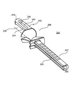
portion 343 of the extension member 308 may engage the back edge of the recess
326.
In the extended position (as shown in FIG. 3C), the lip 361 may engage the
protrusions 381, 382, thereby limiting the distance. In order to remove the
pusher
member 304 from the handle 306, the lip 361 may be pushed down such that the
proximal end portion 343 bends towards the surface of the recess 326. Then,
the lip
361 may slide underneath the protrusions 381, 382, thereby de-coupling the
pusher
member 304 from the handle 306. Then, the pusher member 304 may be distally
moved along the needle member 302, and the pusher member 304 may be removed
from the needle member 302 through the slot defined by the pusher member 304.
[0084] FIGS. 4A-4C illustrates a pusher member 404 and a handle 406
according to various aspects. FIG. 4A illustrates a perspective of the pusher
member
404 having a sheath 407, a handle portion 409, and an extension member 408.
The
sheath 407 and the handle portion 409 may be the same as the sheath 207 and
the
handle portion 209 described with reference to FIGS. 2A-2G, and therefore the
details
of these components will be omitted for the sake of brevity. FIG. 4B
illustrates a
perspective of the handle 406. FIG. 4C illustrates the pusher member 404
coupled to
the handle 406 with a needle member 402 coupled to the handle 406 and
extending
through the pusher member 404.
[0085] In the aspects of FIGS. 4A-4C , the extension member 408 of the
pusher member 404 may define a prong having two extensions 470, 471 with
enlarged
portions 472, 473, and the handle 406 may include tapered portions 475, 476
configured to engage the enlarged portions 472, 473 to limit a travel distance
of the
pusher member 404 during the surgical procedure. The pusher member 404 may be
removed the handle 406 may applying additional force in the distal direction
such that
the enlarged portions 472, 473 are moved closer together to fit past the
tapered
portions 475, 476.
19
CA 02957309 2017-02-03
WO 2016/022649
PCT/US2015/043762
[0086] Referring to FIG. 4A, the extension member 408 may extend from the
end of the handle portion 409. The extension member 408 may extend in a
direction
parallel with a longitudinal axis 459 of the pusher member 404. The extension
member 408 may define a prong having a first extension member 470 and a second
extension member 471. The first extension member 470 may be parallel with the
second extension member 471. The first extension member 470 may be spaced part
from the second member extension 471, thereby creating an opening 474 between
the
first extension member 470 and the second extension member 471. The proximal
end
portion of the first extension member 470 may include a first enlarged portion
472.
The proximal end portion of the second extension member 471 may include a
second
enlarged portion 473. The first enlarged portion 472 may be aligned with the
second
enlarged portion 473 in relation to the location along the length of the
extension
member 408. The first enlarged portion 472 may have a width greater than other
portions of the first extension member 470. The second enlarged portion 473
may
have a width greater than other portions of the second enlarged portion 473.
The
width of the first enlarged portion 472 may be the same as the width of the
second
enlarged portion 473. The opening 474 between the first enlarged portion 472
and the
second enlarged portion 473 may be smaller than the opening 474 between the
non-
enlarged portions of the first extension member 470 and the non-enlarged
portions of
the second extension member 471.
[0087] Referring to FIG. 4B, the handle 406 may include a track portion
411
that couples the extension member 408, and an opening 430 configured to
receive the
needle member 402. The track portion 411 may include a recess 426, a first
tapered
portion 475, and a second tapered portion 476. Similar to the handle 306 of
FIG. 3B,
the recess 426 may have a shape that substantially corresponds to the shape of
the
extension member 408 such that the extension member 408 can fit and slide
within
the recess 426.
[0088] The first tapered portion 475 may be a portion of the handle 406
that
extends into the recess 426 on a first side of the recess 426. The second
tapered
portion 476 may be a portion of the handle 406 that extends into the recess
426 on a
second side of the recess. The first tapered portion 475 and the second
tapered
portion 476 may be aligned in the same location with respect to the length of
the
recess. The first tapered portion 475 and the second tapered portion 476 may
be
CA 02957309 2017-02-03
WO 2016/022649
PCT/US2015/043762
disposed on the distal end portion of the handle 406. The width of the recess
426 at
the location of the tapered portions 475, 476 may be smaller the width of
other
portions of the recess 426.
[0089] Referring to FIG. 4C, the extension member 408 may be configured
to
slide in relation to the handle 406. For example, the extension member 408 may
be
disposed within the recess 426, and the extension member 408 may be configured
to
travel the distance between the tapered portions 475, 476 and the back edge of
the
recess 426. In the retracted position, the tapered portions 475, 476 may
engage the
back edge of the recess 426. In the extended position (as shown in FIG. 4C),
the
enlarged portions 472, 473 may engage the tapered portions 475, 476, thereby
limiting the distance during a surgical procedure. The pusher member 404 may
be
removed the handle 406 may applying additional force in the distal direction
such that
the enlarged portions 472, 473 are moved closer together (thereby decreasing
the
opening 474) in order to fit past the tapered portions 475, 476.
[0090] FIGS. 5A-5E illustrate various positions of a pusher member 504 in
relation to a handle 506 and a needle member 502 in order to decouple the
pusher
member 504 from the handle 506 and the needle member 502 according to various
aspects. FIG. 5A illustrates the pusher member 504 in a first position. FIG.
5B
illustrates the pusher member 504 in a second position. FIG. 5C illustrates
the pusher
member 504 in a fourth position. FIG. 5D illustrates the pusher member 504 in
a fifth
position. FIG. 5E illustrates the pusher member 504 in a sixth position.
[0091] Referring to FIG. 5A, the pusher member 504 is within the
retracted
position. The pusher member 504 may include a sheath 507, a handle portion
509,
and an extension member 508 (see FIGS. 5B-E). As indicated above, the sheath
507
and the handle portion 509 may define a lumen. The needle member 502 extends
through the lumen of the sheath 507 and the handle portion 509, and the needle
member 502 is coupled to the handle 506. Also, the sheath 507 and the handle
portion 509 define a slot 520 (see FIG. 5D-5E) that extends the length of the
sheath
507 and the handle portion 509.
[0092] Referring to FIG. 5B, the pusher member 504 is distally moved away
from the handle 506 along the axis A2. In this example, the pusher member 504
has
already been de-coupled from the handle 506. For example, the pusher member
504
may been de-coupled in any of the manners previously described with reference
to
21
CA 02957309 2017-02-03
WO 2016/022649
PCT/US2015/043762
FIGS. 1-4. As such, after the pusher member 504 is de-coupled from the handle
506,
the pusher member 504 may be moved a further distance to the position as shown
in
FIG. 5B. For example, a relatively small distance may exist between the
extension
member 508 and the handle 506. Also, the extension member 508 may be still
aligned with the track portion of the handle 506.
[0093] Referring to FIG. 5C, the pusher member 504 may be rotated about
the
needle member 502. For example, the pusher member 504 may be rotated clockwise
or counter clockwise. In some examples, the pusher member 504 may be rotated
until
the slot 520 is aligned with a curved portion of the needle member 502.
100941 Referring to FIG. 5D, the pusher member 504 is further moved along
the needle member 502 along the axis A2. In some examples, the pusher member
504
is moved to a position where a portion of the pusher member 504 is not
disposed
around the needle member 502. In some examples, the pusher member 504 is moved
to a reduced-diameter portion (e.g., as discussed in FIGS. 2A-2C) such that at
least a
portion of the sheath 507 and/or the handle portion 509 aligns with the
reduced-
diameter portion of the needle member 502. Referring to FIG. 5E, the pusher
member
504 is removed from the needle member 502 by sliding the pusher member 504 in
any
directions perpendicular to the axis 2 (e.g., along the axis A3) such that
pusher
member 504 slides off the needle member 502 through the slot 520.
[0095] FIGS. 6A-6D illustrate various examples of a medical device 600
having a needle member 602, a pusher member 604, and a handle 606 that can be
disassembled and reassembled according to various aspects.
[0096] Referring to FIG. 6A, the needle member 602 may include a curved
portion 620. In some examples, the needle member 602 may include multiple
curved
portions such that the curved portions extend in two or three dimension
planes. In
other examples, the needle member 602 may be substantially straight. The
needle
member 602 may include a cylindrical structure. In other examples, the needle
member 602 may include portions having a non-cylindrical shape. In some
examples,
the non-cylindrical shape may be a d-shaped structure having a rounded side
and a flat
side. The d-shaped structure of the needle member 602 in conjunction with a d-
shaped opening on the handle 606 may allow the curved portion 620 of the
needle
member 602 to be properly orientated, as further described below.
22
CA 02957309 2017-02-03
WO 2016/022649
PCT/US2015/043762
[0097] Also, the needle member 602 may include a distal end portion 601
and
a proximal end portion 603. The distal end portion 601 may be configured to
pierce
bodily tissue. In some examples, the distal end portion 601 may be sharp. In
some
examples, the distal end portion 601 may be blunt or rounded. In some
examples, the
distal end portion 601 may include a coupling member (e.g., slot) that is
configured to
couple an implant to the needle member 602. The proximal end portion 603 of
the
needle member 602 may be coupled to a securing member 614. In some examples,
the securing member 614 may be a knob. However, generally, the securing member
614 may be any type of structure configured to be coupled to the proximal end
portion
603 of the needle member 602. In some examples, as shown in FIG. 6A, the
proximal
end portion 603 may include a male thread 616 to be coupled with a female
thread
618 of the securing member 614 in order to couple the needle member 602 to the
handle 606. In other examples, the proximal end portion 603 may include the
female
thread 618, and the securing member 614 may include the male thread 616.
However,
the proximal end portion 603 and the securing member 614 may include any type
of
fastener/keyway arrangements.
[0098] As shown in FIG. 6A, the pusher member 604 may include a sheath
607, a handle portion 609, and an extension member 608. The sheath 607 and the
handle portion 609 may define a lumen such that the needle member 602 can
extend
through the sheath 607 and the handle portion 609. The sheath 607 may be any
of the
sheaths described with reference to the previous figures, and the handle
portion 609
may bc any of the handle portions described with reference to the previous
figures.
However, in some examples, the sheath 607 and the handle portion 609 do not
define
a slot (e.g., slot 220). In other examples, the sheath 607 and the handle
portion 609
include the slot. The extension member 608 may be any of the extension members
described with reference to the previous figures.
[0099] The handle 606 may be any of the handles described with reference
to
the previous figures. However, the handle 606 also may include a lumen 612
that
extends a length of the handle 606. As shown in FIG. 6A, the proximal end
portion
603 may be inserted through the lumen 650 of the sheath 607 and the handle
portion
609. The proximal end portion 603 may be further inserted within the lumen 612
of
the handle 606. Then, a portion of the securing member 614 may be inserted
into the
lumen 612 from the other side of the handle 606. The securing member 614 may
be
23
CA 02957309 2017-02-03
WO 2016/022649
PCT/US2015/043762
manipulated to couple the needle member 602 to the handle 606. In some
examples,
the male thread 616 of the proximal end portion 603 may engage the female
thread
618 of the securing member 614, and the securing member 614 may be rotated,
thereby coupling the handle 606 to the needle member 602.
1001001 FIG. 6B illustrates an opening 613 on the handle 606 according to
an
aspect. The opening 613 may be configured to receive the proximal end portion
603
of the needle member 602 after it is inserted through the pusher member 604.
In
some examples, as shown in FIG. 6B, the needle member 602 may have portions
that
are non-cylindrical. Then, the shape of the opening 613 may be configured to
correspond to the shape of the needle member 602. In this manner, the correct
orientation of the needle member 602 relative to the handle 606 may be
ensured. In
some examples, the needle member 602 may be d-shaped having a flat side. In
this
example, the opening 613 may also be d-shaped in order to position the needle
member 602 in a certain orientation.
[00101] FIG. 6C illustrates a cross-section view depicting the needle
member
602 secured to the handle 606 using the securing member 614. As shown, in FIG.
6C,
the proximal end portion 603 of the needle member 602 includes the male thread
616.
The securing member 614 includes the female thread 618. In the locked
configuration
as shown in FIG. 6C, a first portion 690 of the needle member 602 extends from
the
opening 613 through the handle portion 609 and the sheath 607, and a second
portion
691 of the needle member 602 is disposed within the handle 606. The second
portion
691 includes the male thread 616 and a portion 692 that extends beyond the
male
thread 616. As shown in FIG. 6C, the needle member 602 does not extend through
the length of the handle 606. In some examples, the securing member 614 may be
disposed entirely within the handle 606. In other examples, the securing
member 614
may be partially disposed within the handle 606.
[00102] FIG. 6D illustrates the medical device 600 as assembled according
to
an aspect. As shown in FIG. 6D, the needle member 602 is coupled to the handle
606
using the securing member 614, and the needle member 602 is disposed within a
lumen defined by the pusher member 604 such that the pusher member 604 can
move
relative to the handle 606.
[00103] FIGS. 7A and 7B illustrate a medical device 700 according to
another
aspect. FIG. 7A illustrates a side view of the medical device 700. FIG. 7B
illustrates
24
CA 02957309 2017-02-03
WO 2016/022649
PCT/US2015/043762
a top view of the medical device 700. The medical device 700 may be considered
a
re-usable medical delivery device since at least some of its components can be
disassembled, sterilized, and then re-assembled for future use. Also, the
medical
device 700 may incorporate features and/or components described with reference
to
the previous figures. The medical device 700 may include a needle member 702
and
a handle 706. In some examples, the needle member 702 and the handle 706 may
be
any of the needle members and handles with respect to any of the other figures
described herein. In some aspects, the needle member 702 may be removably
coupled to the handle 706 such that the needle member 702 and the handle 706
may
be disassembled and re-assembled in order to allow the medical device 700 to
be re-
used. Furthermore, in some examples, the medical device 700 may also include
any
of the previously described pusher members. As such, the needle member 702 and
the handle 706 may include previously described features that permit the
medical
device 700 to include a removable pusher member as previously described. The
needle member 702 may include a coupling member 703 (e.g., a slot, L-shaped)
configured to couple an implant. In some examples, the coupling member 703 may
be disposed on the distal end portion of the needle member 702. The needle
member
702 may include one or more curved portions. The needle member 702 may be
removably coupled to the handle 706. The medical device 700 may include a
fastening mechanism to removably couple the needle member 702 to the handle
706.
In some examples, the needle member 702 may include a fastening member 705
configured to be coupled to the handle 706. In some examples, the fastening
member
705 may be fixedly coupled to the proximal end portion of the needle member
702.
In some examples, the fastening member 705 may be inserted into an opening or
cavity of the handle 706. The handle 706 may include a secondary fastening
member
configured to be removably coupled to the fastening member 705. The secondary
fastening member may be disposed within the opening or cavity of the handle
706. In
some examples, the fastening member 705 may be a threaded (male or female)
member to be coupled with a threaded (male or female) member of the handle
706.
However, the medical device 700 may incorporate any type of fastening
mechanism
to removably couple the needle member 702 to the handle 706.
1001041 FIG. 8 illustrates a medical device 800 according to another
aspect.
The medical device 800 may be considered a re-usable medical delivery device
since
CA 02957309 2017-02-03
WO 2016/022649
PCT/US2015/043762
at least some of its components can be disassembled, sterilized, and then re-
assembled
for future use. Also, the medical device 800 may incorporate features and/or
components described with reference to the previous figures. The medical
device 800
may include a needle member 802 and a handle 806. The needle member 802 may
include a coupling member 803 (e.g., a slot, L-shaped) configured to couple an
implant In some examples, the coupling member 803 may be disposed on the
distal
end portion of the needle member 802. The needle member 802 may include one or
more curved portions that may be different than the curvature of the needle
member
702. The needle member 802 may be removably coupled to the handle 806. In some
examples, the needle member 802 and the handle 806 may be any of the needle
members and handles with respect to any of the other figures described herein.
In
some aspects, the needle member 802 may be removably coupled to the handle 806
such that the needle member 802 and the handle 806 may be disassembled and re-
assembled in order to allow the medical device 800 to be re-used. Furthermore,
in
some examples, the medical device 800 may also include any of the previously
described pusher members. As such, the needle member 802 and the handle 806
may
include previously described features that permit the medical device 800 to
include a
removable pusher member as previously described. The medical device 800 may
include a fastening mechanism to removably couple the needle member 802 to the
handle 806. In some examples, the needle member 802 may include a fastening
member 805 configured to be coupled to the handle 806. In some examples, the
fastening member 805 may be fixedly coupled to the proximal end portion of the
needle member 802. In some examples, the fastening member 805 may be inserted
into an opening or cavity of the handle 806. The handle 806 may include a
secondary
fastening member configured to be removably coupled to the fastening member
805.
The secondary fastening member may be disposed within the opening or cavity of
the
handle 806. In some examples, the fastening member 805 may be a threaded (male
or
female) member to be coupled with a threaded (male or female) member of the
handle
806. However, the aspects incorporate any type of fastening mechanism to
removably
couple the needle member 802 to the handle 806.
1001051 FIG. 9 illustrates a medical device 900 according to another
aspect.
The medical device 900 may be considered a re-usable medical delivery device
since
at least some of its components can be disassembled, sterilized, and then re-
assembled
26
CA 02957309 2017-02-03
WO 2016/022649
PCT/US2015/043762
for future use. Also, the medical device 900 may incorporate features and/or
components described with reference to the previous figures. The medical
device 900
may include a needle member 902 and a handle 906. The needle member 902 may
include one or more bent portions. The needle member 902 may be removably
coupled to the handle 906. In some examples, the needle member 902 and the
handle
906 may be any of the needle members and handles with respect to any of the
other
figures described herein. In some aspects, the needle member 902 may be
removably
coupled to the handle 906 such that the needle member 902 and the handle 906
may
be disassembled and re-assembled in order to allow the medical device 900 to
be re-
used. Furthermore, in some examples, the medical device 900 may also include
any
of the previously described pusher members. As such, the needle member 902 and
the handle 906 may include previously described features that permit the
medical
device 900 to include a removable pusher member as previously described. The
medical device 900 may include a fastening mechanism to removably couple the
needle member 902 to the handle 906. In some examples, the needle member 902
may include a fastening member 905 configured to be coupled to the handle 906.
In
some examples, the fastening member 905 may be fixedly coupled to the proximal
end portion of the needle member 902. In some examples, the fastening member
905
may be inserted into an opening or cavity of the handle 906. The handle 906
may
include a secondary fastening member configured to be removably coupled to the
fastening member 905. The secondary fastening member may be disposed within
the
opening or cavity of the handle 906. In some examples, the fastening member
905
may be a threaded (male or female) member to be coupled with a threaded (male
or
female) member of the handle 906. However, the aspects incorporate any type of
fastening mechanism to removably couple the needle member 902 to the handle
906.
[00106] FIG. 10 illustrates a medical device 1000 according to another
aspect.
The medical device 1000 may be considered a re-usable medical delivery device
since
at least some of its components can be disassembled, sterilized, and then re-
assembled
for future use. Also, the medical device 1000 may incorporate features and/or
components described with reference to the previous figures. The medical
device
1000 may include a needle member 1002 and a handle 1006. The needle member
1002 may include one or more bent portions. The needle member 1002 may be
removably coupled to the handle 1006. In some examples, the needle member 1002
27
CA 02957309 2017-02-03
WO 2016/022649
PCT/US2015/043762
and the handle 1006 may be any of the needle members and handles with respect
to
any of the other figures described herein. In some aspects, the needle member
1002
may be removably coupled to the handle 1006 such that the needle member 1002
and
the handle 1006 may be disassembled and re-assembled in order to allow the
medical
device 1000 to be re-used. Furthermore, in some examples, the medical device
1000
may also include any of the previously described pusher members. As such, the
needle member 1002 and the handle 1006 may include previously described
features
that permit the medical device 1000 to include a removable pusher member as
previously described. The medical device 1000 may include a fastening
mechanism
to removably couple the needle member 1002 to the handle 1006. In some
examples,
the needle member 1002 may include a fastening member 1005 configured to be
coupled to the handle 1006. In some examples, the fastening member 1005 may be
fixedly coupled to the proximal end portion of the needle member 1002. In some
examples, the fastening member 905 may be inserted into an opening or cavity
of the
handle 1006. The handle 1006 may include a secondary fastening member
configured
to be removably coupled to the fastening member 1005. The secondary fastening
member may be disposed within the opening or cavity of the handle 1006. In
some
examples, the fastening member 1005 may be a threaded (male or female) member
to
be coupled with a threaded (male or female) member of the handle 1006.
However,
the aspects incorporate any type of fastening mechanism to removably couple
the
needle member 1002 to the handle 1006.
[00107] FIG. 11 illustrates a flowchart 1100 for a method of re-using a
medical
device according to an aspect. For example, after the medical device is used
within a
surgical procedure, the following steps may be performed to help to
disassemble the
medical device to permit the medical device to be re-used. The medical device
may
be any of the medical devices described herein. In some examples, the medical
device may be the medical devices described in FIGS. 1-5. For example, the
medical
device may include a pusher member, a needle member, and a handle.
[00108] In step 1102, the pusher member may be de-coupled from the handle.
In some examples, the pusher member may be de-coupled from the handle by
rotating
the pusher member as discussed in FIGS. 2A-2G. In some examples, the pusher
member may move to the extended position. Then, the pusher member may rotate
28
CA 02957309 2017-02-03
WO 2016/022649
PCT/US2015/043762
about its longitudinal axis. The rotation of the pusher member may cause the
pusher
member to be de-coupled from the handle.
[00109] In sonic
examples, the pusher member may rotate off the handle
through a slot defined on the pusher member. The slot may be disposed on a
side
portion of the extension member. In particular, the handle may defme a track
portion,
and the extension member of the pusher member may be configured to be slidably
disposed in the track portion. The extension member of the pusher member may
define the slot. The track portion of the handle may define a recess to
receive the
extension member. Also, the handle may define a protrusion extending from the
recess of the track portion. In some examples, the protrusion may extend from
an end
portion of the recess. Also, the extension member may define an opening that
extends
into the slot. The protrusion of the handle may be disposed within the opening
of the
extension member such that the protrusion limits the travel distance of the
pusher
member during the medical procedure when the extension member engages the
protrusion. However, by rotating the pusher member, the protrusion of the
handle
moves through the slot of the extension member of the pusher member, thereby
de-
coupling the pusher member from the handle.
[00110] In some
examples, the pusher member may be de-coupled from the
handle by applying a pressure to a portion of the extension member of the
pusher
member, as described in FIGS. 3A-D. In some examples, the pusher may be de-
coupled from the handle by applying a distal force greater than the force used
to move
the pusher member during the surgical procedure, as discussed in FIGS. 4A-C.
[00111] In step 1104,
the pusher member may be decoupled from the needle
member. In some examples, the pusher member may be decoupled from the needle
member as described with reference to FIGS. 1-5. For example, the pusher
member
may define a slot or opening on the side of the pusher member, and the pusher
member may be removed from the needle member through the slot or opening a
direction different than an axis that defines the movement of the pusher
during the
medical procedure. In step 1106, the medical device may be sterilized such
that the
medical device can be re-assembled and then used in a subsequent medical
procedure.
[00112] FIG. 12
illustrates a flowchart 1200 for a method of re-using a
medical device according to an aspect. For example, after the medical device
is used
within a surgical procedure, the following steps may be performed to help to
29
CA 02957309 2017-02-03
WO 2016/022649
PCT/US2015/043762
disassemble the medical device to permit the medical device to be re-used. The
medical device may be any of the medical devices described herein. In some
examples, the medical device may be the medical devices described in FIG.6.
For
example, the medical device may include a pusher member, a needle member, a
handle, and a securing member.
[00113] In step 1202, the securing member may be decoupled from the needle
member. For example, the proximal end portion of the needle member may extend
through a first opening of the handle into a cavity defined by the handle, the
securing
member may extend through a second opening of the handle into the cavity of
the
handle, and the securing member and the proximal end portion of the needle
member
may be removably coupled. In some examples, the securing member may be rotated
to decouple the securing member from the proximal end portion of the needle
member.
[00114] In step 1204, the needle member may be removed from the handle.
For example, the proximal end portion of the needle member may move out of the
first opening of the handle. In step 1206, the pusher member may be removed
from
the handle. For example, the pusher member may be slide over the proximal end
portion of the needle member. In this manner, the pusher member, the needle
member, and the handle may be separated. In step 1208, the medical device may
be
sterilized such that the medical device can be re-assembled and then used in a
subsequent medical procedure.
[00115] In a general aspect, a medical device may include a needle member,
and a handle coupled to the needle member. The handle may define a track
portion.
The medical device may also include a pusher member including a sheath
defining a
lumen configured to receive a portion of the needle member and an extension
member
being movably coupled to the track portion of the handle such that the pusher
member
is configured to move from a first position to a second position during a
surgical
procedure. The pusher member may be removable from the handle. The sheath may
define a slot. The pusher member may be removable from the needle member
through the slot or the lumen.
[00116] The track portion may define a recess, and at least a portion of
the
extension member is disposed within the recess. The track portion may include
at
least one protrusion. The track portion may include a tapered portion. The
pusher
CA 02957309 2017-02-03
WO 2016/022649
PCT/US2015/043762
member may be removable from the handle based on a rotation of the pusher
member.
The extension member may define a slot. The pusher member may be removable
from the handle based on a rotation through the slot of the extension member.
The
extension member may include a flexible lip, and the pusher member is
removable
from the handle based on a force applied to the flexible lip. The pusher
member may
be removable from the handle by applying a force to the pusher member, where
the
force is greater than a force used to move the pusher member from the first
position to
the second position during the surgical procedure. The extension member may
define
a first extension member and a second extension member. The extension member
may define an opening between the first extension member and the second
extension
member. The slot may extend in a direction parallel to a longitudinal axis of
the
pusher member. The pusher member may further include a handle portion The
handle portion may be disposed between the extension member and the sheath.
The
handle portion may be configured to be disposed around the portion of the
needle
member. The sheath and the handle portion define the slot. The handle portion
may
include a proximal end portion, where the extension member extends from a
surface
of the proximal end portion of the extension member. The handle defines a
first
opening, a second opening, and a lumen between the first opening and the
second
opening, where a proximal end portion of the needle member extends into the
lumen
through the first opening. The medical device may further include a securing
member
configured to be inserted into the lumen through the second opening of the
handle.
The securing member is configured to be removably coupled to the proximal end
portion of the needle member. The proximal end portion of the needle member
may
include a first threaded fastener portion and the securing member may include
a
second threaded fastener portion.
[00117] According to another aspect, a medical device may include a needle
member, a handle coupled to the needle member. The handle defines a track
portion.
The medical device may also include a pusher member including a sheath
disposed
around a portion of the needle member and an extension member being movably
coupled to the track portion of the handle such that the pusher member is
configured
to move from a first position to a second position during a surgical
procedure. The
pusher member is removable from the handle. The sheath defines a slot. The
pusher
member is removable from the needle member through the slot. The track portion
31
CA 02957309 2017-02-03
WO 2016/022649
PCT/US2015/043762
defines a recess, where at least a portion of the extension member is disposed
within
the recess. The track portion may include at least one protrusion. The track
portion
may include a tapered portion. The pusher member is removable from the handle
based on a rotation of the pusher member. The extension member may define a
slot,
the pusher member is removable from the handle based on a rotation through the
slot
of the extension member. The extension member may include a flexible lip, and
the
pusher member is removable from the handle based on a force applied to the
flexible
lip. The pusher member may be removable from the handle by applying a force to
the
pusher member, where the force is greater than a force used to move the pusher
member from the first position to the second position during the surgical
procedure.
The extension member may define a first extension member and a second
extension
member, where the extension member defines an opening between the first
extension
member and the second extension member. The slot may extend in a direction
parallel to a longitudinal axis of the pusher member. The pusher member may
further
include a handle portion. The handle portion is disposed between the extension
member and the sheath. The handle portion may be configured to be disposed
around
the portion of the needle member such that the sheath and the handle portion
define
the slot. The handle portion may include a proximal end portion, where the
extension
member extends from a surface of the proximal end portion of the extension
member.
[00118] According to another aspect, a medical device may include a needle
member having a proximal end portion, and a handle coupled to the proximal end
portion of the needle member. The handle defines a track portion. The medical
device may further include a pusher member including a sheath disposed around
a
portion of the needle member, a handle portion disposed around the portion of
the
needle member, and an extension member movably coupled to the track portion of
the
handle such that the pusher member is configured to move from a first position
to a
second position during a surgical procedure. The pusher member may be
removable
from the handle when not used within the surgical procedure. The sheath and
the
handle portion define a slot, and the pusher member is removable from the
needle
member through the slot. The track portion defines a recess, where at least a
portion
of the extension member is disposed within the recess. The handle portion
includes a
proximal end portion, where the extension member extends from a surface of the
32
CA 02957309 2017-02-03
WO 2016/022649
PCT/US2015/043762
proximal end portion of the extension member. The slot may extend in a
direction
parallel to a longitudinal axis of the pusher member.
[00119] According to another aspect, a medical device may include a needle
member having a proximal end portion, and a handle defining a first opening, a
second opening, and a lumen between the first opening and the second opening.
The
proximal end portion of the needle member extends into the lumen through the
first
opening. The medical device may further include a securing member configured
to be
inserted into the lumen through the second opening of the handle. The securing
member is configured to be removably coupled to the proximal end portion of
the
needle member. The medical device may further include a pusher member
including
a sheath disposed around a portion of the needle member, where the pusher
member is
configured to move from a first position to a second position in relation to
the handle
during a surgical procedure.
[00120] The pusher member may be removably coupled to the handle. The
handle defines a track portion, and the pusher member includes an extension
member.
The extension member may be configured to be movably coupled to the track
portion.
The proximal end portion may include a first threaded fastener portion and the
securing member may include a second threaded fastener portion.
[00121] While certain features of the described implementations have been
illustrated as described herein, many modifications, substitutions, changes
and
equivalents will now occur to those skilled in the art. It is, therefore, to
be understood
that the appended claims are intended to cover all such modifications and
changes as
fall within the scope of the embodiments.
33