Note: Descriptions are shown in the official language in which they were submitted.
CA 02957346 2017-02-08
SURGICAL INSTRUMENT INCLUDING ROTATING
END EFFECTOR AND ROTATION-LIMITING STRUCTURE
CROSS REFERENCE TO RELATED APPLICATIONS
[0001] This application is a continuation-in-part of U.S. Patent
Application No.
13/974,371 filed on August 23, 2013, which is a continuation-in-part of U.S.
Patent
Application No. 13/974,338 filed on August 23, 2013, which is a continuation-
in-part of U.S.
Patent Application No. 13/930,770, filed on June 28, 2013, and the disclosures
of each of the
above-identified applications are hereby incorporated by reference in their
entirety.
BACKGROUND
Technical Field
[0002] The present disclosure relates to surgical instruments, devices
and/or systems
for performing endoscopic surgical procedures and methods of use thereof. More
specifically, the present disclosure relates to surgical instruments, devices
and/or systems
including an end effector that is able to articulate, rotate and have a
limited amount of
rotation.
Background of Related Art
[0003] During laparoscopic or endoscopic surgical procedures, access to a
surgical
site is typically achieved through a small incision or through a narrow
cannula inserted
through a small entrance wound in a patient. Because of limited area to access
the surgical
site, many endoscopic surgical devices include mechanisms for articulating or
rotating the
tool assembly or the end effector of the device.
[0004] In surgical instruments that are used to apply tacks or anchors
having helical
threads, for example, an additional challenge exists when attempting to rotate
the end
1
CA 02957346 2017-02-08
effector, as the tacks are also configured to rotate through the end effector,
through a surgical
mesh, and into tissue, for instance.
[0005] Accordingly, a need exists for tack-applying surgical instruments
which
include the ability for its end effector to articulate and rotate, while also
limiting the overall
amount of rotation to prevent the premature ejection of tacks and to prevent
timing issues
when attempting to eject tacks.
SUMMARY
[0006] The present disclosure relates to a surgical instrument configured
to apply
tacks to tissue. The surgical instrument includes a handle assembly, an
elongated portion, an
outer tube, an end effector, a rotation assembly, and a rotation-limiting
structure. The
elongated portion extends distally from the handle assembly and defines a
first longitudinal
axis. The outer tube extends distally from the handle assembly. The end
effector is disposed
adjacent a portion of the elongated portion and is configured to house a
plurality of tacks
therein. The end effector defines a second longitudinal axis. The rotation
assembly is
configured to rotate at least a portion of the outer tube about the first
longitudinal axis and
with respect to the handle assembly. The rotation assembly includes a rotation
knob
rotationally fixed to a proximal portion of the outer tube. The rotation-
limiting structure is
disposed in mechanical cooperation with at least one of the rotation assembly
and the handle
assembly, and is configured to limit an amount of rotation of the outer tube
with respect to
the handle assembly.
[0007] In embodiments, the rotation-limiting structure includes at least
one projection
extending from a portion of the rotation knob. It is disclosed that the
rotation-limiting
structure includes at least one lip disposed within the handle assembly. It is
further disclosed
that a first projection of the at least one projection is configured to
contact a first lip of the at
2
CA 02957346 2017-02-08
least one lip upon a predetermined amount of rotation of the rotation knob in
a first direction.
Additionally, it is disclosed that a second projection of the at least one
projection is
configured to contact a second lip of the at least one lip upon a
predetermined amount of
rotation of the rotation knob in a second direction. It is also disclosed that
the predetermined
amount of rotation of the rotation knob in the first direction is about 45 ,
and the
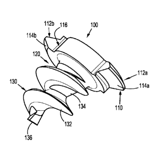
predetermined amount of rotation of the rotation knob in the second direction
is about 45 .
[0008] In disclosed embodiments, the rotation knob includes a non-
circular transverse
cross-section, where the transverse cross-section is taken perpendicular to
the first
longitudinal axis.
[0009] It is further disclosed that at least a portion of the end
effector is rotationally
fixed with respect to the outer tube.
[0010] Additionally, it is disclosed that the rotation assembly is
configured to rotate at
least a portion of the end effector about the second longitudinal axis.
[0011] In disclosed embodiments, the surgical instrument further includes
a plurality
of helical tacks disposed at least partially within the end effector.
[0012] It is also disclosed that the surgical instrument further includes
an articulation
assembly configured to move the end effector from a first position where the
second
longitudinal axis is coaxial with the first longitudinal axis, to a second
position where the
second longitudinal axis is disposed at an angle with respect to the first
longitudinal axis. It
is further disclosed that the articulation assembly includes an articulation
knob that is
rotatable about the first longitudinal axis with respect to the proximal
portion of the outer
tube.
[0013] The present disclosure also relates to a method of applying
surgical tacks from
a surgical instrument to tissue. The method includes articulating an end
effector of the
surgical instrument from a first position where the end effector is
longitudinally aligned with
3
CA 02957346 2017-02-08
an elongated portion of the surgical instrument, to a second position where
the end effector is
disposed at an angle with respect to the elongated portion. The method further
includes
rotating the end effector a first amount in a first direction with respect to
a handle assembly
of the surgical instrument. The method further includes limiting the amount of
rotation of the
end effector in the first direction to a first predetermined amount of
rotation, and ejecting at
least one surgical tack from the surgical instrument.
[0014] In disclosed embodiments, the method further includes limiting the
first
predetermined amount of rotation to about 45 .
[0015] Embodiments of the method further include rotating the end
effector a second
amount in a second direction with respect to a handle assembly of the surgical
instrument. It
is disclosed that the method also includes limiting the amount of rotation of
the end effector
in the second direction to a second predetermined amount of rotation, and that
the second
predetermined amount of rotation is about 45 .
[0016] In embodiments, articulating the end effector is performed
independently of
rotating the end effector.
4
CA 02957346 2017-02-08
a
BRIEF DESCRIPTION OF THE DRAWINGS
[0017] Various aspects of the present disclosure are described
hereinbelow with
reference to the drawings, which are incorporated and constitute a part of
this specification,
wherein:
[0018] FIG. 1 is a perspective view of a surgical anchor for use in
an endoscopic
surgical device in accordance with the present disclosure;
[0019] FIG. 2 is a side, elevational view of the surgical anchor of
FIG. 1;
[0020] FIG. 3 is a distal, end view of the surgical anchor of FIGS.
1 and 2;
[0021] FIG. 4 is a side, elevational view, partially broken away,
of the surgical anchor
of FIGS. 1-3;
[0022] FIG. 5 is an endoscopic surgical device according to an
aspect of the present
disclosure;
[0023] FIG. 6 is a perspective view, with parts separated, of the
endoscopic surgical
device of FIG. 5;
[0024] FIG. 7 is an enlarged view of the indicated area of detail
of FIG. 6;
[0025] FIG. 8 is a rear perspective view, with a first housing half-
section removed
therefrom, of a handle assembly of the endoscopic surgical device of FIG. 5;
[0026] FIG. 9 is a front perspective view, with a second housing
half-section removed
therefrom, of a handle assembly of the endoscopic surgical device of FIG. 5;
[0027] FIG. 10 is a rear perspective view, with a second housing
half-section and
trigger removed therefrom, of the handle assembly of the endoscopic surgical
device of FIG.
5;
[0028] FIG. 11 is a rear perspective view, with parts separated,
and with a second
housing half-section removed therefrom, of the handle assembly of the
endoscopic surgical
device of FIG. 5;
CA 02957346 2017-02-08
[0029] FIG. 12 is a perspective view of a pinion gear of the handle
assembly of FIGS.
8-11;
[0030] FIG. 13 is a perspective view of a button and slider of the handle
assembly of
FIGS. 8-11;
[0031] FIG. 14 is a perspective view of a bevel gear of the handle
assembly of FIGS.
8-11;
[0032] FIG. 15 is a front perspective view, with parts separated, of an
endoscopic
assembly of the endoscopic surgical device of FIG. 5;
[0033] FIG. 16 is an enlarged view of the indicated area of detail of
FIG. 15;
[0034] FIG. 17 is a rear perspective view of the endoscopic surgical
device of FIG. 5;
[0035] FIG. 18 is an enlarged view of the indicated area of detail of
FIG. 17;
[0036] FIG. 19 is a perspective view of the distal end of the endoscopic
surgical
device of FIG. 5 with an end effector shown separated therefrom;
[0037] FIG. 20 is a rear perspective view of the end effector of FIG. 19;
[0038] FIG. 21 is a rear perspective view of the end effector of FIG. 20,
with an outer
tube removed therefrom;
[0039] FIG. 22 is a perspective view of the end effector of FIGS. 20 and
21, with an
outer tube separated therefrom;
[0040] FIG. 23 is a perspective view of the end effector of FIGS. 20-22,
with an outer
tube removed therefrom and with parts partially separated;
[0041] FIG. 24 is a perspective view of an inner tube of the end effector
of FIGS. 20-
23, with a plurality of anchors of FIGS. 1-4 shown separated therefrom;
[0042] FIG. 25 is a cross-sectional view, as taken along 25-25 of FIG.
22;
[0043] FIG. 26 is a cross-sectional view, as taken along 26-26 of FIG.
22;
[0044] FIG. 27 is a cross-sectional view, as taken along 27-27 of FIG.
22;
6
CA 02957346 2017-02-08
[0045] FIG. 28 is a perspective view of the end effector of FIGS. 20-27
with a
shipping wedge shown attached thereto;
[0046] FIG. 29 is a cross-sectional view as taken through 29-29 of FIG.
28;
[0047] FIG. 30 is a cross-sectional view as taken through 30-30 of FIG.
29;
[0048] FIG. 31 is a longitudinal, cross-sectional, elevational view of the
endoscopic
surgical device of FIG. 5;
[0049] FIG. 32 is an enlarged view of the indicated area of detail of FIG.
31;
[0050] FIG. 33 is an enlarged view of the indicated area of detail of FIG.
31;
[0051] FIG. 34 is a cross-sectional view as taken though 34-34 of FIG. 31;
[0052] FIG. 35 is an enlarged view of the indicated area of detail of FIG.
34;
[0053] FIG. 36 is an enlarged view of the indicated area of detail of FIG.
34;
[0054] FIG. 37 is an enlarged view of the indicated area of detail of FIG.
36;
[0055] FIG. 38 is a cross-sectional view as taken though 34-34 of FIG. 33;
[0056] FIG. 39 is a cross-sectional view as taken though 34-34 of FIG. 33;
[0057] FIG. 40 is a cross-sectional view as taken though 34-34 of FIG. 33;
[0058] FIG. 41 is a cross-sectional view as taken though 34-34 of FIG. 33;
[0059] FIG. 42 is an enlarged elevational view of the handle assembly
shown in
FIGS. 9 and 10, illustrating an operation of the slider;
[0060] FIG. 43 is a longitudinal, cross-sectional view the end effector
and the
endoscopic assembly of the endoscopic surgical device of FIG. 5, illustrating
a first step in
the decoupling thereof;
[0061] FIG. 44 is a longitudinal, cross-sectional view the end effector
and the
endoscopic assembly of the endoscopic surgical device of FIG. 5, illustrating
a second step in
the decoupling thereof;
7
CA 02957346 2017-02-08
[0062] FIG. 45 is a longitudinal, cross-sectional view an articulation
knob of the
handle assembly of FIGS. 5-11, illustrating a rotation thereof;
[0063] FIG. 46 is a longitudinal, cross-sectional view of a distal end of
the
endoscopic surgical device illustrating an articulation of the end effector
relative to the
endoscopic assembly due to a rotation of the articulation knob;
[0064] FIG. 47 is an enlarged elevational view of the handle assembly
shown in
FIGS. 9 and 10, illustrating an operation of an audible/tactile feedback
member of the handle
assembly, shown in an position following an initial actuation of a trigger;
[0065] FIG. 48 is an enlarged elevational view of the handle assembly
shown in
FIGS. 9 and 10, illustrating an operation of the audible/tactile feedback
member of the handle
assembly, shown in an position following a complete actuation of the trigger;
[0066] FIG. 49 is a longitudinal, cross-sectional view of the end
effector and a distal
end of endoscopic assembly, illustrating an implanting of a surgical anchor
through a surgical
mesh and into underlying tissue;
[0067] FIG. 50 is a perspective illustration showing the anchoring and/or
fixation of a
surgical mesh to underlying tissue with a plurality of surgical fasteners;
[0068] FIG. 51 is a perspective view of a distal end of another
embodiment of an
endoscopic surgical device illustrating an alternate end effector and an
alternate
complementary elongate body portion, wherein the end effector is shown
separated from the
elongate body portion;
[0069] FIG. 52 is a perspective view of the end effector of the
endoscopic surgical
device of FIG. 51;
[0070] FIG. 53 is a perspective view of the end effector of FIG. 52 with
an outer tube
of the end effector removed therefrom;
8
CA 02957346 2017-02-08
[0071] FIG. 54 is a perspective view of a portion of the endoscopic
surgical device of
FIG. 51 with a proximal end of the end effector shown connected to a distal
end of the
elongate body portion, the elongate body portion shown in an advanced
position;
[0072] FIG. 55 is a perspective view of a portion of the endoscopic
surgical device of
FIG. 51 with the proximal end of the end effector shown connected to the
distal end of the
elongate body portion, the elongate body portion shown in a retracted
position;
[0073] FIG. 56 is a side, elevational view of an embodiment of a shipping
wedge in
accordance with the present disclosure;
[0074] FIG. 57A is a top, perspective view of the shipping wedge of HG.
56 with the
end effector of FIG. 52 shown disposed within and coupled to the shipping
wedge;
[0075] FIG. 57B is a side, cross-sectional view as taken along 57B-57B of
FIG. 57A;
[0076] FIG. 58A is a top, perspective view of the shipping wedge of FIG.
56 with the
end effector of FIG. 52 shown coupled to the shipping wedge and with the
elongate body
portion of the endoscopic surgical device of FIG. 51 being positioned within
the shipping
wedge relative to the end effector;
[0077] FIG. 58B is a side, cross-sectional view as taken along 58B-58B of
FIG. 58A;
[0078] FIGS. 59-62 are enlarged, progressive, side, cross-sectional views
illustrating
the end effector being coupled and secured to the elongate body portion and
removed from
the shipping wedge;
[0079] FIG. 63 is a side view of a tack applier in accordance with
another
embodiment of the present disclosure;
[0080] FIG. 64A is a proximal end view of the tack applier of FIG. 63
illustrating an
end effector thereof that has been articulated, and rotated in a counter-
clockwise direction;
[0081] FIG. 64B is a proximal end view of the tack applier of FIGS. 63
and 64A
illustrating the end effector thereof that has been articulated, and that has
not been rotated;
9
CA 02957346 2017-02-08
a
[0082] FIG. 64C is a proximal end view of the tack applier of FIGS.
63-64B
illustrating the end effector thereof that has been articulated, and rotated
in a clockwise
direction;
[0083] FIG. 65 is a side view of a handle assembly of the tack
applier of FIG. 64B
illustrating a rotation knob that is in a non-rotated position;
[0084] FIG. 66 is a side view of the handle assembly of the tack
applier of FIG. 64C
illustrating the rotation knob rotated in a clockwise or first direction;
[0085] FIG. 67 is a cut-away side view of the handle assembly of
the tack applier of
FIGS. 64B and 65 illustrating the rotation knob in the non-rotated position of
FIG. 65;
[0086] FIG. 68 is a cut-away side view of the handle assembly of
the tack applier of
FIGS. 64C and 66 illustrating the rotation knob rotated in the clockwise or
first direction of
FIG. 66;
[0087] FIGS. 69 and 69A are perspective views of portions of the
handle assembly
shown in FIG. 67 illustrating the rotation knob in the non-rotated position of
FIGS. 65 and
67;
[0088] FIG. 69B is a cut-away perspective view taken along line 69B-
69B in FIG.
69A illustrating the rotation knob in the non-rotated position;
[0089] FIG. 70 is a perspective view of a portion of the handle
assembly shown in
FIG. 68 illustrating the rotation knob rotated in the clockwise or first
direction of FIGS. 66
and 68;
[0090] FIG. 71 is a perspective view of a distal end of the tack
applier of FIG. 64B
showing an anchor is a distal position, and corresponding to the rotation knob
being in the
non-rotated position of FIGS. 65, 67 and 69;
[0091] FIG. 72 is a distal end view of a distal end of the tack
applier of FIG. 71;
CA 02957346 2017-02-08
[0092] FIG. 73 is a distal end view of a distal end of the tack applier
of FIG. 64C,
corresponding to the rotation knob being rotated in a clockwise direction;
[0093] FIG. 74 is a distal end view of a distal end of the tack applier
of FIG. 64A,
corresponding to the rotation knob being rotated in a counter-clockwise
direction; and
[0094] FIG. 75 is a distal end view of a distal end of a tack applier
that has been
rotated beyond a predetermined amount in a clockwise direction.
DETAILED DESCRIPTION OF EMBODIMENTS
[0095] Embodiments of the presently disclosed surgical instrument are
described in
detail with reference to the drawings, in which like reference numerals
designate identical or
corresponding elements in each of the several views. As used herein the term
"distal" refers
to that portion of the endoscopic surgical device that is farther from the
user, while the term
"proximal" refers to that portion of the endoscopic surgical device that is
closer to the user.
[0096] Non-limiting examples of endoscopic surgical devices which may
include
articulation joints according to the present disclosure include manual,
mechanical and/or
electromechanical surgical tack appliers (i.e., tackers) and the like.
[0097] Referring initially to FIGS. 1-4, a surgical anchor or tack for
use with the
surgical tack applier of the present disclosure is illustrated and generally
designated as anchor
100. As seen in FIGS. 1-4, anchor 100 includes a head section 110, a mesh
retention section
120, and a threaded tissue-snaring section 130. Head section 110 includes a
pair of opposing
threaded sections 112a, 112b having respective radially, outer, helical head
threads 114a,
114b, and a pair of opposing open or slotted sections 116a, 116b. A distal
surface of head
section 110 is formed onto or integral with a proximal end of mesh retention
section 120.
[0098] Mesh retention section 120 of anchor 100 extends from and between
a distal
end or surface of head section 110 and a proximal end of tissue-snaring
section 130. Mesh
11
CA 02957346 2017-02-08
retention section 120 functions to lock, anchor or otherwise retain a surgical
mesh (not
shown) on to anchor 100 when anchor 100 is screwed into the mesh to a depth
past a
proximal-most segment 138 of tissue-snaring thread 132 of tissue-snaring
section 130. This
is achieved because there is no thread located in mesh retention section 120
that would allow
anchor 100 to be unscrewed or backed out from the mesh.
[0099] Mesh retention section 120 has a cylindrical or conical transverse
cross-
sectional profile. Mesh retention section 120 includes a transverse radial
dimension, relative
to a central longitudinal axis of anchor 100, that is smaller than a
transverse radial dimension
of head section 110, and smaller than a transverse radial dimension of
proximal-most
segment 138 of tissue-snaring thread 138.
[00100] Threaded tissue-snaring section 130 of anchor 100 includes helical
threads 132
formed onto a tapered truncated body section 134. A distal point or tip 136
defines the
terminus of the distal most tissue-snaring thread 132.
[00101] As seen in FIG. 4, body section 134 of tissue-snaring section 130
is tapered,
i.e., becoming smaller toward the distal end of threaded tissue-snaring
section 130, and
terminates or truncates to a distal truncation point "TP", prior to reaching
an apex or tip of
anchor 100. Body section 134 includes a concave taper such that, for a given
length, a
minimum diameter body section 134 is defined upon truncation thereof which is
approximately less than 0.01 inches.
[00102] Anchor 100 includes a transverse dimension "D", of a distal-most
thread in the
threaded tissue-snaring section 130 which is as large as design constraints
will allow or
approximately greater than 0.040 inches. In accordance with the present
disclosure, a small
truncated body diameter and a large value of "D" minimizes tissue indentation.
The tissue-
snaring threads 132 terminate at distal tip 136, which is distal of the
truncation point "TP" of
body section 134.
12
CA 02957346 2017-02-08
[00103] By providing a distal tip 136 extending distally of truncation
point "TP" of
tissue-snaring section 130, a penetration of the mesh, by anchor 100, is
eased; and an
indentation of the mesh into relatively soft tissue, by anchor 100, is
minimized, as compared
to an anchor having a non-truncated body with tapered threads.
[00104] For a given force applied to a surgical mesh by the surgeon,
exerting a distal
force on a tack applier the larger the dimension "D" of anchor 100 the less
the pressure
exerted to cause indentation of an underlying tissue and surgical mesh.
[00105] Anchor 100 is non-cannulated and is constructed from a suitable
bioabsorbable material, such as, polylactide, polyglycolide. Anchor 100 is
formed from a
proprietary biocompatible co-polymer (Lactomer USS Li, Boehringer Ingelheim LR
704 S,
or Boehringer Ingelheim LG-857).
[00106] Turning now to FIGS. 5-49, an endoscopic surgical device, in the
form of an
endoscopic surgical tack applier or tacker, is shown generally as 200. Tack
applier 200
includes a handle assembly 210, and an endoscopic assembly 230 extending from
handle
assembly 210 and configured to store and selectively release or fire a
plurality of anchors 100
therefrom and into mesh "M" overlying tissue "T". (see FIG. 50).
[00107] As seen in FIGS. 5-14, handle assembly 210 includes a handle
housing 212
formed from a first half-section 212a and a second half section 212b joined to
one another.
First half-section 212a and second half section 212b of handle housing 212 may
be joined to
one another using know methods by those of skill in the art, including and not
limited to
welding, fasteners (i.e., screws) and the like.
[00108] Handle assembly 210 includes a trigger 214 pivotably connected to
handle
housing 212, at a location remote from endoscopic assembly 230. Handle
assembly 210
includes a biasing member 222 configured for maintaining trigger 214 in an
extended or un-
13
CA 02957346 2017-02-08
actuated position. Biasing member 222 is also configured to have a spring
constant sufficient
to return trigger 214 to the un-actuated position.
[00109] Trigger 214 defines a gear rack 214a formed thereon at a location
opposite or
remote from the pivot of trigger 214. Gear rack 214a of trigger 214 is
configured for
operative engagement with a pinion gear 216 rotatably supported in handle
housing 212.
Gear rack 214a and pinion gear 216 are dimensioned such that one complete
squeeze of
trigger 214 results in one complete revolution of pinion gear 216.
[00110] As seen in FIGS. 7, 9, 11, 47 and 48, handle assembly 210 includes
a timing
system 270 associated therewith. Timing system 270 includes a raceway 214c
formed in a
surface of trigger 214. Raceway 214c defines a plurality of steps 214d
therealong, and a
home position 214e (FIGS. 9 and 48) formed therein.
[00111] Timing system 270 includes a resilient and deflectable arm 272
having a first
end 272a operative connected or disposed in raceway 214c and that is in
contact with steps
214d as first end 272a thereof travels around raceway 214c. Deflectable arm
272 further
includes a second end 272b that is connected to handle housing half 212b.
Raceway 214c of
trigger is configured such that when trigger 214 is in a fully un-actuated
position, first end
272a of deflectable arm 272 is located in the home position 214e of raceway
214c.
[00112] In operation, as seen in FIGS. 47 and 48, when trigger 214 is in
the fully un-
actuated position, as mentioned above, first end 272a of deflectable arm 272
is located in the
home position 214e of raceway 214c. Then, as trigger 214 is actuated, first
end 272a of arm
272 rides through and/or along raceway 214c (in a single direction) formed in
trigger 214.
First end 272a of arm 272 moves uni-directionally over steps 214d of raceway
214c, such
that, if trigger 214 is released after a partial squeeze, first end 272a of
arm 272 can not move
backwards or in reverse through raceway 214c due to steps 214d and trigger 214
can not
return to the fully un-actuated position.
14
CA 02957346 2017-02-08
[00113] As so configured and operable, and as will be described in detail
below, end
effector or loading unit 300 may only be removed and replaced when trigger 214
is in the
fully un-actuated, home and locked position. As such, an end effector or
loading unit 300 can
not be removed or replaced or loaded on/in handle assembly 200 while trigger
214 is in a
short-stroked condition (i.e., partially actuated).
[00114] Additionally, as first end 272a of arm 272 moves over steps 214d
of raceway
214c, first end 272a of arm 272 snaps over steps 214d and creates an audible
sound/click
and/or a tactile vibration for the surgeon. It is contemplated that timing
system 270 includes
sufficient steps 214d in raceway 214c so as to create an audible/tactile
indication when
trigger 214 is in a fully un-actuated home or lockout position (for
loading/unloading end
effector or loading unit 300); after trigger 214 has been fully actuated to
fire a singe surgical
anchor 100; and when trigger 214 is reset to the fully un-actuated home
position (wherein
trigger 214 may once again be locked) and ready to fire another surgical
anchor 100.
[00115] As seen in FIG. 7 and 9-12, handle assembly 210 includes a pinion
gear 216
having an arm 216a extending radially therefrom and a cam or ramp 216b
extending/projecting from arm 216a. Cam 216b includes a front end 216c having
a height
defining a shoulder, and tail end 216d tapering into arm 216a.
[00116] As seen in FIGS. 7-11 and 14, handle assembly 210 further includes
a first
bevel gear 218, in the form of a crown gear, operatively engaged/associated
with pinion gear
216. First bevel gear 218 defines an arcuate slot 218a formed in a face 218d
thereof for
selectively receiving and engaging cam 216b of pinion gear 216. Slot 218a
includes a front
end wall 218b configured to engage front end 216c of cam 216b of pinion gear
216, and
tapers along a length thereof to be flush with face 218d of first bevel gear
218.
[00117] In use, as trigger 214 is actuated, gear rack 214a thereof is
moved in an axial
or arcuate first direction to thereby rotate pinion gear 216, meshed
therewith, in a first
CA 02957346 2017-02-08
,.
direction. As pinion gear 216 is rotated in the first direction, front end
216c of cam 216b of
pinion gear 216 is rotated in a first direction until front end 216c engages
or contacts front
end wall 218a of slot 218b of first bevel gear 218. After front end 216c of
pinion gear 216
engages or contacts front end wall 218a of slot 218b of first bevel gear 218,
continued
rotation of pinion gear 216 in the first direction results in concomitant
rotation of first bevel
gear 218 in a first direction. At this point, first bevel gear 218 continues
to rotate in the first
direction so long as trigger 214 is being actuated and gear rack 214ais moving
in the first
direction.
[00118] When actuation of trigger 214 is stopped, either prior to
complete actuation or
following complete actuation, rotation of first bevel gear 218, in the first
direction, is also
stopped.
[00119] Upon the completion of a partial or complete actuation of
trigger 214 and a
release thereof, gear rack 214a thereof is moved in a second direction
(opposite the first
direction) to thereby rotate pinion gear 216 in a second direction. As pinion
gear 216 is
rotated in the second direction rear end 216d of cam 216b thereof slides along
slot 218b of
first bevel gear 218, and if the rotation in the second direction is
sufficient, slides out of slot
218b of bevel gear 218 and along face 218d of first bevel gear 218.
[00120] If trigger 214 was fully actuated, a complete release of
trigger 214, and return
to the fully un-actuated position, wherein first end 272a of deflectable arm
272 is returned to
the home position 214e of raceway 214c, will result in pinion gear 216 making
a complete
revolution, in the second direction, until front end 216c of cam 216b of
pinion gear 216 clears
front end wall 218a of slot 218b of first bevel gear 218 to thereby re-enter
slot 218b of first
bevel gear 218.
[00121] As seen in FIGS. 8 and 11, handle assembly 210 of tack
applier 200 is
provided with a ratchet mechanism 260 which is configured to inhibit or
prevent inner shaft
16
CA 02957346 2017-02-08
assembly 238 from backing-out or reversing after anchor 100 has been at least
partially
driven into tissue. Ratchet mechanism 260 includes, as seen in FIGS. 8 and 11,
a series of
ratchet teeth 218f formed on a rear surface 218e of first bevel gear 218.
[00122] Ratchet mechanism 260 further includes a spring clip 262 secured
within
handle assembly 210. Spring clip 262 includes a resilient finger 262a
configured for
engagement with ratchet teeth 218f formed on rear surface 218e of first bevel
gear 218.
[00123] Each ratchet tooth 218f includes a shallow angled side and a steep
angled side.
In this manner, resilient finger 262a of spring clip 262 engages with ratchet
teeth 218f in such
a manner that as first bevel gear 218 is rotated, in a first direction
resilient, finger 262a of
spring clip 262 cams over the shallow angled side of ratchet teeth 218f. Also,
if first bevel
gear 218 is rotated in a second direction (opposite to the first direction),
resilient finger 262a
of spring clip 262 stops against the steep angled side of ratchet teeth 218f
thereby preventing
or inhibiting first bevel gear 218 from rotating in the second direction. As
such, any reverse
rotation or "backing-out" of anchor 100 or inner shaft assembly 238 (tending
to cause first
bevel gear 218 to rotate in the second direction), during a driving or firing
stroke, is inhibited
or prevented.
[00124] In an alternate embodiment, first bevel gear 218 may be maintained
from
rotating in the second or opposite direction, upon the rotation of pinion gear
216, in the
second direction, due to a coefficient of static friction between first bevel
gear 218 and a
surface of handle housing 212, or a coefficient of static friction between
first bevel gear 218
and a pin upon which first bevel gear 218 is supported, which will tend to
maintain first bevel
gear 218 stationary. Such a configuration and assembly functions as a ratchet
mechanism or
the like for tack applier 200.
[00125] With reference to FIGS. 6, 7 and 9-11, handle assembly 210 further
includes a
second or pinion-bevel gear 220 having gear teeth 220a operatively engaged or
meshed with
17
CA 02957346 2017-02-08
gear teeth 218c formed at the outer radial edge and on front face 218d of
first bevel gear 218.
Pinion-bevel gear 220 is secured to a proximal end of an inner shaft assembly
238 of anchor
retaining/advancing assembly 230 (see FIG. 15). In an embodiment, pinion-bevel
gear 220 is
keyed to proximal end of inner shaft assembly 238 of anchor
retaining/advancing assembly
230 such that inner shaft assembly 238 is capable of axial displacement
relative to pinion-
bevel gear 220 and is prevented from rotation relative to pinion-bevel gear
220.
[00126] In use, as described above, upon squeezing of trigger 214, gear
rack 214a
thereof causes pinion gear 216 to rotate in the first direction. Rotation of
pinion gear 216, in
the first direction, results in rotation of first bevel gear 218 in the first
direction and, in turn,
rotation of pinion-bevel gear 220 in a first direction. As pinion-bevel gear
220 is rotated in
the first direction, pinion-bevel gear 220 transmits the rotation to inner
shaft assembly 238 of
anchor retaining/advancing assembly 230.
[00127] As seen in FIGS. 5-11 and 13, handle assembly 210 includes a
button 240
supported on handle housing 212 and being configured to permit and inhibit
actuation of
trigger 214, and for effectuating a loading/retention and a release/removal of
an end effector
300 to anchor retaining/advancing assembly 230. Button 240 includes a pin 240a
slidably
supported in handle housing 212. Pin 240a is oriented in a direction
orthogonal to the
longitudinal axis of anchor retaining/advancing assembly 230. As seen in FIGS.
38-41, pin
240a has a length such that when button 240 is in a first position, a first
end of pin 240a
extends from a first side of handle housing 212, and when button 240 is in a
second position,
a second end of pin 240a extends from a second side of handle housing 212.
[00128] As seen in FIGS. 13 and 38-41, button 240 includes a plate 240b
supported on
and connected to pin 240a. Plate 240b defines an elongate slot 240c therein,
through which a
stem 220a of pinion-bevel gear 220 extends. Elongate slot 240c of plate 240b
defines a
major axis which is parallel relative to a longitudinal axis of pin 240a. In
use, as pin 240a is
18
CA 02957346 2017-02-08
moved between the first position and the second position, plate 240b is moved
between
respective first and second positions.
[00129] Button 240 includes a first detent or recess 240d defined in plate
240b that is
engaged by a biasing member 242 when button 240 is in the first position, and
a second
detent or recess 240e defined in plate 240b that is engaged by biasing member
242 when
button 240 is in the second position. The engagement of biasing member 242 in
either first
detent 240d or second detent 240e of button 240 functions to help maintain
button 240 in
either the first or second position.
[00130] In an embodiment, biasing member 242 may be in the form of a
plunger
spring, and, as seen in FIGS. 33 and 42, in another embodiment, biasing member
242 may be
in the form of a torsion spring. A torsion spring is contemplated over a
plunger spring in
order to reduce overall costs of surgical tacker 200.
[00131] As seen in FIGS. 8, 13, 33 and 38-42, button 240 includes a first
wall 240f
extending from plate 240b, and a second wall 240g extending from plate 240b.
In use, when
button 240 is in the first position, first wall 240f thereof blocks or
inhibits movement of a
load/release slider 244, and when button 240 is in the second position, first
wall 240f thereof
permits movement of load/release slider 244. Similarly, in use, when button
240 is in the
second position (only achievable when trigger 214 is in a fully un-actuated or
home position),
second wall 240g thereof blocks or inhibits actuation of trigger 214 by second
wall 240g
extending into a notch 214b of trigger 214; and when button 240 is in the
first position,
second wall 240f is clear of notch 214b of trigger 214 to permit actuation of
trigger 214.
[00132] As seen in FIGS. 5-11, 13 and 38-42, handle assembly 210 includes
a
load/release slider 244 slidably supported on handle housing 212 and being
configured to
effectuate a loading/retention and a release/removal of an end effector 300,
in the form of a
single use loading unit (loading unit) or disposable loading unit (DLU), as
will be discussed
19
CA 02957346 2017-02-08
*
in greater detail below. Slider 244 includes a first stem 244a extending
proximally therefrom
and toward button 240. Specifically, first stem 244a of slider 244 is in axial
registration with
first wall 240f extending from plate 240b of button 240 when button 240 is in
the first
position (see FIG. 39), and out of axial registration with first wall 240f of
button 240 when
button 240 is in the second position (see FIG. 41).
[00133] Slider 244 further includes a second stem 244b extending
therefrom in a
direction toward inner shaft assembly 238 of anchor retaining/advancing
assembly 230. As
seen in FIGS. 15 and 42, inner shaft assembly 238 supports a pair of axially
spaced apart
radial flanges 238d, 238e which bookend (i.e., one flange being distal and one
flange being
proximal of second stem 244b).
[00134] In use, as seen in FIGS. 41 and 42, when button 240 is in
the second position
(wherein trigger 214 is locked in the fully un-actuated position) such that
first stem 244a of
slider 244 is out of axial registration with first wall 240f of button 240,
slider 244 is free to
move between a first or distal position and a second or proximal position. As
slider 244 is
moved from the first position to the second position thereof, second stem 244b
of slider 244
exerts a force on proximal radial flange 238d of inner shaft assembly 238 to
urge inner shaft
assembly 238 proximally from a respective first position to a respective
second position. It
follows that as slider 244 is moved from the second position to the first
position thereof,
second stem 244b of slider 244 exerts a force on distal radial flange 238e of
inner shaft
assembly 238 to urge inner shaft assembly 238 distally from the respective
second position to
the respective first position.
[00135] In accordance with the present disclosure, as inner shaft
assembly 238 is
moved between the respective first and second positions thereof, inner shaft
assembly 238,
being connected to coupling member 238c results in connecting member 238c also
moving
between a respective first position and a respective second position.
CA 02957346 2017-02-08
s
[00136] Slider 244 may be biased to the first or distal position by
a biasing member
245 (see FIG. 42).
[00137] As seen in FIGS. 5, 6, 8, 15, 17, 33-35 and 45, handle
assembly 210 includes
an articulation knob 246 rotatably supported on handle housing 212.
Articulation knob 246
defines an inner helical thread 246a. Inner helical thread 246a meshingly
receives or engages
an outer thread 247a of a connection nut 247 that is non-rotatably connected
to proximal tube
portion 234a of inner tube assembly 234 of anchor retaining/advancing assembly
230.
Connection nut 247 may be keyed to articulation knob 246 so as to not rotate
relative to
articulation knob 246 as articulation knob 246 is rotated. Alternatively, the
surgeon may
manually grip a distal end of connection nut 247 (which is
projecting/extending distally of
articulation knob 246) as articulation knob 246 is rotated.
[00138] In use, as seen in FIGS. 45 and 46, with connection nut 247
retained against
rotation about the longitudinal axis, as articulation knob 246 is rotated in a
first direction,
connection nut 247 travels along inner helical thread 246a of articulation
knob 246 to cause
inner articulation tube assembly 234 to move in a respective first or distal
axial direction; and
as articulation knob 246 is rotated in a second direction, connection nut 247
travels along
inner helical thread 246a of articulation knob 246 to cause inner articulation
tube assembly
234 to move in a respective second or proximal axial direction. In accordance
with the
present disclosure, rotation of articulation knob 246 in the respective first
and second
directions results in the articulating and straightening of anchor
retaining/advancing assembly
230, as will be discussed in greater detail below.
[00139] Turning now to FIGS. 15, 16, 32, 33 and 42-46, as seen
therein, endoscopic
assembly 230 includes an outer tube 231, an outer support tube assembly 232
disposed within
outer tube 231, an inner articulation tube assembly 234, and an inner shaft
assembly 238.
Outer support tube assembly 232 includes a proximal support tube portion 232a
secured to
21
CA 02957346 2017-02-08
_
and extending from handle housing 212, and a distal support tube portion 232b
pivotally
connected to proximal tube portion 232a by a pivot pin 232c (see FIGS. 15 and
16) at an
articulation joint 250.
[00140] As seen in FIGS. 15, 16, 43 and 44, distal support tube
portion 232b supports
a ball detent 233 in an outer surface thereof. Ball detent 233 functions to
selectively secure
and retain end effector 300 to endoscopic assembly 230. In use, as will be
discussed in
greater detail below, as seen in FIGS. 37 and 42, ball detent 233 is acted on
by an outer
camming surface/relief 238c 1 of coupling member 238 which acts on ball detent
233 to move
ball detent 233 radially outward when inner shaft assembly 238 is a distal
position.
[00141] Inner articulation tube assembly 234 includes a proximal
tube portion 234a
concentrically and slidably disposed within proximal tube portion 232a of
outer support tube
assembly 232. As seen in FIG. 33, proximal end 234b of proximal tube portion
234a is non-
rotatably connected to connection nut 247.
[00142] Inner articulation tube assembly 234 includes an
articulation link 235 having a
proximal end 235a pivotally connected to a distal end of proximal tube portion
234a, and a
distal end 235b pivotally connected to distal tube portion 232b of outer
support tube assembly
232. Distal end 235b of articulation link 235 is pivotally connected to distal
tube portion
232b of outer support tube assembly 232 at a location offset from the central
longitudinal axis
of anchor retaining/advancing assembly 230, in a direction substantially away
from pivot pin
232c of articulation joint 250.
[00143] In operation, as seen in FIGS. 45 and 46, upon an axial
translation of proximal
tube portion 234a, for example in a proximal direction, due to a rotation of
articulation knob
246 and proximal axial movement of connection nut 247 as described above,
proximal tube
portion 234a acts or pulls on articulation link 235 to cause articulation link
235 to translate in
a proximal direction. As articulation link 235 is axially translated in a
proximal direction,
22
CA 02957346 2017-02-08
4
articulation link 235 acts or pulls on distal tube portion 232b of outer
support tube assembly
232 to cause distal tube portion 232b to pivot about a pivot axis of pivot pin
232c. As distal
tube portion 232b is pivoted, distal tube portion 232b causes end effector 300
to be moved to
an articulated orientation relative to the central longitudinal axis of anchor
retaining/advancing assembly 230.
[00144] It follows that upon an axial translation of proximal tube
portion 234a in a
distal direction, due to a distal movement of slider 244, as described above,
proximal tube
portion 234a acts or pushes on articulation link 235 to cause articulation
link 235 to translate
in a distal direction. As articulation link 235 is axially translated in a
distal direction,
articulation link 235 acts or pushes on distal tube portion 232b of outer
support tube assembly
232 to cause distal tube portion 232b to pivot about a pivot axis of pivot pin
232c. As distal
tube portion 232b is pivoted, distal tube portion 232b causes end effector 300
to be returned
to a non-articulated orientation relative to the central longitudinal axis of
anchor
retaining/advancing assembly 230.
[00145] In accordance with the present disclosure, distal tube
portion 232b of anchor
retaining/advancing assembly 230 is pivotable in a single direction relative
to proximal tube
portion 232a of anchor retaining/advancing assembly 230.
[00146] With reference to FIGS. 15, 19, 32, 33 and 35-46, inner
actuation shaft
assembly 238 includes a proximal rigid shaft portion 238a, a distal flexible
shaft portion 238b
non-rotatably connected to and extending from a distal end of proximal rigid
shaft portion
238a, and a coupling member 238c non-rotatably connected to a distal end of
distal flexible
shaft portion 238b. Second or pinion-bevel gear 220 is non-rotatably connected
to a proximal
end of proximal rigid shaft portion 238a of inner actuation shaft assembly
238. Inner
actuation shaft assembly 238 is configured such that distal flexible shaft
portion 238b extends
across and beyond articulation joint 250.
23
CA 02957346 2017-02-08
[00147] Desirably, coupling member 238c is rotatably and slidably
supported in distal
tube portion 232b of outer support tube assembly 232 so as to accommodate
and/or account
for variations in length of distal flexible shaft portion 238b when distal
flexible shaft portion
238b is in a flexed condition. Coupling member 238c is substantially tongue
shaped and
extends in a distal direction distally from distal tube portion 232b of outer
support tube
assembly 232. Coupling member 238c is configured for non-rotatable connection
to inner
tube 338 of end effector 300, as will be discussed in greater detail below.
[00148] Distal flexible shaft portion 238b is fabricated from a
torsionally stiff and
flexible material, such as, for example, stainless steel.
[00149] It is contemplated that distal flexible shaft portion 238b may
have an outer
diameter of about 0.08'. Meanwhile, anchor retaining/advancing assembly 230
has an outer
diameter of about 0.22'. A ratio of the outer diameter of distal flexible
shaft portion 238b to
the outer diameter of anchor retaining/advancing assembly 230 is about 2.8.
[00150] Inner actuation shaft assembly 238 is configured to perform at
least a pair of
functions, a first function relating to the securing and release of an end
effector or loading
unit 300 to distal tube portion 232b of outer support tube assembly 232 upon
an axial
translation thereof, and a second function relating to the firing of fasteners
100 from end
effector or loading unit 300 when end effector or loading unit 300 is coupled
to distal tube
portion 232b of outer support tube assembly 232 upon a rotation thereof.
[00151] In order to prepare surgical tacker 200 for receipt of end
effector or loading
unit 300 or to replace a spent end effector or loading unit 300 with a new end
effector or
loading unit 300, as seen in FIGS. 38-44, and as mentioned above, trigger 214
must be in a
fully un-actuated position. With trigger 214 in the fully un-actuated
position, button 240 is
moved from the first position to the second position (as described above) such
that trigger
214 is prevented from actuation and such that slider 244 is free to move. With
button 240 in
24
CA 02957346 2017-02-08
the second position, slider 244 is moved from the first position to the second
position (as
described above). As slider 244 is moved to the second position, second stem
244b of slider
244 exerts a force on proximal radial flange 238d of inner shaft assembly 238
to urge inner
shaft assembly 238, and in turn coupling member 238a thereof, proximally from
a respective
first position to a respective second position. As coupling member 238a is
moved from the
first position to the second position, ball detent 233 is free to drop or move
radially inward of
outer tube 231 as outer camming surface/relief 238ci of coupling member 238 is
moved into
axial registration with ball detent 233. With ball detent 233 free to drop or
move radially
inward, end effector or loading unit 300 may be fully coupled to distal
support tube portion
232b of anchor retaining/advancing assembly 230.
[00152] Once again, as mentioned above, as so configured and operable, end
effector
or loading unit 300 may only be removed and replaced when trigger 214 is in
the fully un-
actuated, home and locked position. As such, end effector or loading unit 300
can not be
removed or replaced or loaded while trigger 214 is in a short-stroked
condition (i.e., partially
actuated).
[00153] With a new end effector or loading unit 300 fully coupled to
distal support
tube portion 232b of anchor retaining/advancing assembly 230, slider 244 is
moved from the
second position to the first position to secure or lock end effector or
loading unit 300 to distal
support tube portion 232b of anchor retaining/advancing assembly 230. In
particular, as
slider 244 is moved to the first position, second stem 244b of slider 244
exerts a force on
distal radial flange 238e of inner shaft assembly 238 to urge inner shaft
assembly 238, and in
turn coupling member 238a thereof, distally from second position to first
position. As
coupling member 238a is moved from the second position to the first position,
ball detent 233
is urged by outer camming surface/relief 238c of coupling member 238 to move
ball detent
233 radially outward. As ball detent 233 moves radially outward a portion of
ball detent 233
CA 02957346 2017-02-08
_
enters an aperture 332c of end effector or loading unit 300 to secure end
effector or loading
unit 300 to distal support tube portion 232b of anchor retaining/advancing
assembly 230.
With end effector or loading unit 300 coupled to distal support tube portion
232b of anchor
retaining/advancing assembly 230, button 240 is moved from the second position
to the first
position (as described above) such that slider 244 is prevented from actuation
and such that
trigger 214 is free to move.
[00154] Turning now to FIGS. 5, 6, 15, 17-27, 32, 36, 37, 43, 44 and
46, end effector
300, in the form of a loading unit or DLU, is shown and will be described
herein. End
effector 300, as mentioned above, is selectively connectable to distal tube
portion 232b of
outer support tube assembly 232.
[00155] End effector or loading unit 300 includes an outer tube 332
defining a lumen
332a therethrough and being configured and dimensioned (i.e., substantially
rectangular or
dog bone shaped) to receive distal tube portion 232b of outer support tube
assembly 232 and
coupling member 238c of anchor retaining/advancing assembly 230 therein. As
seen in FIG.
19, outer tube 332 defines a proximal key slot 332b for engagement with a key
232c formed
in distal tube portion 232b of outer support tube assembly 232. In use, when
end effector or
loading unit 300 is connected to distal tube portion 232b of outer support
tube assembly 232
key slot 332b and key 232c engage with one another to properly align end
effector or loading
unit 300 and anchor retaining/advancing assembly 230 to one another.
[00156] End effector or loading unit 300 further includes a spiral
or coil 336 fixedly
disposed within a distal portion of outer tube 332. A pair of axially spaced
apart retention
rings 337a, 337b is also fixedly disposed within outer tube 332 at a location
proximal of coil
336.
[00157] End effector or loading unit 300 also includes an inner tube
338 rotatably
disposed within coil 336. Inner tube 338 defines a lumen therethrough, and
includes a
26
CA 02957346 2017-02-08
proximal end portion 338a and a splined distal end portion 338b. Proximal end
portion 338a
of inner tube 338 is configured and dimensioned to slidably receive coupling
member 238c of
anchor retaining/advancing assembly 230 therein. Inner tube 338 includes a
plurality of
retention tabs 338c projecting radially outward therefrom and which snap
beyond one of the
pair of retention rings 337a, 337b, when inner tube 338 is assembled with
outer tube 332. In
this manner, outer tube 332 and inner tube 338 are axially fixed and yet
rotatable relative to
one another.
[00158] Distal end portion 338a of inner tube 338 is slotted, defining a
pair of tines
338ai and a pair of channels 338a2. Distal end portion 338a of inner tube 338
is capable of
accepting a plurality of anchors 100 within inner tube 338. In particular,
anchors 100 are
loaded into end effector or loading unit 300 such that the pair of opposing
threaded sections
112a, 112b of anchors 100 extend through respective channels 338a2 of distal
end portion
338a of inner tube 338 and are slidably disposed within the groove of coil
336, and the pair of
tines 338ai of distal end portion 338a of inner tube 338 are disposed within
the pair of slotted
sections 116a, 116b of anchors 100. Each anchor 100 is loaded into end
effector or loading
unit 300 such that adjacent anchors 100 are not in contact with one another so
as to not
damage distal tips 136.
[00159] In use, as inner tube 338 is rotated, about its longitudinal axis,
with respect to
coil 336, the pair of tines 338al of inner tube 338 transmit the rotation to
anchors 100 and
advance anchors 100 distally owing to head threads 114a, 114b of anchors 100
engaging with
coil 336.
[00160] In an operation of surgical tacker 200, as seen in FIG. 49, with
end effector or
loading unit 300 operatively connected to distal tube portion 232b of outer
support tube
assembly 232 of anchor retaining/advancing assembly 230, as inner shaft
assembly 238 is
rotated due to an actuation of trigger 214, as described above, said rotation
is transmitted to
27
CA 02957346 2017-02-08
inner tube 338 of end effector or loading unit 300 via coupling member 238c of
anchor
retaining/advancing assembly 230. Again, as inner tube 338 is rotated, about
its longitudinal
axis, with respect to coil 336, the pair of tines 338ai of inner tube 338
transmit the rotation to
the entire stack of anchors 100 and advance the entire stack of anchors 100
distally, owing to
head threads 114a, 114b of anchors 100 engaging with coil 336.
[00161] In accordance with the present disclosure, the components of
surgical tacker
200, and anchors 100 are dimensioned such that a single complete and full
actuation of
trigger 214 results in a firing of a singe anchor 100 (i.e., the distal-most
anchor of the stack of
anchors 100 loaded in end effector or loading unit 300) from end effector or
loading unit 300.
[00162] Surgical tacker 200 may be repeatedly fired to fire anchors from
end effector
300 until the surgical procedure is complete or until end effector or loading
unit 300 is spent
of anchors 100. If end effector or loading unit 300 is spent of anchors 100,
and if additional
anchors 100 are required to complete the surgical procedure, spent end
effector or loading
unit 300 may be replaced with a new (i.e., loaded with anchors 100) end
effector or loading
unit 300.
[00163] As seen in FIGS. 40-44, in order to replace spent end effector or
loading unit
300 with a new end effector or loading unit 300, with trigger 214 in the fully
un-actuated
position (as described above, the surgeon actuates or slides button 244 to
release the spent
end effector or loading unit 300, decouples end effector or loading unit 300
from anchor
retaining/advancing assembly 230, loads or connects a new end effector or
loading unit 300
to anchor retaining/advancing assembly 230 (by fitting proximal end portion
338a of inner
tube 338 over coupling member 238c of anchor retaining/advancing assembly
230), and
releases button 244 to retain the new end effector or loading unit 300 on
anchor
retaining/advancing assembly 230. Since trigger 214 is in the fully un-
actuated position with
28
CA 02957346 2017-02-08
the loading of a new end effector or loading unit 300, timing system 270 is re-
set such that
each fully actuation of trigger 214 results in the firing of a single anchor
100.
[00164] It is contemplated that end effector or loading unit 300 may only
be connected
or coupled to distal tube portion 232b of outer support tube assembly 232 of
anchor
retaining/advancing assembly 230 while anchor retaining/advancing assembly 230
is in the
non-articulated condition.
[00165] In accordance with the present disclosure, with end effector or
loading unit
300 connected or coupled to distal tube portion 232b of outer support tube
assembly 232 of
anchor retaining/advancing assembly 230, articulation knob 246 is rotated or
held in place
such that anchor retaining/advancing assembly 230 is in a non-articulated
condition.
[00166] Additionally, in accordance with the present disclosure, with end
effector or
loading unit 300 connected or coupled to distal tube portion 232b of outer
support tube
assembly 232 of anchor retaining/advancing assembly 230, end effector or
loading unit 300 is
introduced into a target surgical site while in the non-articulated condition.
With end effector
or loading unit 300 disposed within the target surgical site, the surgeon may
remotely
articulate end effector or loading unit 300 relative to anchor
retaining/advancing assembly
230. Specifically, as seen in FIGS. 45 and 46, the surgeon rotates
articulation knob 246 to
axially displace connection nut 247 and proximal tube portion 234a of inner
articulation tube
assembly 234 to move in the proximal axial direction. As proximal tube portion
234a is
moved in the proximal axial direction, proximal tube portion 234a acts or
pulls on
articulation link 235 to cause articulation link 235 to translate in a
proximal direction. As
articulation link 235 is axially translated in a proximal direction,
articulation link 235 acts or
pulls on distal tube portion 232b of outer support tube assembly 232 to cause
distal tube
portion 232b to pivot about a pivot axis of pivot pin 232c. As distal tube
portion 232b is
pivoted, distal tube portion 232b causes end effector 300 to be moved to an
articulated
29
CA 02957346 2017-02-08
,
orientation relative to the central longitudinal axis of anchor
retaining/advancing assembly
,
230.
[00167] Turning now to FIGS. 28-30, in accordance with the present
disclosure, a
shipping wedge 400 may be provided which is configured and dimensioned to
releasably
connect to end effector or loading unit 300, to inhibit premature rotation of
inner tube 338 of
end effector or loading unit 300, and to help facilitate loading/unloading of
end effector or
loading unit 300 to/from distal tube portion 232b of anchor
retaining/advancing assembly
230.
[00168] Shipping wedge 400 includes a handle portion 402 and a
coupling member
404 integrally formed with or secured to handle portion 402. Coupling member
404 is
substantially tubular having a substantially C-shaped transverse cross-
sectional profile.
Coupling member 404 defines a longitudinally extending opening or gap 404a
therealong.
Handle portion 404 defines a longitudinal axis that is substantially
orthogonal to the
longitudinal axis of coupling member 404.
[00169] Coupling member 404 has a diameter sufficient to accommodate
end effector
or loading unit 300 therein and along. Also, gap 404a of coupling member 404
has a
dimension, which together with the materials of construction of at least
coupling member
404, allows for coupling member 404 to be snapped-over end effector or loading
unit 300. It
is envisioned that at least coupling member 404 may be fabricated from a
polymeric or other
substantially rigid and resilient material.
[00170] As seen in FIGS. 29 and 30, shipping wedge 400 includes a
wedge, spike or
nub 406 extending radially into coupling member 404. In particular, wedge 406
extends or
projects in a direction substantially parallel to the longitudinal axis of
handle portion 402.
Wedge 406 has a length sufficient such that, when shipping wedge 400 is
attached to end
CA 02957346 2017-02-08
effector or loading unit 300, wedge 406 enters an aperture 332d (see FIGS. 19,
22, 29 and 30)
formed in outer tube 332 of end effector or loading unit 300.
[00171] Additionally, when shipping wedge 400 is attached to end effector
or loading
unit 300, wedge 406 extends to be in close proximity to or in contact with
proximal end
portion 338a of inner tube 338 of end effector or loading unit 300. By
extending this amount,
wedge 406 inhibits rotation of inner tube 338 relative to outer tube 332 by
blocking or
contacting proximal end portion 338a of inner tube 338 if inner tube 338
experiences any
rotation relative to outer tube 332.
[00172] Also, when shipping wedge 400 is attached to end effector or
loading unit 300,
and with wedge 406 blocking rotation of inner tube 338 of end effector or
loading unit 300,
shipping wedge 400 facilitates a loading/unloading of end effector or loading
unit 300
to/from distal tube portion 232b of anchor retaining/advancing assembly 230.
During loading
of end effector or loading unit 300 to distal tube portion 232b of anchor
retaining/advancing
assembly 230, shipping wedge 400 functions to fix an angular orientation of
proximal end
portion 338a of inner tube 338 for proper alignment and orientation with
coupling member
238c of anchor retaining/advancing assembly 230.
[00173] In accordance with the present disclosure, it is contemplated that
handle
assembly 100 may be replaced by an electromechanical control module configured
and
adapted to drive the flexible drive cables to fire or actuate the surgical
device. The
electromechanical control module may include at least one microprocessor, at
least one drive
motor controllable by the at least one microprocessor, and a source of power
for energizing
the at least one microprocessor and the at least one drive motor.
[00174] Turning now to FIGS. 51-55, another embodiment of an endoscopic
surgical
device, in the form of an endoscopic surgical tack applier or tacker, is shown
generally as
500. Endoscopic surgical device 500 is similar to endoscopic surgical device
200 and is only
31
CA 02957346 2017-02-08
described herein to the extent necessary to describe the differences in
construction and
operation thereof. Likewise, another embodiment of an end effector is shown
generally as
520. End effector 520 is similar to end effector 300 and is only described
herein to the extent
necessary to describe the differences in construction and operation thereof.
[00175] With reference to FIG. 51, endoscopic surgical device 500 includes
an
elongate body portion 510 and an end effector 520 (e.g., single use loading
unit) that can be
selectively secured to a distal end of elongate body portion 510.
[00176] Elongate body portion 510 includes an outer tube 512 and an inner
actuation
shaft 514 that is slidably positioned within outer tube 512. Outer tube 512
includes an inner
surface 512a and an outer surface 512b. Inner surface 512a defines a lumen
512c that
extends longitudinally through outer tube 512 and supports inner actuation
shaft 514. Outer
tube 512 defines a notch 512d that extends between and across inner surface
512a and outer
surface 512b in a distal end of outer tube 512. Inner actuation shaft 514
extends
longitudinally through lumen 512c between proximal and distal ends of outer
tube 512. The
distal end of inner actuation shaft 514 includes an engagement member 516. An
arm or tab
518 extends from engagement member 516. Arm 518 defines a recess 518a that
extends at
least partially therethrough.
[00177] As illustrated in FIGS. 51-53, end effector 520 includes an outer
tube 522 and
a splined inner tube 524 rotatably positioned within outer tube 522. Outer
tube 522 includes
an inner surface 522a and an outer surface 522b. Inner surface 522a defines a
lumen 522c
that extends longitudinally through outer tube 522 between proximal and distal
ends of outer
tube 522. The distal end of outer tube 522 includes a distal opening 522d.
Outer tube 522
defines an opening 522e that extends between inner surface 522a and outer
surface 522b in a
proximal portion of outer tube 522. Splined inner tube 524 supports a spiral
336 that is
fixedly disposed within a distal portion of outer tube 522 and about a pair of
tines 530 of the
32
CA 02957346 2017-02-08
splined inner tube 524, so that the pair of tines 530 and spiral 336 support a
plurality of
surgical anchors 100 that are adapted for selective advancement through end
effector 520.
[00178] As can be seen in FIG. 53, splined inner tube 524 includes a
coupling member
526 fixedly secured to inner surface 522a of outer tube 522 at a proximal end
thereof and
includes a locking tab 526a that extends from a proximal end of coupling
member 526. As
described above, splined inner tube 524 includes a pair of tines 530 at a
distal end thereof and
an engagement member 532 at a proximal end thereof. The pair of tines 530
includes a first
tine 530a and a second tine 530b. First and second tines 530a, 530b are spaced
apart and
define first and second channels 530c, 530d therebetween that receive a
portion of each of the
plurality of anchors 100. Engagement member 532 includes an arm or tab 534
extending
longitudinally therefrom, and a pin 536 projecting perpendicularly to arm 534.
[00179] In use, as shown in FIGS. 54 and 55, inner actuation shaft 514 of
elongate
body portion 510 is slidably movable relative to outer tube 512 between an
advanced position
(FIG. 54) and a retracted position (FIG. 55). In the advanced position,
engagement member
516 of inner actuation shaft 514 is exposed or projects from outer tube 512.
In the retracted
position, engagement member 516 of inner actuation shaft 514 is concealed or
housed within
outer tube 512. More particularly, in the advanced position, arm 518 of
engagement member
516 is extended such that recess 518a is exposed for receiving pin 536 of
engagement
member 532.
[00180] To connect end effector 520 to elongate body portion 510, pin 536
of
engagement member 532 is inserted in recess 518a of engagement member 516 so
that arm
534 of engagement member 532 is connected to arm 518 of engagement member 516.
After
connecting end effector 520 to elongate body portion 510, inner actuation
shaft 514 can be
moved to the retracted position which draws both engagement members 532, 516
within
outer tube 512 of elongate body portion 510. As such, locking tab 526a of end
effector 520 is
33
CA 02957346 2017-02-08
received within notch 512d of elongate body portion 510 to prevent outer tube
522 of end
effector 520 from rotating relative to elongate body portion 510 upon a
rotation of inner
actuation shaft 514. Additionally, engagement member 516, 532 are housed
within outer
tube 522 of end effector 520, thereby being inhibited from separating from one
another.
[00181] A rotation of inner actuation shaft 114 rotates both engagement
members 516,
532 relative to outer tubes 512, 522 and coupling member 526 to impart
rotation to splined
inner tube 524, and in turn, the pair of tines 530, for distally advancing the
plurality of
anchors 100 along spiral 336 and individually deploying each of the plurality
of anchors 100
out of distal opening 522d of outer tube 522 of end effector 520.
[00182] Turning now to FIG. 56, another embodiment of a shipping wedge is
shown
generally as 600. Shipping wedge 600 includes an elongate first body 610, and
an angled
second body 620 that extends from first body 610 at an angle relative to first
body 610. More
particularly, first body 610 defines a longitudinal axis "A" that extends
through opposed ends
610a, 610b of elongate body 610. Angled body 620 defines a longitudinal axis
"B" that
extends through opposed ends of 620a, 620b of angled body 620. Longitudinal
axes "A" and
"B" define an angle "a" therebetween. Although shown in FIG. 56 as an acute
angle, angle
"a" can be any suitable angle.
[00183] Referring to FIGS. 57A and 57B, first body 610 includes a pair of
opposed
sidewalls 612a that is connected at a base 612b. The pair of opposed sidewalls
612a defines a
channel 614 therebetween to form a U-shape that is dimensioned to receive an
elongate body
such as elongate body portion 510 of endoscopic surgical device 500. Channel
614 extends
longitudinally through first body 610. An alignment rib 616 extends between
the pair of
opposed sidewalls 612a and defines a passage 616a that extends through
alignment rib 616
and separates alignment rib 616 into a pair of segments 616b.
34
CA 02957346 2017-02-08
[001841 Angled body 620 includes a pair of opposed sidewalls 622a that is
connected
at a base 622b. The pair of opposed sidewalls 622a defines a channel 624
therebetween to
form a U-shape that is dimensioned to receive and retain an end effector, such
as, end effector
520 (FIGS. 57A and 57B). Channel 624 extends longitudinally through angled
body 620 such
that channel 624 is angled relative to channel 614 (see FIG. 57B). Angled body
620 includes
a protuberance 626 (e.g., a boss or nub) that extends from an inner surface
622c of base 622b.
Protuberance 626 can have any suitable shape including circular and non-
circular (e.g.,
elliptical, polygonal, etc.) shapes.
[00185] A pair of alignment flanges 618 extend from opposed sidewalls 612a
of first
body 610 and opposed sidewalls 622a of angled body 620 to form funnel
configurations that
facilitate proper alignment of an endoscopic surgical device such as
endoscopic surgical
device 500, or portions thereof, relative to shipping wedge 600. As shown in
FIG. 57A, each
alignment flange of the pair of alignment flanges 618 has a curvilinear
arrangement that
extends outwardly from channels 614 and 624.
[00186] With continued reference to FIGS. 57A and 57B, although shipping
wedge
600 can be used with any suitable endoscopic surgical device, in an exemplary
use with
endoscopic surgical device 500, end effector 520 of endoscopic surgical device
500 is
secured within channel 624 of angled body 620 (e.g., press fit). Protuberance
626 of angled
body 620 is positioned within opening 522e of end effector 520 (and/or within
first and/or
second channels 530c, 530d of end effector 520) to prevent end effector 520
from translating
through channel 624 of angled body 620 and/or to prevent end effector 520, or
portions
thereof (e.g., outer and/or inner tube 522, 524 including the pair of tines
530), from rotating
within channel 624 of angled body 620. As can be appreciated, the protuberance
626 enables
end effector 520 to maintain proper timing (e.g., tack/anchor deployment
timing) during
shipment and/or loading processes of end effector 520. When the end effector
520 is secured
CA 02957346 2017-02-08
within channel 624 of angled body 620, pin 536 of end effector 520 is aligned
with alignment
rib 616.
[00187] Referring also to FIGS. 58A-62, to remove end effector 520 from
shipping
wedge 600, in the advanced position of the elongate body portion 510 of
endoscopic surgical
device 500, elongate body portion 510 can be positioned relative to channel
614 so that the
distal end of elongate body portion 510 is longitudinally aligned with
alignment rib 616.
More particularly, engagement member 516 of elongate body portion 510 abuts
against
alignment rib 616 of shipping wedge 600 to longitudinally align arm 518 of
engagement
member 516 with passage 616a. Elongate body portion 510 is then inserted
(e.g., press fit)
into channel 614 so that arm 518 of elongate body portion 510, guided by
alignment rib 616
of shipping wedge 600, moves through passage 616a toward pin 536 of end
effector 520
(FIGS. 59 and 60). As elongate body portion 510 engages end effector 520, pin
536 inserts
into recess 518a of arm 518 so that end effector 520 pivots relative to
elongate body portion
510 and out of channel 624 of angled body 620 into axial alignment with
elongate body
portion 510 (FIGS. 60 and 61). As end effector 520 pivots out of channel 624
of angled body
620, protuberance 626 of angled body 620 separates from opening 522e of end
effector 520.
[00188] As seen in FIG. 62, with elongate body portion 510 connected to
end effector
520, elongate body portion 510 can be moved to the retracted position to draw
end effector
520 into engagement with elongate body portion 510 to secure the proximal end
of end
effector 520 within the distal end of elongate body portion 510. Endoscopic
surgical device
500, including both elongate body portion 510 and end effector 520, can then
be withdrawn
from shipping wedge 600, while beneath alignment rib 616, and through channel
614 of
shipping wedge 600 to separate endoscopic surgical device 500 from shipping
wedge 600
(FIG. 62). Endoscopic surgical device 500 can then be used to perform a
surgical procedure.
36
CA 02957346 2017-02-08
[00189] Referring now to FIGS. 63-75, a different embodiment of an
endoscopic
surgical device or tack applier is shown and is indicated by reference
character 700. Tack
applier 700 includes the same or similar articulation capabilities as tack
applier 200, as
discussed in detail hereinabove. For example, tack applier 700 includes an
elongated portion
or an anchor retaining/advancing assembly 710, and includes an end effector
720 that is able
to articulate or pivot with respect to the first or central longitudinal axis
"A-A" of anchor
retaining/advancing assembly 710. In addition to these features, end effector
720 is rotatable
about the central longitudinal axis "A-A" of anchor retaining/advancing
assembly 710.
Further, tack applier 700 is configured and adapted to limit the amount of
rotation of end
effector 720 along the central longitudinal axis "A-A" of anchor
retaining/advancing
assembly 710.
[00190] With particular reference to FIGS. 63-64C, various views of
portions of tack
applier 700 are shown with end effector 720 in an articulated position, and
rotated in varying
amounts. Initially, in FIG. 63, a side view of tack applier 700 is shown.
Here, end effector
720 is in an articulated position and with no amount of rotation. With
reference to FIGS.
64A-64C, proximal-to-distal or proximal end views of tack applier 700 are
shown where end
effector 720 is in an articulated position, and end effector 720 is shown in
varying amounts of
rotation along the central longitudinal axis "A-A" of anchor
retaining/advancing assembly
710. Specifically, in FIG. 64A, tack applier 700 is shown with end effector
720 in a first
articulated position, and rotated in a first direction (i.e., counter-
clockwise). In FIG. 64B,
tack applier 700 is shown with end effector 720 in the first articulated
position, and without
any rotation (corresponding to the position of end effector 720 shown in FIG.
63). In FIG.
64C, tack applier 700 is shown with end effector 720 in the first articulated
position, and
rotated in a second direction (i.e., clockwise). While each of FIGS. 64A-64C
illustrates end
effector 720 in a particular articulated position, tack applier 700 is also
capable of rotating
37
CA 02957346 2017-02-08
end effector 720 when end effector 720 is in any articulated position,
including not
articulated.
[00191] In use, the articulation and rotation ability of tack applier 700
is of great
convenience and importance to the surgeon. For example, the ability of tack
applier 700 to
articulate allows the surgeon to access and apply anchors 100 up to 3600
within a patient
from a single location (e.g., a single access port) without having to
physically move to an
opposite side of the patient. The surgeon may, however, need to move (e.g.,
pivot) tack
applier 700 with respect to the patient to achieve the 360 access. On
occasion, the
movement of tack applier 700 causes its handle assembly to contact the patient
(e.g., a
patient's leg), thus resulting in interference therebetween and thus limiting
the movement of
the tack applier 700. The ability to rotate the handle assembly of tack
applier 700 with
respect to anchor retaining/advancing assembly 710 or central longitudinal
axis "A-A" allows
the handle assembly to move out of the way of the patient to prevent or
minimize any
interference therebetween. Additionally, the ability to rotate the handle
assembly of tack
applier 700 enables or facilities access to various portions of the patient
(e.g., toward the
surgeon) without the surgeon being required to move (e.g., pivot) the tack
applier 700 with
respect to the patient, and without the surgeon being required to physically
move their own
position with respect to the patient.
[00192] Referring now to FIGS. 65 and 66, side views of a handle assembly
730 of
tack applier 700 are shown in different stages as related to rotation of end
effector 720. In
particular, FIG. 65 is a side view of handle assembly 730 where a rotation
assembly 740 is in
an initial, non-rotated position. In FIG. 66, rotation assembly 740 is in its
second rotated
position, corresponding to the end effector 720 being rotated in the second
direction (as
shown in FIG. 64C, for instance).
38
CA 02957346 2017-02-08
[00193] With reference to FIGS. 67 and 68, cut-away views of handle
assembly 730 of
tack applier 700 are shown in different stages as related to rotation of end
effector 720. In
particular, FIG. 67 is a cut away view of handle assembly 730 where a rotation
assembly 740
is in an initial, non-rotated position, as shown in FIG. 64. In FIG. 68,
rotation assembly 740
is in its second rotated position, as shown in FIG. 66, corresponding to the
end effector 720
being rotated in the second direction.
[00194] FIGS. 69 and 70 show enlarged, perspective views of portions of
rotation
assembly 740. In FIG. 69, rotation assembly 740 is shown in a non-rotated
position, which
corresponds to the orientation of rotation assembly 740 shown in FIGS. 64B, 65
and 67. In
FIG. 70, rotation assembly 740 is shown in its second rotated position, which
corresponds to
the orientation of rotation assembly 740 shown in FIGS. 64C, 66 and 68.
[00195] Rotation assembly 740 includes a rotation knob 744 disposed
proximally of an
articulation knob 760. Articulation knob 760 is functionally similar to
articulation knob 246
discussed hereinabove. Specifically, rotation of articulation knob 760 about
the central
longitudinal axis of anchor retaining/advancing assembly 710 causes the end
effector 720,
which defines a second longitudinal axis "B-B" (FIG. 63), to articulate or
pivot with respect
to the central longitudinal axis "A-A" of anchor retaining/advancing assembly
710. With
particular reference to FIGS. 67-70, articulation knob 760 includes a body
portion 761, a
proximal extension 762 and a proximal flange 764. A longitudinal gap 766 is
defined
between a proximal face 761a of body portion 761 and proximal flange 764.
[00196] Rotation knob 744 includes a first body half 744a and a second
body half 744b
(FIG. 66), which may be releasably engaged (e.g., via a screw connection, as
shown). As
illustrated in FIG. 69, first and second body halves 744a, 744b each include
parts (e.g., one
lateral half) forming a distal flange 746, a body portion 748, and a proximal
flange 750.
Additionally, in the embodiment shown in FIGS. 64A and 64C, for example,
rotation knob
39
CA 02957346 2017-02-08
744 is non-circular. That is, for instance, rotation knob 744 may be oval,
oblong, elliptical,
etc. In such embodiments where rotation knob 744 is non-circular, is may be
easier for the
surgeon to determine if, and how much, the end effector 730 has been rotated
based on the
displacement "D" between a lateral edge 745 of rotation knob 744 and a wall
731 of handle
assembly 730 (see FIGS. 64A and 64C).
[00197] Rotation knob 744 is rotationally fixed to a proximal portion 802
of an outer
tube 800, such that rotation of rotation knob 744 with respect to handle
assembly 730 causes
corresponding rotation of outer tube 800. Additionally, due to the engagement
between outer
tube 800 and end effector 720, rotation of outer tube 800 causes a
corresponding rotation of
end effector 720 along central longitudinal axis "A-A" of anchor
retaining/advancing
assembly 710. Rotation knob 744 may be pinned or otherwise rotationally fixed
to proximal
portion 802 of outer tube 800.
[00198] Rotation knob 744 is rotatable with respect to articulation knob
760. Distal
flange 746 of rotation assembly 740 is configured to fit within longitudinal
gap 766 of
articulation knob 760 to facilitate rotation therebetween. Thus, rotation of
rotation knob 744
with respect to handle assembly 730 does not cause any rotation of
articulation knob 760.
Likewise, rotation of articulation knob 760 with respect to handle assembly
730 does not
cause any rotation of rotation knob 744.
[00199] Additionally, rotation knob 744 is rotatable with respect to an
inner shaft
assembly 770. As discussed in previous embodiments above, inner shaft assembly
770 is
rotatable with respect to handle assembly 730 and in response to actuation of
a trigger 732. A
predetermined amount of rotation of inner shaft assembly 770 with respect to
handle
assembly 730 results in ejection of at least one anchor 100 from within anchor
retaining/advancing assembly 710. Accordingly, since rotation knob 744 is
rotatable with
respect to inner shaft assembly 770, actuation of trigger 732 does not effect
rotation of
CA 02957346 2017-02-08
rotation knob 744 (or rotation of outer tube 800, which is rotationally fixed
to rotation knob
744). Similarly, rotation of rotation knob 744 does not effect rotation of
inner shaft assembly
770.
[00200] As noted above, rotation of rotation knob 744 causes corresponding
rotation of
outer tube 800. Additionally, a predetermined amount of rotation of inner
shaft assembly 770
(and thus anchors 100) with respect to outer tube 800 causes distal
advancement and ejection
of anchor 100 from within end effector 720. Accordingly, and as discussed in
further detail
below with regard to FIGS. 71-75, if rotation knob 744 were able to rotate
beyond a
particular position, the rotation of outer tube 800 with respect to anchors
100 would cause at
least one anchor 100 to be prematurely ejected, or may disrupt the timing of
the advancement
of the anchors 100 within end effector 720. Tack applier 700 of the present
disclosure
includes features that limit the amount of rotation of rotation knob 744, and
thus outer tube
800 relative to inner shaft assembly 770 and anchors 100.
[00201] As shown in FIGS. 69-70, tack applier 700 includes rotation-
limiting structure
749. Rotation-limiting structure 749 includes a first projection 752a on
proximal flange 750
of rotation knob 744 on first body half 744a. First projection 752a is
configured to contact a
first lip 735a within handle assembly 730 upon a predetermined amount of
rotation of
rotation knob 744 in a first direction (i.e., clockwise, as shown in FIG. 64C)
with respect to
handle assembly 730. Contact between first projection 752a and first lip 735a
prevents
further rotation of rotation knob 744 in the first direction, and thus limits
the amount outer
tube 800 can rotate with respect to anchors 100. The locations of first
projection 752a and
first lip 735a are determined to enable a particular amount of rotation of
rotation knob 744 in
the first direction (e.g., between about 35 and about 55'; or approximately
equal to 45';
other angles are also contemplated and within the scope of the present
disclosure).
41
CA 02957346 2017-02-08
[00202] Also, with particular reference to FIGS. 69A and 69B, rotation-
limiting
structure 749 includes a second projection 752b, which is in the same radial
orientation as
first projection 752a, on proximal flange 750 of second body half 744b.
Additionally,
rotation-limiting structure 749 includes a second lip 735b on handle assembly
730, which is
in the same radial orientation as first lip 735a. Second projection 752b of
proximal flange
750 is configured to contact second lip 735b upon a predetermined amount of
rotation of
rotation knob 744 in a second direction (i.e., counter-clockwise, as shown in
FIG. 64A) with
respect to handle assembly 730. Contact between second projection 752b and
second lip
735b prevents further rotation of rotation knob 744 in the second direction,
and thus limits the
amount outer tube 800 can rotate with respect to anchors 100. The locations of
second
projection 752b and second lip 735b are determined to enable a particular
amount of rotation
of rotation knob 744 in the second direction (e.g., between about 350 and
about 55'; or
approximately equal to 45'; other angles are also contemplated and within the
scope of the
present disclosure).
[00203] FIGS. 71-75 further illustrate the importance of limiting the
amount of rotation
of outer tube 800 with respect to anchor 100. A distal portion of outer tube
800 includes a
spiral or coil 810 disposed therein. Coil 810 is rotationally fixed with
respect to outer tube
800. As discussed above, rotation of inner shaft assembly 770 with respect to
outer tube 800
and coil 810 causes anchors 100 to rotate and advance distally due to the
engagement
between head threads 114a, 114b of anchors 100 and coil 810.
[00204] The position of anchor 100 with respect to coil 810 is shown in
FIGS. 71 and
72 when outer tube 800 has undergone no rotation. As shown, no portion of coil
810 is
interfering with axial movement of the distal-most anchor 100. Here, a first
distance or first
arc length "All" is provided between an end 811 of coil 810 and an edge 115a
of head
thread 114a. An angle "131" is associated with first arc length "AL1," and is
equal to about
42
CA 02957346 2017-02-08
600. Other angles are also contemplated and within the scope of the present
disclosure. As
shown in this configuration, there is clearance between end 811 of coil 810
and edge 115a of
head thread 114a, thus allowing anchor 100 to translate distally.
[00205] FIG. 73 illustrates the position of anchor 100 with respect to
coil 810 when
outer tube 800 has been rotated clockwise with respect to anchor 100 (see
FIGS. 64C, 66, 68
and 70). Here, outer tube 800 has been rotated about 450 with respect to the
initial position
shown in FIGS. 71 and 72, resulting in a second distance or second arc length
"AL2" being
defined between end 811 of coil 810 and edge 115a of head thread 114a. An
angle 132" is
associated with second arc length "AL2," and is equal to about 10 . Other
angles are also
contemplated and within the scope of the present disclosure. As shown, after
this amount of
rotation, no portion of coil 810 is interfering with axial movement of the
distal-most anchor
100.
[00206] FIG. 74 illustrates the position of anchor 100 with respect to
coil 810 when
outer tube 800 has been rotated counter-clockwise with respect to anchor 100
(see FIG. 64A).
Here, outer tube 800 has been rotated about 45 with respect to the initial
position shown in
FIGS. 71 and 72, resulting in a third distance or third arc length "AL3" being
defined
between end 811 of coil 810 and edge 115a of head thread 114a. An angle "133"
is associated
with third arc length "AL3," and is equal to about 105 . Other angles are also
contemplated
and within the scope of the present disclosure. As shown, after this amount of
rotation, no
portion of coil 810 is interfering with axial movement of the distal-most
anchor 100.
[00207] FIG. 75 illustrates a situation of what would occur if outer tube
800 were
rotated about 90 in a clockwise direction with respect to anchor 100. (As
discussed above,
tack applier 700 of the present disclosure is intentionally unable to rotate
this amount.) In
such a situation, after this amount of rotation, an end portion 812 of coil
810 is disposed
proximally of head thread 114a of distal-most anchor 100, and thus interferes
with axial
43
CA 02957346 2017-02-08
movement of the distal-most anchor 100. Here, the timing of the ejection of
anchor 100 is
compromised since a complete actuation of trigger 732 would result in anchor
100 not fully
being released from tack applier 700, and the same anchor 100 being partially
within tissue.
As a result, anchor 100 may be stuck within tissue and stuck in the thread or
coil 810 of tack
applier 700, for example. Additionally, if outer tube 800 were rotated about
90 in a counter-
clockwise direction, the timing of the ejection of anchor 100 is also
compromised since
anchor 100 would be fully released from tack applier 700 prior to a complete
actuation of
trigger 732. The tack applier 700 of the present disclosure, however, includes
rotation-
limiting structure 749 that limits the rotation of outer tube 800 with respect
to inner shaft
assembly 770 and anchor 100, thus not hindering the timing of the ejection of
anchor 100
from tack applier 700.
[00208] As can be appreciated, securement of any of the components of the
presently
disclosed devices can be effectuated using known fastening techniques such
welding,
crimping, gluing, etc. For example, it is envisioned that outer tube 800 and
coil 810 can be a
single component made from thread rolling.
[00209] It will be understood that various modifications may be made to
the
embodiments disclosed herein. Therefore, the above description should not be
construed as
limiting, but merely as exemplifications of various embodiments. Those skilled
in the art will
envision other modifications within the scope and spirit of the claims
appended thereto.
44