Note: Descriptions are shown in the official language in which they were submitted.
CA 02957447 2017-02-07
WO 2016/061659
PCT/CA2015/000537
1
VARIABLE MAGNIFICATION INDICATOR IN SIGHTING SYSTEM
BACKGROUND
The layout of a conventional sighting zoom is illustrated in Figure 1. Optical
devices, such as the sighting zoom shown in Figure 1, are often used to aid
the aiming of
weapons, such as rifles, pistols, bows, etc. Typically, a sighting zoom
includes an
objective 102 which focuses the target on a first image plane 104. The image
on the first
image plane 104 is then magnified and relayed to the second image plane 110
through the
zoom 106. The eyepiece 108 relays that image from the second image plane 110
to the eye
of the operator.
Conventional sighting zooms typically include a reticle, which can include
cross-
hairs or any other shape suited to assist the operator in aiming the
associated weapon. An
aiming reticle can be introduced into the system at either the first image
plane 104 or
second image plane 110, such that it remains in focus to the eye when viewing
the target.
If the reticle is introduced in the second image plane 110, the target changes
in size during
zooming; however, the aiming reticle does not vary in size. This limits the
amount of
useful information that can be provided to the user by the aiming reticle.
In contrast, a sighting zoom with a reticle positioned at the first image
plane 104
has very different characteristics. If the aiming reticle is introduced in the
first image plane
104, the aiming reticle will scale in size with the target while varying the
magnification of
the sighting zoom. A sighting zoom according to this arrangement enables
detailed
aiming measurements with the aiming reticle in addition to allowing the user
to use
detailed grid patterns on the aiming reticle to estimate size of the target,
correct for
ballistic drop, and compensate for cross winds.
Conventional sighting zooms allow adjustment of the magnification of the
sighting
zoom through a marked power ring on the exterior of the scope. The operator
manually
adjusts the magnification of the scope through rotation of the power ring.
This requires the
operator to remove his or her eye from its position on the scope in order to
select the
appropriate magnification, thereby disengaging visual contact with the target.
CA 02957447 2017-02-07
WO 2016/061659
PCT/CA2015/000537
2
SUMMARY OF INVENTION
The present invention generally relates to direct view optical sighting
devices and
more particularly to reticles for optical sighting devices. Aspects and
embodiments are
directed to devices and methods for optical direct view sighting systems that
use a variable
magnification indicator. In particular, a reticle having magnification indicia
informs an
operator of the magnification setting of the sighting system without the need
to disengage
from a target.
According to aspects and embodiments, the magnification zoom sighting system
of
one embodiment includes an objective lens group that produces an image of a
distant
object at a first focal plane, a zoom lens element that relays the image from
the first focal
plane to a second focal plane and varies an optical magnification of the
image, an ocular
lens group for viewing the image at the second focal plane, a magnification
adjustment
mechanism coupled to the zoom lens element for adjusting an optical
magnification
setting of the zoom lens element to adjust the optical magnification of the
image, and a
reticle having magnification indicia, disposed proximate the first focal plane
and such that
it is configured to be viewable through the ocular lens group in a field of
view thereof and
superimposed upon the image. The magnification indicia conveys the optical
magnification setting of the zoom lens element.
According to one embodiment, the magnification indicia is configured to change
in
size and scale with a change in the optical magnification setting. In one
embodiment, the
magnification indicia includes a series of concentric arcs. In a further
embodiment, the
series of concentric arcs are disposed in an upper right quadrant of the field
of view. In
still a further embodiment, the reticle further includes an aiming mark from
which the
series of concentric arcs originate. In one embodiment, the aiming mark
includes
crosshairs having a series of indicators relating to one of a group of
estimation of wind
speed, target speed, target size, distance, projection, and ballistic
correction. According to
one embodiment, the magnification adjustment mechanism includes a rotatable
engraved
ring.
According to aspects and embodiments, the magnification zoom sighting system
of
one embodiment includes an elongated tube having an ocular end and a distal
objective
end, an objective lens group mounted at the objective end of the elongated
tube that
produces an image of a distant object, an ocular lens group having an eyepiece
mounted at
the ocular end of the elongated tube for viewing the image within the field of
view thereof,
CA 02957447 2017-02-07
,
,
WO 2016/061659
PCT/CA2(115/(100537
3
a zoom lens element including a magnification adjustment mechanism having an
optical
magnification setting for adjusting optical magnification of the image,
interposed between
the objective lens group and the ocular lens group, and a reticle having
magnification
indicia that conveys the optical magnification setting, interposed between the
objective
lens group and the zoom lens element.
According to one embodiment, the magnification indicia is configured to be
superimposed upon the image. In a further embodiment, the magnification
indicia is
configured to change in size and scale with a change in the optical
magnification setting.
According to at least one embodiment, the magnification indicia includes a
series of
concentric arcs. In a further embodiment, the series of concentric arcs are
disposed in an
upper right quadrant of the field of view. In one embodiment, the reticle
further includes
an aiming mark from which the series of concentric arcs originate. In a
further
embodiment, the aiming mark includes crosshairs having a series of indicators
relating to
one of a group of estimation of wind speed, target speed, target size,
distance, projection,
and ballistic correction. In at least one embodiment, the magnification
adjustment
mechanism includes a rotatable engraved ring.
According to aspects and embodiments, the magnification system of one
embodiment includes an objective lens group that produces an image of a
distant object at
a first focal plane, a zoom lens element that relays the image from the first
focal plane to a
second focal plane and varies an optical magnification of the image, an ocular
lens group
for viewing the image at the second focal plane, a magnification adjustment
mechanism
coupled to the zoom lens element for adjusting an optical magnification
setting of the
zoom lens element to adjust the optical magnification of the image, and means
for
displaying magnification indicia proximate the first focal plane and such that
it is viewable
through the ocular lens group in a field of view thereof and superimposed upon
the image,
the magnification indicia conveying the optical magnification setting of the
zoom group
lens.
In at least one embodiment, the magnification indicia is configured to change
in
size and scale with a change in the optical magnification setting. In one
embodiment, the
magnification indicia includes a series of concentric arcs. According to one
embodiment,
the series of concentric arcs are disposed in an upper right quadrant of the
field of view. In
some embodiments, the reticle further includes an aiming mark from which the
series of
concentric arcs linearly originate.
4
Still other aspects, embodiments, and advantages of these exemplary aspects
and
embodiments are discussed in detail below. Embodiments disclosed herein may be
combined with other embodiments in any manner consistent with at least one of
the
principles disclosed herein, and references to "an embodiment," "some
embodiments," "an
alternate embodiment," "various embodiments," "one embodiment" or the like are
not
necessarily mutually exclusive and are intended to indicate that a particular
feature,
structure, or characteristic described may be included in at least one
embodiment. The
appearances of such terms herein are not necessarily all referring t& the same
embodiment
BRIEF DESCRIPTION OF THE DRAWINGS
Various aspects of at least one embodiment are discussed below with reference
to the accompanying figures, which are not intended to be drawn to scale. The
figures
are included to provide illustration and a further understanding of the
various aspects
and embodiments, but are not intended as a definition of the limits of the
invention. In
the figures, each identical or nearly identical component that is illustrated
in various
figures is represented by a like numeral. For purposes of clarity, not every
component
may be labeled in every figure. In the figures:
FIG. 1 is a layout diagram of one example of a typical sighting zoom;
FIG. 2 is a partial side section of a magnification zoom sighting system
according
to an embodiment of the invention;
FIG. 3 illustrates a reticle viewed through the magnification zoom sighting
system
of FIG. 2 at a low optical magnification setting;
FIG. 4 illustrates a reticle viewed through the magnification zoom sighting
system
of FIG. 2 at a moderate optical magnification setting; and
FIG. 5 illustrates a reticle viewed through the magnification zoom sighting
system
of FIG. 2 at a high optical magnification setting.
DETAILED DESCRIPTION
Aspects and embodiments are directed to devices and methods for magnification
zoom sighting systems that use a reticle having magnification indicia. The
magnification
indicia informs an operator of the magnification setting without the need to
visually
disengage from a target.
CA 2957447 2017-10-27
CA 02957447 2017-02-07
WO 2016/061659
PCT/CA2015/000537
It is to be appreciated that embodiments of the methods and apparatuses
discussed
herein are not limited in application to the details of construction and the
arrangement of
components set forth in the following description or illustrated in the
accompanying
drawings. The methods and apparatuses are capable of implementation in other
embodiments and of being practiced or of being carried out in various ways.
Examples of
specific implementations are provided herein for illustrative purposes only
and are not
intended to be limiting. Also, the phraseology and terminology used herein is
for the
purpose of description and should not be regarded as limiting. The use herein
of
"including," "comprising," "having," "containing," "involving," and variations
thereof is
meant to encompass the items listed thereafter and equivalents thereof as well
as
additional items. References to "or" may be construed as inclusive so that any
terms
described using "or" may indicate any of a single, more than one, and all of
the described
terms. Any references to front and back, left and right, top and bottom, upper
and lower,
and vertical and horizontal are intended for convenience of description, not
to limit the
present systems and methods or their components to any one positional or
spatial
orientation.
Referring to FIG. 1 there is illustrated an example layout of a magnification
zoom
sighting system. The optical sighting system includes a plurality of lens
groups enclosed in
a scope housing. An objective lens group 102 is directed towards an object
(otherwise
referred to herein as target) to be sighted. The objective lens group 102
focuses an image
of the target on a first image plane 104. At the first image plane the image
is inverted, i.e.,
in an opposite arrangement. A zoom lens group 106 is placed after the
objective lens
group 106 to reorient and magnify the image in a second image plane 110. The
zoom lens
group 106 reorients the image such that the image corresponds to the target,
i.e., top and
bottom of the image are exactly as the eye perceives the top and bottom of the
target. The
ocular lens group 108 includes an eyepiece and enables viewing of the image at
the second
image plane 110 by the operator, who is positioned at a distance behind the
eyepiece.
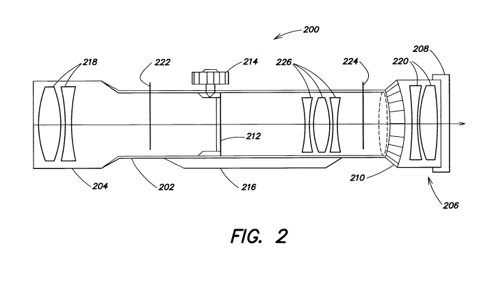
Referring now to FIG. 2, an example embodiment of a magnification zoom
sighting system according to the present disclosure is illustrated.
Magnification zoom
sighting system 200 includes an elongated tube housing 202 having an objective
end 204
and a distal ocular end 206. Magnification zoom sighting system 200 includes
an objective
lens group 218 mounted at the objective end 204 in a manner that faces the
target, and an
ocular lens group 220 mounted at the ocular end 206 in a manner that faces the
operator.
CA 02957447 2017-02-07
WO 2016/061659
PCT/CA2015/000537
6
The objective lens group 218 collects rays coming from the target and focuses
them at the
first focal plane 222 to create an image of the target. In varying
embodiments, the
objective lens group 218 may include a plurality of lenses. For example,
objective lens
group 218 may include a primary objective lens and a field lens to aid in
gathering light at
the first focal plane 222.
The zoom lens element 226 is located between the objective lens group 218 and
the ocular lens group 220. As discussed herein, the zoom lens element 226
reorients the
image in the second image plane 224 such that the image corresponds to the
target, i.e.,
top and bottom of the image are exactly as the eye perceives the top and
bottom of the
target. The ocular lens group 218 and the eyepiece 208 enable the operator to
view the
reoriented image of the target at the second image plane 224. In varying
embodiments, the
zoom lens element 226 may include one or more moveable optical elements. For
example,
the zoom lens element 226 may include a magnification lens or a focus lens to
visually
magnify or focus the image at the second image plane 224. Zoom lens element
226 may
further include any electro-optical, electromechanical, or mechanical system
to
manipulate one or more optical elements (e.g., a magnification lens) in the
zoom lens
clement 226. Alternatively, zoom lens element 226 may be coupled to a
processor that
controls the zoom lens element 226 to manipulate one or more optical elements.
In the example embodiment, the zoom lens element 226 further includes a
magnification adjustment mechanism 210 having an optical magnification setting
for
adjusting the optical magnification of the image. For example, the
magnification
adjustment mechanism 210 can include an engraved ring rotatably fixed about
the exterior
of the elongated tube housing 202. Manual rotation of the magnification
adjustment
mechanism 210 in a first direction drives a magnification lens in zoom lens
element 226
increasing the perceived size of the target. Manual rotation of the
magnification
adjustment mechanism 210 in the opposite direction retracts the magnification
lens and
decreases the perceived size of the target. In various embodiments, the
optical
magnification settings of the magnification adjustment mechanism 210 include
increments
of 6x, 8x, 10x, 12x, 15x, and 20x magnification. In other embodiments, the
optical
magnification settings of the magnification adjustment mechanism 210 include a
range of
5x to 20x magnification. It is noted that examples of specific implementations
are
provided here for illustrative purposes only and are not intended to be
limiting. The zoom
lens element 226 can include any mechanism known in the art of magnification
adjustment
CA 02957447 2017-02-07
WO 2016/061659
PCT/CA2015/000537
7
for varying the optical magnification of the zoom lens element 226 including,
for example,
electro-optical, electro-mechanical, or mechanical controllers to manipulate
one or more
optical elements (e.g., a magnification lens) in the zoom lens element 226.
Zooms lens
element 226 may also be coupled to a processor that determines an optical
magnification
setting and controls the zoom lens element 226 to provide an optical
magnification.
In the example embodiment, the magnification zoom sighting system 200 further
includes a reticle 212 disposed proximate the first image plane 222 such that
it is viewable
through the ocular lens group 220 and eyepiece 208 and superimposed upon the
image.
Reticle 212 can include cross-hairs, circles, horseshoes, dots, or any other
shape suited to
assist the operator in aiming the associated weapon. In various embodiments,
the reticle
212 is mobile and controllable through adjustment dials (e.g., adjustment dial
214) located
on the exterior of elongated tube housing 202. For example, magnification zoom
sighting
system 200 may have a top mounted elevation adjustment dial coupled with
reticle 212
that enables vertical reticle movement to compensate for elevation
discrepancies between
the operator and the target. In a further example, reticle 212 is coupled with
a side
mounted wind adjustment dial to compensate for effects of wind on projectile
accuracy.
Referring now to FIG. 3, with continuing reference to FIG. 2, in various
embodiments, the reticle 212 further includes magnification indicia 300 that
conveys the
optical magnification setting of the magnification adjustment mechanism 210.
For
example, the reticle 212 can convey 12x to the operator of the magnification
zoom
sighting system 200 when the corresponding optical magnification setting of
the
magnification adjustment mechanism 210 is 12x. FIG. 3 shows an example
embodiment
wherein the magnification indicia 300 includes a series of concentric arcs in
the upper
right quadrant of the field of view of the ocular lens group 220 and the
eyepiece 208. In
FIG. 3, the concentric arcs originate from a central aiming mark 302.
Corresponding to
each concentric arc is a numeric indicator that conveys the optical
magnification setting of
the magnification adjustment mechanism 210. In further embodiments, the
magnification
indicia 300 can include a series of hash marks, a series of lines, or a series
of angles, and
be disposed in an upper left, a lower left, a lower right, or any central
quadrant within the
field of view. The reticle 212 may also include a series of indicators
relating to the
estimation of wind speed, target speed, target size, distance, projection, or
ballistic
correction. As the operator activates the magnification adjustment mechanism
210 (e.g.,
rotates the engraved ring) to increase the magnification of the magnification
zoom sighting
CA 02957447 2017-02-07
WO 2016/061659
PCT/CA2015/000537
8
system 200, the target and the reticle 212 expand within the field of view of
the operator.
As the reticle 212 expands, the magnification indicia 300 expand and disappear
from the
field of view. A magnification indicium expanded to the edge of the field of
view indicates
the current magnification setting of the magnification adjustment mechanism
210.
For example, FIG. 4 illustrates a reticle 212 during a magnification setting
of lox.
Similarly, FIG. 5 illustrates a reticle 212 during a magnification setting of
20x. As the
magnification of the magnification zoom sighting system 200 is increased, the
magnification indicium for 6x, 8x, 10x, 12x, 15x, and any other
magnifications,
disappears from view. As a result, the operator sees the reticle 212 with the
magnification
indicium for 20x on the edge of his or her field of view. This indicates that
the current
magnification setting is 20x.
In various further embodiments, a reticle 212 having magnification indicia
300, as
described herein, may be used in binoculars, spotting scopes and other optical
sighting
devices. In particular, such devices may include devices used by a spotter of
a rifle team to
assist a shooter in aiming a weapon.
The magnification zoom sighting system 200 may further include a mounting
system 216. The mounting system 216 may include an orientation mechanism that
allows
for adjustment of the magnification zoom sighting system 200 relative to the
matter on
which it is mounted. The orientation mechanism may be used to "level" or
adjust the
magnification zoom sighting system 200 as necessary to correct orientation or
the field of
view of the system.
Having described above several aspects of at least one embodiment, it is to be
appreciated various alterations, modifications, and improvements will readily
occur to
those skilled in the art. Such alterations, modifications, and improvements
are intended to
be part of this disclosure and are intended to be within the scope of the
invention.
Accordingly, the foregoing description and drawings are by way of example
only, and the
scope of the invention should be determined from proper construction of the
appended
claims, and their equivalents.
What is claimed is: