Note: Descriptions are shown in the official language in which they were submitted.
CA 02957510 2017-02-07
DESCRIPTION
Title of Invention
ELECTRIC LEAKAGE PROTECTION DEVICE AND FEED CONTROL DEVICE
Technical Field
[0001] The present invention relates to electric leakage protection devices
and feed control
devices, and particularly to an electric leakage protection device for
detecting a leakage current
from a circuit and then protecting the circuit and a feed control device which
includes the
electric leakage protection device and is configured to control supply of
power to the circuit.
Background Art
[0002] In the past, there has been proposed a feed control device as disclosed
in Document 1
(JP 2013-128337 A). The feed control device disclosed in Document 1 includes a
controller
configured to close a relay interposed in a main circuit and control a self
leakage generator to
cause pseudo electric leakage in the main circuit in response to reception of
a state notification
signal indicative of allowance of charging from an electric vehicle (electric
automobile). In this
conventional example, operation check of an electric leakage detector is
conducted under such
a pseudo electric leakage state. When the electric leakage detector operates
properly to open the
relay as a result of the operation check, the controller closes the relay
again and starts charging
the electric vehicle.
[0003] In contrast, when the electric leakage detector does operate properly
as a result of the
operation check, the controller causes self electric leakage by the self
leakage generator after a
lapse of a predetermined time period, thereby conducting the operation check
of the electric
leakage detector again. Accordingly, the conventional example disclosed in
Document 1
conducts the operation check of the electric leakage detector again multiple
times in order to
reduce a possibility of false detection.
[0004] The electric leakage detector of the conventional example includes a
zero sequence
current transformer to measure unbalance between currents flowing through a
pair of power
-1-
CA 02957510 2017-02-07
supply paths constituting the main circuit. The electric leakage detector is
configured to
compare a secondary output of the zero sequence current transformer
corresponding to a
magnitude of the unbalance between currents, with a threshold value, and to
determine that
electric leakage has occurred when the secondary output exceeds the threshold
value.
[0005] Additionally, the self leakage generator of the conventional example
includes a series
circuit of a fixed resistor and a semiconductor switch, and the series circuit
is electrically
connected to the pair of power supply paths. Accordingly, the self leakage
generator makes a
short circuit between the pair of power supply paths by connecting them via
the fixed resistor
by turning on the semiconductor switch, and thereby cause unbalance between
currents flowing
through the pair of power supply paths, which leads to a pseudo electric
leakage state
(hereinafter, referred to as self electric leakage).
[0006] In a case of the self electric leakage caused by the self leakage
generator, a magnitude of
such an unbalance current flowing through the main circuit depends on a
difference between
electric potentials of the pair of power supply paths, which can be determined
by the power
supply voltage (effective value) of the AC power supply connected to the main
circuit and the
resistance of the fixed resistor of the self leakage generator.
[0007] Note that, the AC power supply has different power supply voltages
depending on
countries or regions (destinations), and may be classified into two major
systems: a 100 V
system and a 200 V system. In view of this, the self leakage generator of the
conventional
example is required to include a fixed resistor which is selected from the
fixed resistor with the
resistance corresponding to the power supply voltage of the 100 V system and
the fixed resistor
with the resistance corresponding to the power supply voltage of the 200 V
system in
accordance with a desired destination.
Summary of Invention
[0008] An object of the present invention would be to adapt to two or more
types of AC power
supplies having different effective values of a power supply voltage by use of
a common
structure.
-2-
CA 02957510 2017-02-07
[0009] The electric leakage protection device of one aspect according to the
present invention
includes an electric leakage detector, an electric leakage protector, and a
self leakage generator.
The electric leakage detector is configured to output an electric leakage
detection signal, when
a current leaked from a main circuit exceeds a threshold value. The electric
leakage protector is
configured to open a contact device interposed in the main circuit, when
receiving the electric
leakage detection signal. The self leakage generator includes; a first short
circuit having a first
electric resistance component and a first switch component electrically
connected in series with
each other, and a second short circuit having a second electric resistance
component and a
second switch component electrically connected in series with each other. The
first short circuit
and the second short circuit are electrically connected in parallel with each
other with regard to
a pair of power supply paths constituting the main circuit.
[0010] The feed control device of one aspect according to the present
invention includes: a
main circuit including a pair of power supply paths; a contact device
interposed in the main
circuit; and the electric leakage protection device of the above aspect for
protecting the main
circuit.
Brief Description of Drawings
[0011] FIG. 1 is a block diagram of a feed control device including an
electric leakage
protection device of one embodiment in accordance with the present invention.
FIG. 2 is a flow chart for illustrating operation of the electric leakage
protection device.
FIG. 3 is a partial flow chart for illustrating operation of the electric
leakage protection
device.
Description of Embodiments
[0012] The following description referring to FIG. 1 and FIG. 2 is made to a
feed control
device 1 including an electric leakage protection device of one embodiment
according to the
present invention. However, the electric leakage protection device according
to the present
invention may be provided to a device other than such a feed control devices.
[0013] The feed control device 1 is used to form power supply paths from an
external power
-3-
CA 02957510 2017-02-07
supply such as a commercial AC power supply to a battery 102 included in an
electric vehicle
100 and to control supply of power to the battery 102.
[0014] The electric vehicle 100 includes the battery 102 which may be a
secondary battery such
as a lithium ion battery. Further, the electric vehicle 100 includes a
charging circuit 103
configured to receive power from the external power supply via a charging
inlet 101 and then
charge the battery 102. The electric vehicle 100 is configured to run by
driving motors with
power stored in the battery 102. The electric vehicle 100 may be an electric
automobile, a
plug-in hybrid vehicle, or a fuel cell vehicle, for example.
[0015] As shown in FIG. 1, the feed control device 1 includes a line (live
line) Li serving as a
conduction path for a live conductor (L phase), a line (neutral line) L2
serving as a conduction
path for a neutral conductor (N phase), and a line (ground line) L3 serving as
a conduction path
for a ground conductor, between the external power supply (the commercial AC
power supply)
and the electric vehicle 100. Note that, the live line (first power supply
path) Li and the neutral
line (second power supply path) L2 constitute a pair of power supply paths
(main circuit).
[0016] There is a power supply side plug (first plug) P1 electrically
connected to first ends of
the lines Li to L3. This power supply side plug P1 is electrically connected,
in a removable
manner, to an outlet (for example, an electrical socket) electrically
connected to the external
power supply. Additionally, there is a vehicle side plug (second plug) P2
electrically connected
to second ends of the lines Li to L3. This vehicle side plug P2 is
electrically connected, in a
removable manner, to the charging inlet 101 of the electric vehicle 100.
[0017] The feed control device 1 includes the electric leakage protection
device, the main
circuit (the live line Li and the neutral line L2) protected by the electric
leakage protection
device, a contact device (the relay RY1) provided to the main circuit, a relay
driver 25 for
opening and closing the contact device, and the controller 20.
[0018] The relay RY1 includes a pair of relay contacts individually interposed
in the live line
Li and the neutral line L2. The relay RY1 is controlled to close the relay
contacts (that is, the
relay RY1 is turned on), which allows supply of power from the power supply
side plug P1 to
-4-
CA 02957510 2017-02-07
the vehicle side plug P2.
[0019] The controller 20 may be realized by a microcontroller (hereinafter,
abbreviated to
"micro"), for example. The controller 20 is configured to perform entire
control of the electric
leakage protection device and the feed control device 1. Accordingly, the
controller 20 acts as a
controller (electric leakage controller) 200 of the electric leakage
protection device. However,
the controller (electric leakage controller) 200 configured to perform entire
control of the
electric leakage protection device may be realized by hardware (for example, a
micro)
independent from the controller 20 of the feed control device 1.
[0020] Additionally, the feed control device 1 includes a feeding detector 21,
an L line
voltmeter 23, an N line voltmeter 24, a signal receiver 26, a signal
transmitter 27, a conduction
indication lamp LP1, and an error indication lamp LP2. Note that, the feeding
detector 21, the
L line voltmeter 23, the N line voltmeter 24, the signal receiver 26, the
signal transmitter 27,
the conduction indication lamp LP1, and the error indication lamp LP2 are
optional.
[0021] The feeding detector 21 is configured to determine whether power is
supplied from the
external power supply, by detecting zero crossing of a voltage (potential
difference) between
parts of the live line Li and the neutral line L2 between the relay RY1 and
the power supply
side plug Pl. When the feeding detector 21 determines that power has been
supplied from the
external power supply, the controller 20 may turn on the conduction indication
lamp LP1.
[0022] Note that, the feeding detector 21 of the present embodiment is
configured to determine
whether the external power supply is a 100 V system or a 200 V system based on
a peak value
of the voltage, and then output a result of determination to the controller
20. In other words, the
feeding detector 21 serves as a voltmeter configured to measure a voltage
applied between the
pair of the power supply paths Li and L2. The voltmeter is configured to
determine whether
the voltage measured by the voltmeter corresponds to a first power supply
voltage or a second
power supply voltage higher than the first power supply voltage and then
output a result of
determination to the controller 20. The first power supply voltage is a
voltage corresponding to
the external power supply (AC power supply) of the 100 V system, and the
second power
supply voltage is a voltage corresponding to the external power supply (AC
power supply) of
-5-
CA 02957510 2017-02-07
the 200 V system. Note that, the feeding detector 21 is not necessarily
configured to act as the
voltmeter.
[0023] The L line voltmeter 23 is configured to determine whether a voltage of
the live line Li
(a potential difference between the live line Li and the ground line L3)
between the relay RY1
and the vehicle side plug P2 (a secondary side of the relay RY1) is not
smaller than a
predetermined threshold value. The N line voltmeter 24 is configured to
determine whether a
voltage of the neutral line L2 (a potential difference between the neutral
line L2 and the ground
line L3) between the relay RY1 and the vehicle side plug P2 (the secondary
side of the relay
RY1) is not lower than the predetermined threshold value.
[0024] The controller 20 is configured to determine that welding of the
contact device (the
relay contacts) has occurred, when at least one of the L line voltmeter 23 and
the N line
voltmeter detects a voltage equal to or larger than the threshold value while
the contact device
(the relay RY1) is opened (turned off). It is preferable that the controller
20 turn on the error
indication lamp LP2 when determining that welding of the contact device has
occurred.
[0025] The relay driver 25 is configured to control the relay RY1 according to
a control signal
inputted from the controller 20 to thereby close (turn on) and open (turn off)
the relay contacts.
[0026] The signal receiver 26 is electrically connected to the electric
vehicle 100 via a
conduction path (hereinafter referred to as "signal line") L4 which is
provided in addition to the
conduction paths Li to L3. The signal receiver 26 is configured to receive a
control pilot signal
(CPLT signal) transmitted through the signal line L4 from the electric vehicle
100 and output
.. the received CPLT signal to an input port P15 of the controller 20.
[0027] The signal transmitter 27 is configured to convert a transmission
signal outputted from
the output port P02 of the controller 20 into the CPLT signal and then
transmit it to the electric
vehicle 100. Note that, the CPLT signal is well known as disclosed in Document
1, and
therefore detailed description thereof is omitted.
[0028] Note that, the controller 20 is configured to turn on the error
indication lamp LP2 to
-6-
CA 02957510 2017-02-07
make announcement when an electric leakage detector 22 which is described
below has
detected electric leakage or when abnormality (for example, welding) of the
relay RY1 has
been detected.
.. [0029] The electric leakage protection device includes the electric leakage
detector 22, an
electric leakage protector (a relay driver) 25, and a self leakage generator
28. Further, in the
present embodiment, the electric leakage protection device includes the
electric leakage
controller 200, the voltmeter (the feeding detector 21), and the error
indication lamp LP2.
1() [0030] The electric leakage detector 22 is configured to output an
electric leakage detection
signal when a leakage current flowing from the main circuit (that is, a
current leaked from the
main circuit) exceeds a threshold value. For example, the electric leakage
detector 22 includes a
zero sequence current transformer 220 and is configured to output the electric
leakage detection
signal when an output voltage of the zero sequence current transformer 220
proportional to the
leakage current flowing from the main circuit exceeds a threshold value.
[0031] The zero sequence current transformer 220 has the live line Li and the
neutral line L2
inserted through a core 221 with a circular ring shape and is configured to
output, from an
output line (secondary winding) 222, a voltage proportional to unbalance
between currents
flowing through the live line Li and the neutral line L2. Note that, the
electric leakage
detection signal outputted from the electric leakage detector 22 is inputted
into an input port
PH of the controller 20 and the relay driver 25. The zero sequence current
transformer 220 is
positioned in relation to the pair of power supply paths Li and L2 so as to be
between a
connection point between one of the pair of power supply paths Li and L2 and
the self leakage
generator 28 and the other of the pair of power supply paths Li and L2 and the
self leakage
generator 28. In FIG. 1, the self leakage generator 28 is connected to the
first line Li at a point
closer to the first plug P1 than the zero sequence current transformer 220 is.
Further, the self
leakage generator 28 is connected to the second line L2 at a point closer to
the second plug P2
than the zero sequence current transformer 220 is.
[0032] When receiving the electric leakage detection signal, the relay driver
25 operates the
relay RY1 to open (turn off) the relay contacts. As understood from the above,
the relay driver
-7-
CA 02957510 2017-02-07
25 functions as the electric leakage protector configured to open the contact
device interposed
in the main circuit when receiving the electric leakage detection signal.
Accordingly, in the
present embodiment, the relay driver 25 acts as the electric leakage
protector.
[0033] The self leakage generator 28 includes a first short circuit having a
first electric
resistance component 280 and a first switch component 281 electrically
connected in series
with each other, and a second short circuit having a second electric
resistance component 282
and a second switch component 283 electrically connected in series with each
other. In other
words, the first short circuit is a series circuit of the first electric
resistance component 280 and
the first switch component 281, and the second short circuit is a series
circuit of the second
electric resistance component 282 and the second switch component 283.
[0034] The first electric resistance component 280 and the second electric
resistance
component 282 each may be a single resistor or a series circuit of two or more
resistors. An
electric resistance of the first electric resistance component 280 may be
equal to an electric
resistance of the second electric resistance component 282. Note that, it is
preferable that the
electric resistance (resistance) of the first electric resistance component
280 be smaller than the
electric resistance (resistance) of the second electric resistance component
282.
[0035] The first switch component 281 and the second switch component 283 each
may be an
opto-isolated SSR (short for a solid state relay), for example. The first
switch component 281 is
turned on and off according to the control signal outputted from an output
port PO4 of the
controller 20. Similarly, the second switch component 283 is turned on and off
according to the
control signal outputted from an output port P05 of the controller 20. Note
that, the
.. aforementioned opto-isolated SSR is well-known and therefore detailed
description of
configuration and operation thereof is omitted. However, the first switch
component 281 and
the second switch component 283 each may not be limited to such an opto-
isolated SSR.
[0036]The electric leakage controller 200 controls the self leakage generator
28. In more detail,
the electric leakage controller 200 is configured to perform any one of a
first process and a
second process in accordance with a voltage measured by the voltmeter (the
feeding detector)
21.
-8-
CA 02957510 2017-02-07
[0037] The first process is defined as a process of turning on the first
switch component 281
while turning off the second switch component 283. The second process is
defined as a process
of turning on the second switch component 283 while turning off the first
switch component
281. The electric leakage controller 200 is configured to perform the first
process when the
voltage measured by the voltmeter (the feeding detector) 21 corresponds to the
first power
supply voltage. The electric leakage controller 200 is configured to perform
the second process
when the voltage measured by the voltmeter 21 corresponds to the second power
supply voltage.
In summary, the first process corresponds to the first power supply voltage,
and the second
process corresponds to the second power supply voltage.
[0038] The first short circuit is configured to cause a short circuit between
the live line Li and
the neutral line L2 by interconnecting them through the first electric
resistance component 280
when the controller 20 turns on the first switch component 281. When the first
short circuit
causes a short circuit between the live line Li and the neutral line L2, the
leakage current
(hereinafter referred to as a self leakage current) which depends on the
electric resistance of the
first electric resistance component 280 and the power supply voltage flows
through the first
short circuit. For example, when the external power supply has the power
supply voltage
(effective value) of 120 V, the self leakage current equal to or smaller than
7.5 mA flows
provided that the first electric resistance component 280 has the resistance
equal to or larger
than 16 ka
[0039] The second short circuit is configured to cause a short circuit between
the live line Ll
and the neutral line L2 by interconnecting them through the second electric
resistance
component 282 when the controller 20 turns on the second switch component 283.
When the
second short circuit causes a short circuit between the live line Li and the
neutral line L2, the
leakage current (self leakage current) which depends on the electric
resistance of the second
electric resistance component 282 and the power supply voltage flows through
the second short
circuit. For example, when the external power supply has the power supply
voltage (effective
value) of 240 V, the self leakage current equal to or smaller than 7.5 mA
flows provided that
the second electric resistance component 282 has the resistance equal to or
larger than 32 ka
-9-
CA 02957510 2017-02-07
[0040] The resistance of the self leakage generator 28 for the first process
and the resistance of
the self leakage generator 28 for the second process are selected so as to
cause a flow of a self
leakage current equal to or smaller than a prescribed value (7.5 mA), for
example. Note that,
the prescribed value is selected appropriately in consideration of environment
where the electric
leakage protection device is supposed to be used.
[0041] The controller 20 determines that a self leakage test has been passed,
when the electric
leakage detection signal is inputted into the input port P11 under as
situation where the self
leakage generator 28 causes a self leakage (causes a flow of the self leakage
current). In
contrast, the controller 20 determines that the self leakage test has not been
passed, when the
electric leakage detection signal is not inputted into the input port P11
under the above situation.
In addition, the controller 20 turns on the error indication lamp LP2 when
determining that the
self leakage test has not been passed.
[0042] As apparent from the above, the electric leakage controller 200 is
configured to conduct
the self leakage test. The electric leakage controller configured to, in the
self leakage test,
determine that the self leakage test has not been passed, when failing to
receive the electric
leakage detection signal within a predetermined time period from time of
performing either the
first process or the second process in response to the voltage measured by the
voltmeter (the
feeding detector) 21. The electric leakage controller 200 is configured to
light the error
indication lamp LP2, when determining that the self leakage test has not been
passed.
[0043] Next, operation of the feed control device 1 of the present embodiment
is described with
reference to a flow chart of FIG. 2. Note that, in an initial state, each of
the first switch
component 281 and the second switch component 283 of the self leakage
generator 28 is off.
[0044] When the power supply side plug P1 is connected to the inlet of the
external power
supply, AC power supply is supplied from the external power supply to the feed
control device
1 and thus the feed control device 1 starts to operate (step Si). While the
vehicle side plug P2 is
not connected to the charging inlet of the electric vehicle 100, the
controller 20 determines that
the vehicle side plug P2 has not been connected to the electric vehicle 100
yet, based on the
CPLT signal received by the signal receiver 26. Note that, the controller 20
keeps the relay
-10-
CA 02957510 2017-02-07
RY1 off providing that the vehicle side plug P2 is not connected to the
electric vehicle 100.
[0045] The controller 20 determines whether the power supply voltage measured
by the feeding
detector 21 corresponds to the 100 V system (step S2). If the power supply
voltage corresponds
to the 100 V system (step S2; yes), the controller 20 outputs the control
signal from the output
port PO4, thereby turning on the first switch component 281 (step S3). In
contrast, if the power
supply voltage measured by the feeding detector 21 corresponds to the 200 V
system (step S2;
no), the controller 20 outputs the control signal from the output port P05,
thereby turning on
the second switch component 283 (step S4). Note that, the controller 20 may
store a result of
determination with regard to the power supply voltage in a built-in memory,
for example.
[0046] When the first switch component 281 or the second switch component 283
is turned on,
the self leakage current flows from the main circuit, and thus self leakage
occurs. In this regard,
the controller 20 selects the resistance (from the resistances of the first
electric resistance
component 280 and the second electric resistance component 282) for a path of
short circuiting
the main circuit, in accordance with the power supply voltage of the external
power supply. In
more detail, the controller 20 selects the first electric resistance component
280 with a
relatively small resistance when the power supply voltage corresponds to the
100 V system, and
selects the second electric resistance component 282 with a relatively large
resistance when the
power supply voltage corresponds to the 200 V system. Accordingly, one of the
two electric
resistance components 280 and 282 is selected in accordance with the power
supply voltage.
Therefore, almost the same self leakage current can flow from the main circuit
in one case
where the power supply voltage corresponds to the 100 V system and the other
case where the
power supply voltage corresponds to the 200 V system.
[0047] Providing that the electric leakage detector 22 operates properly, it
detects the self
leakage and then outputs the electric leakage detection signal. The controller
20 determines that
the self leakage test has been passed, providing that the electric leakage
detection signal is
inputted into the input port PI1 within the predetermined time period (for
example, a few
seconds to more than ten but less than twenty seconds) from time of turning on
the first switch
component 281 or the second switch component 283, and determines that the self
leakage test
has not been passed, providing that the electric leakage detection signal is
inputted into the
-11-
CA 02957510 2017-02-07
input port P11 within the predetermined time period from that time (step S5).
When the self
leakage test is determined to have not been passed, the controller 20 lights
the error indication
lamp LP2 to conduct error indication (step S15). Note that, after a lapse of
the predetermined
time period, the controller 20 turns off the switch component (the first
switch component 281 or
the second switch component 283) which has been turned on at step S3 or step
S4.
[0048] When the self leakage test is determined to have been passed, the
controller 20 waits
until the vehicle side plug P2 is electrically connected to the charging inlet
of the electric
vehicle 100 (step S6). When receiving, by the signal receiver 26, the CPLT
signal indicating
that the vehicle side plug P2 has been electrically connected to the charging
inlet (step S6; yes),
the controller 20 instructs the self leakage generator 28 to cause self
leakage again (step S7). In
this regard, the controller 20 conducts the self leakage test by turning on
the switch component
(the first switch component 281 or the second switch component 283)
corresponding to the
result of the determination with regard to the power supply voltage stored in
the built-in
memory.
[0049] Note that, there may be a probability that the feed control device 1 of
the present
embodiment is left in a state where the power supply side plug P1 is still
electrically connected
to the inlet of the external power supply. In such a case, a step of
connecting the power supply
side plug P1 to the inlet may be omitted from the charging process, and thus
the charging
process may start from a step of electrically connecting the vehicle side plug
P2 to the charging
inlet 101 of the electric vehicle 100. In this case, the controller 20 starts
the process from step
S6. Accordingly, the controller 20 conducts the self leakage test even if the
vehicle side plug P2
is electrically connected to the charging inlet. Thereby, it is possible to
certainly confirm that
the electric leakage detector 22 can operate properly, before charging the
electric vehicle 100.
[0050] When the self leakage test is determined to have been passed (step S8;
yes), the
controller 20 waits until the signal receiver 26 receives from the electric
vehicle 100 the CPLT
signal indicative of permission of charging (step S8). In contrast, when the
self leakage test is
determined to have not been passed, the controller 20 lights the error
indication lamp LP2 to
conduct error indication (step S15). Note that, after a lapse of the
predetermined time period,
the controller 20 turns off the switch component (the first switch component
281 or the second
-12-
CA 02957510 2017-02-07
switch component 283) which has been turned on at step S7.
[0051] When receiving by the signal receiver 26 the CPLT signal indicative of
permission of
charging (step S9; yes), the controller 20 outputs the control signal from the
output port P01 to
control the relay driver 25 to turn on the relay RY1 (step S10). Thereafter,
the controller 20
instructs the self leakage generator 28 to cause self leakage again to conduct
the self leakage
test. In this regard, the controller 20 conducts the self leakage test by
turning on the switch
component (the first switch component 281 or the second switch component 283)
corresponding to the result of the determination with regard to the power
supply voltage stored
in the built-in memory. When the self leakage test is determined to have not
been passed, the
controller 20 lights the error indication lamp LP2 to conduct error indication
(step S15). Note
that, after a lapse of the predetermined time period, the controller 20 turns
off the switch
component (the first switch component 281 or the second switch component 283)
which has
been turned on at step S10.
[0052] Note that, the charging circuit 103 of the electric vehicle 100 may
conduct timer-based
operation. In such timer-based operation, the charging circuit 103 starts
charging at designated
start time by transmitting the CPLT signal indicative of permission of
charging, and ends the
charging at designated finish time by transmitting the CPLT signal indicative
stop of charging.
When the charging circuit 103 of the electric vehicle 100 conducts the timer-
based operation, in
some cases the controller 20 may result in waiting the CPLT signal indicating
permission of
charging from the electric vehicle 100 for several hours to more than ten but
less than twenty
hours. In this case, abnormality may occur in the electric leakage detector 22
while waiting for
the signal. Accordingly, the controller 20 conducts the self leakage test even
if receiving by the
signal receiver 26 the CPLT signal indicative of permission of charging.
Thereby, it is possible
to certainly confirm that the electric leakage detector 22 can operate
properly, before charging
the electric vehicle 100.
[0053] When the electric leakage detector 22 operates properly, it detects
self electric leakage
and outputs the electric leakage detection signal to the controller 20.
Therefore, the controller
20 determines that the self leakage test has been passed when the electric
leakage detection
signal is inputted into the input port PI1 (step Si!; yes). Further, when
detecting self electric
-13-
CA 02957510 2017-02-07
leakage, the electric leakage detector 22 operates the relay driver 25 to turn
off the relay RY1
(step S12). Both the voltages of the live line Li and the neutral line L2
become zero on a
secondary side of the relay RY1 providing that the relay contacts of the relay
RY1 are not
welded. The controller 20 determines whether the relay contacts have been
welded, based on
measurement results of the L line voltmeter 23 and the N line voltmeter 24
(S13). In more
detail, when a voltage equal to or larger than the threshold value is
developed on the secondary
side of the relay RY1, the controller 20 determines that the relay contacts
have been welded
and then turns on the error indication lamp LP2 (step S15). In contrast, when
the voltage
developed on the secondary side of the relay RY1 is smaller than the threshold
value, the
controller 20 determines that the relay contacts have not been welded (that
is, opened) and then
controls the relay driver 25 to turn on the relay RY1 (step S14). Note that,
it is preferable that
the controller 20 differentiate between patterns of lighting the error
indication lamp LP2 for a
case where the self leakage test has not been passed and another case where
the relay contacts
are determined to have been welded.
[0054] Note that, when both the first switch component 281 and the second
switch component
283 are turned on, a parallel circuit of the first electric resistance
component 280 and the
second electric resistance component 282 is electrically connected between the
live line Li and
the neutral line L2. In this case, a combined resistance of the parallel
circuit is smaller than the
resistance of the first electric resistance component 280 and the resistance
and the second
electric resistance component 282. Therefore, when the power supply voltage
corresponds to
the 200 V system, both the first switch component 281 and the second switch
component 283
are turned on. In contrast, when the power supply voltage corresponds to the
100 V system,
either the first switch component 281 or the second switch component 283 may
be turned on. In
this case, the first electric resistance component 280 and the second electric
resistance
component 282 may have the same resistance.
[0055] In other words, in a case where the resistance of the first electric
resistance component
280 and the resistance of the second electric resistance component 282 are
equal to each other,
the first process may be defined as a process of turning on both the first
switch component 281
and the second switch component 283, and the second process may be defined as
a process of
turning on the second switch component 283 while turning off the first switch
component 281.
-14-
CA 02957510 2017-02-07
[0056] The feeding detector 21 is not necessarily configured to act as the
voltmeter (in other
words, the electric leakage protection device may not include the voltmeter).
In such a case, the
electric leakage controller 200 performs a determining process of determining
the power supply
voltage applied to the main circuit. In the determining process, the electric
leakage controller
200 determines that the power supply voltage of the power supply connected to
the main circuit
is the first power supply voltage when succeeding in receiving the electric
leakage detection
signal within a predetermined time period from time of performing the first
process but failing
to receive the electric leakage detection signal within the predetermined time
period from time
of performing the second process. In the determining process, the electric
leakage controller
200 determines that the power supply voltage of the power supply connected to
the main circuit
is the second power supply voltage when succeeding in receiving the electric
leakage detection
signal within the predetermined time period from time of performing the first
process and also
succeeding in receiving the electric leakage detection signal within the
predetermined time
period from time of performing the second process. The electric leakage
controller 200
determines that the self leakage test has not been passed, when failing to
receive the electric
leakage detection signal within the predetermined time period from time of
performing either
the first process or the second process in accordance with a result of the
determining process. In
summary, in a case where the result of the determining process indicates that
the power supply
voltage is the first power supply voltage, the electric leakage controller 200
performs the first
process in the self leakage test. The electric leakage controller 200
determines that the self
leakage test has not been passed providing that the electric leakage detection
signal is obtained
within the predetermined time period from time of performing the first
process. In contrast, in a
case where the result of the determining process indicates that the power
supply voltage is the
second power supply voltage, the electric leakage controller 200 performs the
second process in
the self leakage test. The electric leakage controller 200 determines that the
self leakage test has
not been passed providing that the electric leakage detection signal is
obtained within the
predetermined time period from time of performing the second process.
[0057] For example, as shown in the flow chart of FIG. 3, the feed control
device 1 starts
operating (step SS1) when the power supply side plug P1 is connected to the
inlet of the
external power supply and then the external power supply supplies AC power to
the feed
-15-
CA 02957510 2017-02-07
control device 1. Accordingly, the controller 20 turns on the first switch
component 281 and the
second switch component 283 (step SS2).
[0058] When the first switch component 281 and the second switch component 283
are turned
on, the self leakage current flows from the main circuit, which results in
self electric leakage.
The electric leakage detector 22 detects the self electric leakage and then
outputs the electric
leakage detection signal, providing that it operates properly. The controller
20 determines that
the self leakage test has been passed when the electric leakage detection
signal is inputted into
the input port PI1 within the predetermined time period, or the controller 20
determines that the
self leakage test has not been passed when the electric leakage detection
signal is not inputted
into the input port PI1 within the predetermined time period (step SS3). When
the self leakage
test is determined to have not been passed, the controller 20 turns on the
error indication lamp
LP2 to conduct error indication (step SS8).
[0059] When the self leakage test is determined to have been passed, the
controller 20 turns off
the first switch component 281 and on the second switch component 283 (step
SS4). When the
electric leakage detector 22 operates properly and the power supply voltage
corresponds to the
200 V system, the electric leakage detector 22 detects the self electric
leakage based on the self
leakage current flowing through the second short circuit and outputs the
electric leakage
detection signal. The controller 20 determines that the power supply voltage
corresponds to the
200 V system when the electric leakage detection signal is inputted within the
predetermined
time period (step SS6). In contrast, when the power supply voltage corresponds
to the 100 V
system, the self leakage current flowing through the second short circuit is
relatively small.
Consequently, the electric leakage detector 22 fails to detect self electric
leakage and does not
output the electric leakage detection signal. For this reason, the controller
20 determines that
the power supply voltage corresponds to the 100 V system, providing that the
electric leakage
detection signal is not inputted within the predetermined time period (step
SS7). The controller
20 stores the result of determination with regard to the power supply voltage
in its built-in
memory, and performs the steps following step S6 in FIG. 2. Note that, with
regard to the steps
following step S6 in FIG. 2, it is preferable that the controller 20 turn on
the first switch
component 281 and the second switch component 283 to cause self electric
leakage when the
power supply voltage corresponds to the 100 V system. Optionally, with regard
to the steps
-16-
CA 02957510 2017-02-07
following step S6 in FIG. 2, it is preferable that the controller 20 turn on
the second switch
component 283 only to cause self electric leakage when the power supply
voltage corresponds
to the 200 V system. Note that, description of the steps following step S6 in
FIG. 2 is omitted
to avoid redundancy.
[0060] As described above, the electric leakage protection device of the
present embodiment
includes the electric leakage detector 22, the electric leakage protector (the
relay driver 25), and
the self leakage generator 28. The electric leakage detector 22 is configured
to output the
electric leakage detection signal, when the current leaked from the main
circuit exceeds the
threshold value. The electric leakage protector (the relay driver 25) is
configured to open the
contact device (the relay RY1) interposed in the main circuit, when receiving
the electric
leakage detection signal. The self leakage generator 28 includes the first
short circuit having the
first electric resistance component 280 and the first switch component 281
electrically
connected in series with each other, and the second short circuit having the
second electric
resistance component 282 and the second switch component 283 electrically
connected in series
with each other. The first short circuit and the second short circuit are
electrically connected in
parallel with each other with regard to the pair of power supply paths (the
live line Li and the
neutral line L2) constituting the main circuit.
[0061] Further, the feed control device 1 of the present embodiment includes
the electric
leakage protection device, the main circuit protected by the electric leakage
protection device,
and the controller 20 for opening and closing the contact device provided to
the main circuit.
[0062] The electric leakage protection device (the feed control device 1) of
the present
embodiment is configured as above, and thereby, in contrast to the
conventional example, can
be adapted to two or more types of AC power supplies having different
effective values of a
power supply voltage by use of a common structure.
[0063] Additionally, in the electric leakage protection device (the feed
control device 1) of the
present embodiment, it is preferable that the resistance of the first electric
resistance component
280 and the resistance of the second electric resistance component 282 be
different from each
other.
-17-
CA 02957510 2017-02-07
[0064] Further, it is preferable that the electric leakage protection device
(the feed control
device 1) of the present embodiment include the voltmeter (the feeding
detector 21) configured
to measure a voltage applied to the main circuit. Furthermore, it is
preferable that the self
.. leakage generator 28 be configured to turn on either the first switch
component 281 or the
second switch component 283 in accordance with the voltage measured by the
voltmeter (the
feeding detector 21).
[0065] As described above, the electric leakage protection device of the first
aspect in
accordance with the present invention includes an electric leakage detector
(22), an electric
leakage protector (25), and a self leakage generator (28). The electric
leakage detector (22) is
configured to output an electric leakage detection signal, when a current
leaked from a main
circuit exceeds a threshold value. The electric leakage protector (25) is
configured to open a
contact device (RY1) interposed in the main circuit, when receiving the
electric leakage
detection signal. The self leakage generator (28) includes a first short
circuit having a first
electric resistance component (280) and a first switch component (281)
electrically connected
in series with each other, and a second short circuit having a second electric
resistance
component (282) and a second switch component (283) electrically connected in
series with
each other. The first short circuit and the second short circuit are
electrically connected in
parallel with each other with regard to a pair of power supply paths (L1 and
L2) constituting
the main circuit.
[0066] In the electric leakage protection device of the second aspect which
would be realized in
combination with the first aspect, the self leakage generator (28) is
connected between the pair
of power supply paths (L1 and L2).
[0067] In the electric leakage protection device of the third aspect which
would be realized in
combination with the first or second aspect, the electric leakage detector
(22) is configured to
measure a current leaked from the main circuit based on an output voltage of a
zero sequence
current transformer (220). The zero sequence current transformer (220) is
positioned in relation
to the pair of power supply paths (L1 and L2) so as to be between a connection
point between
one of the pair of power supply paths (L1 and L2) and the self leakage
generator (28) and the
-18-
CA 02957510 2017-02-07
[0068] In the electric leakage protection device of the fourth aspect which
would be realized in
combination with any one of the fifth to third aspects, the electric leakage
protection device
further includes: a voltmeter (21) configured to measure a voltage applied
across the main
circuit; and a controller (200) configured to control the self leakage
generator (28). The
controller (200) is configured to perform any one of a first process and a
second process in
accordance with the voltage measured by the voltmeter (21). The first process
is defined as a
process of turning on the first switch component (281) while turning off the
second switch
component (283), or another process of turning on both the first switch
component (281) and the
second switch component (283). The second process is defined as a process of
turning on the
second switch component while turning off the first switch component (281).
[0069] In the electric leakage protection device of the fifth aspect which
would be realized in
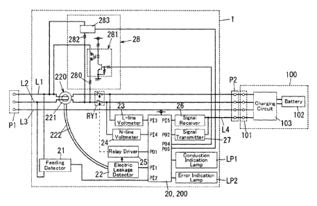
combination with the fourth aspect, a resistance of the first electric
resistance component (280)
and a resistance of the second electric resistance component (282) are
different from each other.
[0070] In the electric leakage protection device of the sixth aspect which
would be realized in
combination with the fifth aspect, the resistance of the first electric
resistance component (280)
is smaller than the resistance of the second electric resistance component
(282). The controller
(200) is configured to perform the first process, when the voltage measured by
the voltmeter
(21) corresponds to a first power supply voltage. The controller (200) is
configured to perform
the second process, when the voltage measured by the voltmeter (21)
corresponds to a second
power supply voltage higher than the first power supply voltage.
[0071] In the electric leakage protection device of the seventh aspect which
would be realized in
combination with the fourth aspect, a resistance of the first electric
resistance component (280) and a
resistance of the second electric resistance component (282) are equal to each
other. The controller
(200) is configured to perform the first process, when the voltage measured by
the voltmeter (21)
corresponds to a first power supply voltage. The controller (200) is
configured to perform the
second process, when the voltage measured by the voltmeter (21) corresponds to
a second power
supply voltage higher than the first power supply voltage. The first process
is defmed as a process
of turning on both the first switch component (281) and the second switch
component (283).
-19-
CA 02957510 2017-02-07
second process is defined as a process of turning on both the first switch
component (281) and
the second switch component (283).
[0072] In the electric leakage protection device of the eighth aspect which
would be realized in
combination with any one of the fourth to seventh aspects, the controller
(200) is configured to
determine that a self leakage test has not been passed, when failing to
receive the electric
leakage detection signal within a predetermined time period from time of
performing either the
first process or the second process in response to the voltage measured by the
voltmeter (21).
.. [0073] In the electric leakage protection device of the ninth aspect which
would be realized in
combination with the eighth aspect, the electric leakage protection device
further includes an
error indication lamp. The controller (200) is configured to light the error
indication lamp,
when determining that the self leakage test has not been passed.
.. [0074] The electric leakage protection device of the tenth aspect would be
realized in
combination with any one of the first to third aspects and further includes a
controller (200)
configured to control the self leakage generator (28). The controller (200) is
configured to
perform a first process corresponding to a first power supply voltage and a
second process
corresponding to a second power supply voltage higher than the first power
supply voltage. A
resistance of the first electric resistance component (280) is smaller than a
resistance of the
second electric resistance component (282). The first process is defined as a
process of turning
on the first switch component (281) while turning off the second switch
component (283), or
another process of turning on both the first switch component (281) and the
second switch
component (283). The second process is defined as a process of turning on the
second switch
component while turning off the first switch component (281). The controller
(200) is
configured to perform a determining process of determining a power supply
voltage of a power
supply connected to the main circuit. The controller (200) is configured to,
in the determining
process, determine that the power supply voltage is the first power supply
voltage when
succeeding in receiving the electric leakage detection signal within a
predetermined time period
from time of performing the first process but failing to receive the electric
leakage detection
signal within the predetermined time period from time of performing the second
process, and
determine that the power supply voltage is the second power supply voltage
when succeeding
-20-
CA 02957510 2017-02-07
in receiving the electric leakage detection signal within the predetermined
time period from
time of performing the first process and also succeeding in receiving the
electric leakage
detection signal within the predetermined time period from time of performing
the second
process. The controller (200) is configured to determine that a self leakage
test has not been
passed, when failing to receive the electric leakage detection signal within
the predetermined
time period from time of performing either the first process or the second
process in accordance
with a result of the determining process.
[0075] The electric leakage protection device of the eleventh aspect would be
realized in
0 combination with any one of the first to third aspects and further
includes a controller (200)
configured to control the self leakage generator (28). The controller (200) is
configured to
perform a first process corresponding to a first power supply voltage and a
second process
corresponding to a second power supply voltage higher than the first power
supply voltage. A
resistance of the first electric resistance component (280) is equal to a
resistance of the second
electric resistance component (282). The first process is defined as a process
of turning on both
the first switch component (281) and the second switch component (283). The
second process is
defined as a process of turning on the second switch component (283) while
turning off the first
switch component (281). The controller (200) is configured to perform a
determining process of
determining a power supply voltage of a power supply connected to the main
circuit. The
controller (200) is configured to, in the determining process, determine that
the power supply
voltage is the first power supply voltage when succeeding in receiving the
electric leakage
detection signal within a predetermined time period from time of performing
the first process
but failing to receive the electric leakage detection signal within the
predetermined time period
from time of performing the second process, and determine that the power
supply voltage is the
second power supply voltage when succeeding in receiving the electric leakage
detection signal
within the predetermined time period from time of performing the first process
and also
succeeding in receiving the electric leakage detection signal within the
predetermined time
period from time of performing the second process. The controller (200) is
configured to
determine that a self leakage test has not been passed, when failing to
receive the electric
leakage detection signal within the predetermined time period from time of
performing either
the first process or the second process in accordance with a result of the
determining process.
-21-
CA 02957510 2017-02-07
[0076] The feed control device of the twelfth aspect in accordance with the
present invention
includes: a main circuit including a pair of power supply paths (L1 and L2); a
contact device
(RY1) interposed in the main circuit; and the electric leakage protection
device of any one of
the first to eleventh aspects for protecting the main circuit.
[0077] The electric leakage protection device and the feed control device of
aspects according
to the present invention can be adapted to two or more types of AC power
supplies having
different effective values of a power supply voltage by use of a common
structure.
-22-