Note: Descriptions are shown in the official language in which they were submitted.
CA 02957524 2017-02-09
- 1 -
TILING LAMINATE, PROCESS, AND USE
Field of the Invention
[0001] This invention relates to the field of flooring systems.
Background of the Invention
[0002] Many kinds of flooring systems are known. In traditional tiling
systems, a sub-floor
is built on top of a structural base, a mortar material is applied and
trowelled, the tiles are laid
down, and grouting is applied. This is a labour intensive process. Further,
once laid, the tiles
cannot be lifted and re-laid, or replaced, without great effort, and removal
may tend to mean
destruction of the tiles. In the past, it has been known to install porcelain
tiles over a sub-floor.
The subfloor is, typically, wooden, whether made of plywood (most commonly) or
oriented
strandboard (OSB). A membrane, typically a polymeric membrane or sheet, is
laid over the sub-
floor. The tiles are then laid on top of the membrane, then the grouting is
applied. The cost of the
flooring may be $8/sq.ft., and the cost of the installation may be $5 ¨
6/sq.ft.
Summary of the Invention
[0003] In an aspect of the invention there is a flooring system. It
has a pre-fabricated
subfloor laminate for mounting to supporting structure, and a pre-fabricated
tile laminate
removably mountable thereto. The prefabricated subfloor laminate includes a
matrix material
and a surface material. The surface material is a first magnetizable material
affixed to the matrix.
The prefabricated tile laminate includes a surface finish material, and a
backing. The backing is
a second magnetizable material. One of the first and the second magnetizable
materials is
magnetic. The prefabricated subfloor laminate and the pre-fabricated tile
laminate are mutually
magnetically attractive.
[0004] In a feature of that aspect of the invention, the surface
finish material is a ceramic
material. In a further feature, the ceramic material has ground edges defining
abutment
interfaces. In a still further feature, the surface finish material is a
glass. In a yet further feature,
the surface finish material has a textured surface simulating one of (a) a
stone material; and (b) a
wooden material.
CA 02957524 2017-02-09
- 2 -
[0005] In another feature of that aspect of the invention, the
surface material has a thickness
of greater than 1/4 inch. In another feature, the surface material has a
Young's modulus of greater
than 1 x 10⁶ psi. In still another feature, the matrix material has at least
one of (a) a through-
thickness of greater than 7/16"; and (b) a number of plies greater than 8. In
another feature, at
least one of the magnetizable materials is a steel sheet. In still another
feature, the first
magnetizable material has pre-formed fastening accommodations formed therein.
[0006] In another aspect of the invention, there is a flooring system
that has a pre-fabricated
subfloor laminate for mounting to supporting structure, and a pre-fabricated
tile laminate
removably mountable thereto. The prefabricated subfloor laminate includes a
matrix material
and a surface material. The surface material is a first magnetizable material
affixed to the matrix.
The prefabricated tile laminate includes a surface finish material, and a
backing. The backing is a
second magnetizable material. A magnetized intermediate member is provided
placement
between (i) the surface material of the pre-fabricated subfloor laminate and
(ii) the backing of the
pre-fabricated tile laminate. As assembled, the surface material, the backing
and the intermediate
member are mutually magnetically attractive.
[0007] In a feature of that aspect of the invention, the surface
finish material is a ceramic
material. In a further feature, the ceramic material has ground edges defining
abutment
interfaces. In a still further feature, the surface finish material is a
glass. In a yet further feature,
the surface finish material has a textured surface simulating one of (a) a
stone material; and (b) a
wooden material.
[0008] In another feature of that aspect of the invention, the
surface material has a thickness
of greater than 1/4 inch. In another feature, the surface material has a
Young's modulus of greater
than 1 x 10⁶ psi. In still another feature, the matrix material has at least
one of (a) a through-
thickness of greater than 7/16"; and (b) a number of plies greater than 8. In
another feature, at
least one of the magnetizable materials is a steel sheet. In still another
feature, the first
magnetizable material has pre-formed fastening accommodations formed therein.
[0009] In still another aspect of the invention there is a floor tile
laminate. The floor tile
laminate has a ceramic display layer and a magnetizable backing member mounted
thereto. he
ceramic display layer has ground edges defining finished abutment interfaces
for interaction with
other such floor tiling laminate of the same type.
CA 02957524 2017-02-09
- 3 -
[0010] In a feature of that aspect of the invention, the ceramic
display layer is formed of a
glass material. In another feature, the backing member is a steel sheet.
[0011] In another aspect of the invention there is a tile laminate.
It has a rigid surface stratum
and a backing sheet. The rigid surface stratum has a presentation surface. The
rigid surface
stratum has a concealed mounting face opposed to said presentation surface.
The backing sheet
is mounted to the concealed mounting face. The backing sheet is substantially
co-extensive with
the mounting face. The backing sheet is one of (a) a magnetic sheet; and (b) a
ferro-magnetic
substance for mating engagement with a magnetic sheet.
[0012] In a feature of that aspect the rigid surface stratum has a
Young's modulus of greater
than 1 x 10⁶ psi. In another feature, the backing sheet is made of a material
having a Young's
modulus of greater than 1 x 10⁶ psi. In still another feature, the rigid
surface stratum has a
thickness of greater than 1/4".
[0013] In still another feature, the rigid surface stratum has flat
ground finished edges. In
another feature, the rigid surface stratum includes a glass material.
Brief Description of the Drawings
[0014] These aspects and other features of the invention can be
understood with the aid of
the following illustrations of a number of exemplary, and non-limiting,
embodiments of the
principles of the invention in which:
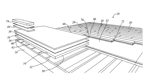
[0015] Figure 1 shows an exploded perspective general arrangement view of
framing and
flooring structure incorporating an aspect of the present invention;
[0016] Figure 2 shows a top view of a sub-floor laminate of Figure 1;
[0017] Figure 3 shows a sectional view of first and second laminates
of the flooring
structure of Figure 1;
[0018] Figure 4 shows an exploded perspective view of a general arrangement
of an
alternate, three-part laminate flooring structure to the two part flooring
structure
of Figure 1; and
[0019] Figure 5 shows a sectional view of first and second laminates
of the flooring
structure of Figure 4.
CA 02957524 2017-02-09
- 4 -
Detailed Description
[0020] The description that follows, and the embodiments described
therein, are provided by
way of illustration of an example, or examples, of particular embodiments of
the principles of the
present invention. These examples are provided for the purposes of
explanation, and not of
limitation, of those principles and of the invention. In the description, like
parts are marked
throughout the specification and the drawings with the same respective
reference numerals. The
drawings may be understood to be to scale and in proportion unless otherwise
noted. The
wording used herein is intended to include both singular and plural where such
would be
understood, and to include synonyms or analogous terminology to the
terminology used, and to
include equivalents thereof in English or in any language into which this
specification may be
translated, without being limited to specific words or phrases.
[0021] The drawings may be taken as being to scale, or generally
proportionate, unless
indicated otherwise. In the cross-sections, the relative thicknesses of the
materials may typically
not be to scale, with the thickness of cladding materials typically being
substantially exaggerated
for the purposes of explanation.
[0022] The scope of the invention herein is defined by the claims.
Though the claims are
supported by the description, they are not limited to any particular example
or embodiment, and
any claim may encompass processes or apparatus other than the specific
examples described
below. Other than as indicated in the claims themselves, the claims are not
limited to apparatus
or processes having all of the features of any one apparatus or process
described below, or to
features common to multiple or all of the apparatus described below. It is
possible that an
apparatus, feature, or process described below is not an embodiment of any
claimed invention.
[0023] The terminology used in this specification is thought to be
consistent with the
customary and ordinary meanings of those terms as they would be understood by
a person of
ordinary skill in the art in North America. The Applicant expressly excludes
all interpretations
that are inconsistent with this specification, and, in particular, expressly
excludes any
interpretation of the claims or the language used in this specification such
as may be made in the
USPTO, or in any other Patent Office, other than those interpretations for
which express support
can be demonstrated in this specification or in objective evidence of record,
demonstrating how
the terms are used and understood by persons of ordinary skill in the art, or
by way of expert
evidence of a person or persons of experience in the art.
CA 02957524 2017-02-09
- 5 -
[0024] In this discussion it may be helpful to make reference to a
Cartesian co-ordinate
system of length, width, and thickness. Many of the materials discussed herein
may be supplied
in roll form, or in the form of sheets. In general, the direction of
unrolling, or the direction of
advance of feedstock, may be considered the lengthwise or x-direction. The
breadthwise or
widthwise dimension of the roll perpendicular to the direction of advance, may
be considered the
y-direction. The through thickness of the material may be considered the
vertical or z-direction.
Many of the materials are supplied in a flexible web form in which the through-
thickness
dimension is small, or very small, as compared to either the running length in
the x-direction, or
the width in the y-direction.
[0025] The commonly used engineering terms "proud", "flush" and "shy"
may be used
herein to denote items that, respectively, protrude beyond an adjacent
element, are level with an
adjacent element, or do not extend as far as an adjacent element, the terms
corresponding
conceptually to the conditions of "greater than", "equal to" and "less than".
[0026] Referring to Figures 1 and 2, a structural assembly is
indicated generally as 20.
Structural assembly has the form of floor joists 22 carried between headers
24, in the manner of
wood frame construction such as is common in North America. While this
description is made in
the context of flooring, it also has applicability to wall coverings. Such
wall coverings may also
be mounted to wooden framed walls.
[0027] An array 28 of flooring assemblies 30 is applied to the
framing structural assembly
20. Each flooring assembly 30 includes a first pre-fabricated laminate 32 and
a second pre-
fabricated laminate 34. Typically there may be several, or many, second pre-
fabricated laminates
34 for each panel of first pre-fabricated laminate 32.
[0028] First pre-fabricated laminate 32 has a first layer 36 and a
second layer 38. First layer
36 is a matrix material 40. The matrix material is a material that has been,
or is, substantially
dimensionally stabilized. That is to say, it may be an engineered floor panel.
Matrix material 40
may typically be a wood product, or wood substrate 42. For example, it may be
a high quality
multilayered plywood. The plywood may be of greater-than usual thickness. That
is, while it
may be common to use sub-floor plywood of nominal 1/2" thickness (actual
thickness 15/32",
wooden substrate 42 may be made of thicker material such as nominal 3/4"
plywood (actual
thickness 23/32") or greater. Whereas thinner or lower grade plywoods may have
as few as 7
layers, the plywood may have greater than 8 layers, and in one embodiment may
have at least 10
CA 02957524 2017-02-09
- 6 -
layers. The layers may be without blemishes, (i.e., free of loose knots) and
the plywood may be
good-two-sides. It is desirable that the plywood have the same elasticity in
the x-direction (long
dimension of the sheet) and in the y-direction (cross-wise dimension of the
sheet). It is also
desirable that the plywood by fully dried to an equilibrium condition, which
may typically be to
a moisture content of about 10% by weight, or less.
[0029] Second layer 38 is a layer that is magnetically participating.
As used in this
specification the term "magnetically participating" means that it is either
itself magnetic, or is a
material that can become magnetic, or that can be attracted to a magnet. In
that context, the most
ubiquitous ferromagnetic material is mild sheet steel. To the extent that
sheet steel is used, it may
also be galvanized. The feedstock of this process may be galvanized steel
sheet 42, such as may
be provided in rolls. The sheet steel may be in the range of 0.0010 ¨ to about
0.040 thick. in one
embodiment it may be about 0.030 thick. The sheet may be "good one side",
i.e., the top side
may be smooth and clear, as in the rightmost portion of Figure 2.
Alternatively, as suggested in
the scab illustrations in the leftmost and center portions of Figure 2, sheet
42 may be perforated,
as with perforations 46 which may be round in the leftmost portion, or as at
48 in the center scab
portion of Figure 2, the perforations may be slots as stamped or pierced, as
shown at 50. The
characteristic width or diameter of such perforations may be less than the
through-thickness of
second laminate 34 at the edge of the sheet, and may be less than three times
that dimension in
the body of the sheet. A pierced structure may have prongs as in cleats used
in fastening
softwood lumber trusses. The perforations may be used to reduce the overall
weight of the
structure. Where a continuous, non-perforated sheet is used, the sheet may
have substantially
uniform in-plane physical properties in the x and y directions.
[0030] Second layer 38 may be bonded to first layer 36 by an adhesive, or
adhesive layer 26.
Alternatively, second layer may be a barbed or pronged layer as in WIPO
publications WO
13/177667 of Arbesman et al., and WO 13/188951, also of Arbesman et al. The
hooks may be
quite small. That is, their height from the base web, or skin, may be in the
range of 30/1000" to
70/1000", or between 150% and 300 % of the thickness of the sheeting
generally, with a density
of between 30 and 200 pointed structures per square inch, as indicated by
Arbesman et al. They
define mechanical interlocking members that embed in the softer material. This
interconnection
may tend not to require lay-up, or vacuum bags, or a curing time in an
autoclave.
[0031] On assembly, layers 36 and 38 may be mated together, whether
for adhesive bonding
and curing, or for mechanical inter-attachment. In either case, the laminate
may be assembled
CA 02957524 2017-02-09
- 7 -
under dimensionally controlled conditions. That is, in contrast to an in situ
application over
which there may be little dimensional control, the two layers may be passed
through a press, or
calendared between rollers to yield a dimensionally uniform, and dimensionally
controlled,
product. The metal top sheet may then define a flange mounted to the
underlying wooden matrix.
The matrix member need not necessarily by plywood. It could, for example, be
dimensionally
stabilized and dried oriented strand board (OSB) or OSB with a good-one-side
or good-two-sides
surface ply, or plies. It could, alternatively, be an engineered plastic,
which may include
reinforcing fillers or fibers. However, plywood may typically be convenient.
100321 Additionally, the metal surface layer may be provided with pre-
drilled mechanical
fastener apertures, or fastening accommodations, as at 52, and such as may
also be countersunk.
They may be placed on suitable spacings, as for 12", 16", 19.2", and 48"
centers. Apertures 52
may provide for multiple alternative standard spacings. It is not necessary
that all of apertures 52
by used on assembly. Such apertures may aid in positioning a sheet relative to
the underlying
joists. Further, however, they may tend to aid in making sure that mechanical
fasteners used to
mount the sheets to the underlying framing do not stand proud of the metal
layer, and to do so
without the added effort of driving a screw through a steel sheet, and without
local distortion or
plastic local deformation of the sheet such as might otherwise occur. It is
desirable that
mechanical fasteners used for installation be flush or shy of the surface
plane so that they do not
interfere with the planar engagement of second laminate 34 with first laminate
32. The side
edges 54 and end edges 56 of first laminate 32 may be finished edges. That is
to say, side edges
54 milled to be square corners and sides and to have close tolerance
dimensions to, e.g., a 96" x
48" sheet. That is, a typical size of first laminate 32 may be a 4 ft. x 8 ft.
sheet. Other sizes could
be used, e.g., 4 ft x 4 ft, or sizes based on 2ft, 30 in., 32 in. or 36 in
wide strips and suitable
lengths, 4 ft, 5 ft, 6ft, 8 ft, 12 ft., etc., as may be. The metal layer may
be of the same milled
dimensions, or it may be slightly smaller. If smaller, it may be that the
extent by which it is
smaller is less than the through-thickness dimension, t34, of second laminate
34.
[0033] Second laminate 34 may, likewise, have a first layer 62 and a
second layer 64 that
may be secured to each other with a layer of adhesive 60. Alternatively, where
second layer 64 is
a cast product, first layer 62 may have mechanical interconnection features
that are captured in
the cast product. As may be understood, the through thickness of the adhesive
layer is
exaggerated for the purposes of illustration. First layer 62 is the surface
layer, and is the "tile" or
"plank" 66. That is, it may be a ceramic, or wood, or wood simulating
composite or ceramic that
has a first surface 68 that is the display surface of the assembly that will
be visible to users of the
CA 02957524 2017-02-09
- 8 -
installed finished parts. In some embodiments first surface 68 may be a
textured surface. In other
embodiments first surface 68 may be a flat surface. First layer 62 may be a
stone or engineered
stone material. First layer 62 may be opaque, or it may be a glass or glass-
like material of full or
partial transparency or translucency. Where it is a glass material, it may be
safety (i.e.,
tempered) glass. The glass may be coloured or it may have a coloured backing.
The glass may
have beveled edges. Where glass is used, the installation may be for a wall or
backsplash, as in a
kitchen or washroom. It may in some cases carry a mirrored or patterned
backing. Where it is a
glass or glass-like like material, bonding with adhesive may be used in
respect of attachment to
second layer 64.
[0034] Each of the side facing edges 70 (lengthwise), 72 (cross-wise)
may be finished edges.
That is, edges 70, 72 may be ground or milled, as appropriate, to give an
abutment face
substantially perpendicular to the plane P68 of first surface 68. As noted,
first surface 68 may be
a textured surface that is not, in fact, planar. In this description, P68 may
be considered to be the
mean surface plane, and may be taken as being parallel to the plane of second
surface 76. The
faces of edges 70, 72 may also be planar. That is, edges 70, 72 could be
formed to a curved or
toothed shape for interlocking engagement with other pieces of mating shape.
However, most
typically those faces may be flat for planar abutting engagement of the next
adjacent member in
the array of tiles. As laminates 34 are pre-fabricated, the degree of
straightness and flatness is
subject to close tolerance control at the time of manufacture, under
conditions of precision that
would be improbable at the location of installation of the end product. In
some embodiments,
edges 70, 72 may be painted with a very thin coating of plastic resin or
sealer. In an alternate
embodiment, the edge of the tile may have a two sided tape or polymer of very
small thickness ¨
e.g., single or double sided Kapton (t.m.) Polyimide tape, double sided, or
merely the 0.0004"
thick adhesive layer applied directly to the ceramic.
[0035] Second layer 64 is a magnetically participating layer. Again,
the manner in which it
is mounted to the backside, or underside 76 of the tile member is controlled
at the point of
manufacture. The tile is generally of high uniformity of thickness, and
underside 74 is typically
of high uniformity of flatness. The application of adhesive, the mounting of
second layer 64, and
the curing of the assembly as all subject to process control in a factory
setting. Thus the flatness
of second layer 64 may correspond to the flatness of later 38. It may be
convenient for layer 64
to be co-extensive with layer 62. This need not be so. Layer 64 may be smaller
in each or both
of the x and y directions, while remaining substantially co-extensive with the
ceramic layer in
terms of overall footprint, whether layer 64 is perforated or slotted, or a
solid uniform monolith.
CA 02957524 2017-02-09
- 9 -
The extent to which it is smaller at each edge may be less than the thickness
of second laminate
34. Layer 64 may tend to be much thinner in through-thickness t64 than is
layer 62, as shown at
t62. That is t62 may tend to be of the order of 1/4" (6 mm) to 1/2" (13 mm)
thick, and may in one
embodiment be about 5/16" thick (8 mm) or 3/8" (10 mm) thick. By contrast,
layer 64 may be
less than 1/16" thick, as at t64. It may be about 1.5 mm thick. Layer 64 may
be made of sheet
metal, such as mild steel sheet or any other ferromagnetic material, as
described above in the
context of layer 38. Typically, one or the other of layer 64 and layer 38 is
magnetic, such that the
two layers are mutually attracted. Given that first laminate 32 may tend to be
laid before second
laminate 34, and may tend to be exposed, at least temporarily to dust and
other impurities, it may
be convenient for layer 64 to be the magnetic layer. In such case, layer 64
may be made of a
polymer impregnated with magnetic particles, such as are commercially
available. One example
of such a product is [identify].
[0036] On installation, first laminate 32 is mounted to the
underlying framing structure, or to
such other structure as may be. Second laminate 34 is then mounted to first
laminate 32 by
placement and magnetic attraction. To the extent that second laminate 34 is to
be repositioned, it
may be lifted with suction cups. Given that edges 70, 72 are finished edges,
they may tend to fit
together with the corresponding edges 70, 72 of the next adjacent tiles in
flush, planar abutment.
The close fit of milled edges is not intended to require grouting.
[0037] To the extent that neither mortar nor grouting may be
required, the cost of installation
of tiles such as assemblies 30 may tend to be relatively low. It may also be
relatively quick, and
may not require the curing of chemicals. Furthermore, the use of a magnetic
assembly may tend
to permit the replacement of parts at a later date that does not tend to
require destruction of either
the tiling or the surface.
[0038] The use of magnetic flooring systems is known. Most typically
they pertain to
flexible plastic, or vinyl, or linoleum, tiles or sheets that are placed on a
substrate. One such
assembly is shown in US patent 3,341,996 of Jones, or 5,752,357 of Piller,
and, latterly, of
8,656,682 of Williamson. An elastomeric sheet of this nature may have a
thickness of less than
1/8", sometimes quite substantially less; and may have a Young's modulus of
perhaps 450,000
psi (3 GPa). By contrast a ceramic or ceramic-based tile may have a thickness
of 5/16" and a
Young's modulus of 10 to 20 x 106 psi (70 ¨ 140 GPa). Although the tiles have
a modest flex
(e.g., 1" over a 72" length), the flexural modulus of the ceramic tile may
typically be 200 ¨ 500
times greater than rollable or peelable tile. It may also tend to have a much
lower co-efficient of
CA 02957524 2017-02-09
- 10 -
expansion in the presence of changes in humidity. The thicker, ceramic based
tile does not bend
or stretch in the manner of a polymer-based tile or roll-supplied sheet
flooring. In this
specification and the claims herein, the thicker flooring members described
herein may be
referred to as stiff or rigid members, or non-bending members, in distinction
to peelable or
rollable flexible polymeric floor coverings. The use of a metal layer on the
sub-floor matrix may
tend also to cause the subfloor to have an elasticity and flexural modulus
that is relatively
compatible with the tile. That is, although the galvanized steel sheet may be
relatively thin, it has
a Young's modulus of 30 x 106 psi (210 GPa) and is backed by a thicker matrix.
The in-plane
stretching of the floor may tend to be dominated by the properties of the
galvanized steel sheet,
those properties being of a comparable order of magnitude to the properties of
the tiles.
[0039] Accordingly, given the rather different physical properties,
the placement and
installation of the thicker, stiffer tiles is a different matter than the
placement of soft peelable or
rollable tiles or sheets. When the stiff, typically ceramic-based, tiles
described herein are laid,
their edges mate on a tight seam or interface. That seam may tend to be
dimensionally stable.
Where tiling is used, either in the context of flooring or of wall members,
and the tiling is a
ceramic such as a glass or porcelain, a mis-match of dimensions may be visible
as a distortion in
reflection. This may tend to be reduced by the use of tightly fitting edges
and dimensionally
controlled components. As compared to conventional ceramic tiling, the use of
the magnetic
tiling herein may allow the elimination of mis-match in lie caused by the
variation of thickness
of a mortar, and the need for grouting. Where flat ground edges are mated in
abutting contact,
the line of contact may tend not to admit entry of a piece of paper. The
resultant assembly may
appear seamless.
[0040] Second laminate 34 may be of many different sizes or aspect ratios.
That is, while
square tiles may be used, it may be that generally rectangular tiles
simulating wood planks may
also be used. It is not necessary that all tiles be the same length or the
same width. It is, however,
expected that even where a variety of tile sizes is used, the cross-wise and
length-wise
dimensions may nominally yield integer divisions of the sheets panels of first
laminate 32.
Where the space to be tiled, be it a floor or wall, is not equal to an integer
number of first
laminates 32 or second laminate 34, or both, as may be, either or both may be
cut to size.
[0041] In a further embodiment as shown in Figure 4, there is a
flooring assembly 80 that is
substantially similar to flooring assemblies 30. First laminate 82 may be
taken as being the same
as first laminate 32. Second laminate 84 may be the same as second laminate
34. Assembly 80
CA 02957524 2017-02-09
- 11 -
differs from assembly 30 to the extent that neither first laminate 32 nor
second laminate 34 need
include magnets. They may be passive, e.g., both may have ferromagnetic sheets
that are not
initially magnetized. Rather, a magnetic sheet 86 is a two-sided magnetic
sheet placed between
first laminate 82 and second laminate 84, and is attractive to both of them,
such that there is a
three part, or three layer, assembly or sandwich.
[0042] In such an assembly, the magnetic sheet need not be
continuous. That is, is could
have discrete openings or gaps, or be formed in an array of strips, whether
interspersed with non-
metallic material or otherwise. The metal backing of the ceramic tile would
then function as a
tensile reinforcement plane on the back-side of the ceramic sheet.
[0043] The tiles are made of a ceramic material, which may be
porcelain, with a magnetic
layer bonded to the underside of the tile. The magnetic material may be a
sheet having many
dipole magnets per square foot. The sheet itself may tend to be substantially
rubbery, in the
manner of a rubber mat. The hold-down force of the sheet may be in the range
of 100 lb/sq.ft.
The tile may be of a particularly elastic ceramic material such as provided by
[Identify Source
of Material] The tile may be textured tile, and may be supplied in a plank or
plank-like form.
[0044] Although the various embodiments have been illustrated and
described herein, the
principles of the present invention are not limited to these specific examples
which are given by
way of illustration, but only by a purposive reading of the claims.