Note: Descriptions are shown in the official language in which they were submitted.
CA 02957685 2017-02-08
WO 2016/025205 PCT/US2015/043384
1
HANDHELD FLUOROMETER
FIELD
[01] This disclosure generally relates to systems and methods for measuring
concentration of
chemicals in a solution. More particularly, this disclosure relates to systems
and methods
involving a fluorometer for measuring concentration of chemicals in a
solution.
BACKGROUND
[02] Cleaning operations in public facilities such as restaurants, hotels,
food and beverage
plants, hospital, etc. typically uses a cleaning product having sanitizing,
disinfecting
and/or antimicrobial properties. In some cases, cleaning products may interact
with
certain chemical compounds (e.g., dipicolinic acid) present in some microbial
spores to
destroy microbes. Alternatively, certain chemical compound may be added to
cleaning
products to improve their chemical stability and/or shelf-life. For instance,
dipicolinic
acid can be added to certain cleaning products to improve their resistance to
heat, thereby
reducing the rate of degradation of the cleaning products when exposed to heat
and
extending the use of such cleaning products in regions with warm climates.
[03] The concentration of dipicolinic acid may be measured in a number of
situations. For
instance, regulatory standards may require that the concentration of microbial
spores not
exceed a given value in a public facility. By measuring the concentration of
dipicolinic
acid, the concentration of microbial spores may then be determined to comply
with any
regulatory standard. In another example, it may be necessary to maintain a
certain
concentration of dipicolinic acid to improve the stability of cleaning
products. As
dipicolinic acid exhibits fluorescence when excited by electromagnetic
radiation of
certain wavelengths, the concentration of dipicolinic acid in a solution can
be measured
by measuring the fluorescence of the solution. The intensity of fluorescence
emitted by
the solution may depend on the concentration of dipicolinic acid in the
solution. For
instance, the intensity of fluorescence emitted by the solution may be
directly proportion
to the concentration of dipicolinic acid. By measuring the intensity of the
fluorescence
emitted by dipicolinic acid, the concentration of dipicolinic acid can
therefore be
determined.
2
[04] Fluorometers for measuring fluorescence of a sample are relatively
well known. An
exemplary fluorometer for measuring fluorescence is disclosed in U.S. Pat. No.
8,269.193 and U.S. Pat. No. 8,352,207 both assigned to Ecolab Inc.. St. Paul,
MN.
Fluorometers generally have of a source of electromagnetic radiation that can
excite a
sample (e.g.. dipicolinic acid solution of an unknown concentration), and a
detector
adapted to measure the intensity of fluorescence emitted by the
electromagnetic radiation.
[05] In many situations the concentration of a substance of interest (e.g.,
dipicolinic acid) in a
solution (e.g., cleaning solution) may be very low. For instance, regulatory
requirements
may necessitate that only a minimum level of the substance of interest (e.g.,
microbes) is
present in a target area (e.g., a healthcare facility, food and beverage
production and
packaging facility). In such cases, the intensity of fluorescence emitted by
such
substances of interest can be proportional to their concentration. Low
concentrations
(e.g., on the order of a few hundred parts per billion) may result in decrease
in intensity
of emitted fluorescence. For instance, the fluorescence may decrease directly
proportional to the decrease in concentration (or by diluting the substance of
interest).
Typical fluorometers known in the art may not be able to measure such low
levels of
fluorescence with high accuracy and sensitivity.
SUMMARY OF THE INVENTION
[06] Certain embodiments of the invention include a fluorometer for measuring
fluorescence
of a sample. The fluorometer can include a housing, a controller supported by
the
housing, and a sensor head. The sensor head can include an emitter module and
a detector
module operatively coupled to the controller. The emitter module can include
an
excitation source configured for emitting electromagnetic radiation at one or
more
wavelengths to induce fluorescence in the sample. The emission of the
electromagnetic
radiation can be directed along a first beam path. The sensor head can include
an
excitation filter for transmitting electromagnetic radiation within a first
wavelength range
toward the sample. The excitation filter can be supported by an excitation
filter holder.
The excitation filter holder can define an aperture for passage of
electromagnetic
radiation. The excitation filter holder can support the excitation filter such
that the
CA 2957685 2020-03-17
CA 02957685 2017-02-08
WO 2016/025205 PCMJS2015/043384
3
excitation filter permits passage of filtered electromagnetic radiation
through the aperture
and towards the sample such that the first beam path defines a trajectory of
electromagnetic radiation from the excitation source to the excitation filter,
via the
aperture and toward the sample. The detector module can detect fluorescence
emitted by
the sample. The fluorometer displays the concentration of the substance in the
sample
determined by the controller, based on the measured fluorescence.
[07] In some embodiments, the fluorometer includes a first focusing apparatus
and a second
focusing apparatus. The first focusing apparatus and the second focusing
apparatus can
be housed in the housing proximate the sensor head. The first focusing
apparatus can
direct electromagnetic radiation originating from the excitation source and
transmitted by
the excitation filter towards the sample. The second focusing apparatus can
direct
fluorescence originating from the sample toward the detector module.
[08] In some embodiments, the aperture can be positioned asymmetrically
relative to the first
beam path such that the aperture passes an asymmetrical portion of the
electromagnetic
radiation in the first beam path and the excitation filter holder blocks
passage of a
corresponding asymmetrical portion of the electromagnetic radiation in the
first beam
path. The blocked passage of the corresponding asymmetrical portion of the
electromagnetic radiation in the first beam path can reduce the amount of
electromagnetic
radiation oriented directly from the emitter module to the detector module. In
some
embodiments, the aperture is of semi-circular cross-section. In some
embodiments, the
aperture is shaped by obstructing at least a portion of a circular opening. In
some
embodiments, the aperture is shaped to prevent electromagnetic radiation
passing through
the first focusing apparatus from being directed toward the second focusing
apparatus.
[09] The details of one or more embodiments of the invention are set forth in
the
accompanying drawings and the description below. Other features, objects, and
advantages will be apparent from the description and drawings, and from the
claims.
BRIEF DESCRIPTION OF THE DRAWINGS
[10] The following drawings are illustrative of particular embodiments of the
present
invention and therefore do not limit the scope of the invention. The drawings
are not
necessarily to scale (unless so stated) and are intended for use in
conjunction with the
CA 02957685 2017-02-08
WO 2016/025205 PCMJS2015/043384
4
explanations in the following detailed description. Embodiments of the
invention will
hereinafter be described in conjunction with the appended drawings, wherein
like
numerals denote like elements.
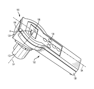
[11] FIG. 1 is a perspective view of a fluorometer according to an embodiment
of the
invention;
[12] FIG. 2 is an exploded perspective view of the fluorometer of FIG. 1;
[13] FIG. 3 is a perspective view of a sensor head of a fluorometer according
to an
embodiment of the invention;
[14] FIG. 4 is a cross-sectional front view of the sensor head of FIG. 3 taken
along the
sectional plane A-A;
[15] FIG. 5 is an exploded perspective view of the sensor head of FIG. 3;
[16] FIG. 6 is a perspective view of an emitter module of a fluorometer
according to an
embodiment of the invention;
[17] FIG. 7 is an exploded perspective view of the emitter module of FIG. 6;
[18] FIG. 8 is a perspective view of a detector module of a fluorometer
according to an
embodiment of the invention;
[19] FIG. 9 is a graph showing excitation and fluorescence emission spectrum
of the
fluorometer according to an embodiment of the invention;
[20] FIG. 10A is a graph showing the transmittance spectra of the excitation
and emission
filters along with the excitation and fluorescence emission spectra according
to an
embodiment of the invention;
[21] FIG. 10B is a graph showing the transmittance spectra of the excitation
and emission
filters along with the excitation and fluorescence emission spectra according
to another
embodiment of the invention;
CA 02957685 2017-02-08
WO 2016/025205 PCT/1JS2015/043384
[22] FIG. 11 is a perspective view of a portion of the emitter module of FIG.
3 according to an
embodiment of the invention;
[23] FIG. 12A-12D are front views of a portion of the emitter module according
to various
embodiments of the invention; and
[24] FIG. 13 is a side view of an emitter module according to another
embodiment of the
invention.
DETAILED DESCRIPTION
[25] The following detailed description is exemplary in nature and is not
intended to limit the
scope, applicability, or configuration of the invention in any way. Rather,
the following
description provides some practical illustrations for implementing exemplary
embodiments of the present invention. Examples of constructions, materials,
dimensions,
and manufacturing processes are provided for selected elements, and all other
elements
employ that which is known to those of ordinary skill in the field of the
invention. Those
skilled in the art will recognize that many of the noted examples have a
variety of
suitable alternatives.
[26] FIGS. 1 and 2 are perspective and exploded views, respectively, of a
fluorometer 100
according to some embodiments of the invention. The fluorometer 100 can be
useful for
measuring fluorescence emitted by certain samples. Moreover, the fluorometer
100 can
facilitate determining the concentration of certain samples in a solution
based on the
measured fluorescence. Such embodiments can be useful for measuring intensity
of
fluorescence emitted by samples such as dipicolinic acid and other chemicals
(e.g., found
in cleaning products). Based on the measured intensity of emitted
fluorescence, the
concentration of dipicolinic acid in a solution (e.g., a sanitizer,
disinfectant, detergent,
and the like) can be determined.
[27] In general, the fluorometer 100 can measure intensity of fluorescent
emission from a
sample (e.g., a chemical solution, such as an antimicrobial or cleaning
product) having a
substance of interest (e.g., dipicolinic acid). The fluorometer 100 can
calculate
concentration of the substance in the sample, and display the determined
concentration to
CA 02957685 2017-02-08
WO 2016/025205 PCMJS2015/043384
6
a user. The user can then perform any desired actions based on the determined
concentration, such as, for example, adding more of the substance in order to
increase the
concentration of the substance. If the fluorometer 100 determines that the
concentration is
lower or higher than a threshold concentration, the user can dispense more or
less of the
substance. Additionally, the fluorometer 100 can be operatively coupled to an
out-of-
product sensor. In certain embodiments, when the concentration of the
substance is below
a pre-determined threshold, the fluorescence emitted by the substance may be
at a lower
intensity. At this point, the out-of-product sensor can alert the user that
the concentration
of the substance has reached below a pre-determined threshold. The signal can
be a
visual, audio signal, or any other type of signal known in the art.
Accordingly, the user
can ensure that sufficient quantity and/or concentration of cleaning,
antimicrobial,
sanitizing and/or disinfecting solution, or other substances of interest is
present to achieve
the desired effect (cleanliness, reduction in microorganisms, heat resistance,
product
stability, lubrication, etc.).
[28] The basic operation of a fluorometer 100 is well known, and accordingly,
various details
are omitted here for conciseness and clarity. The fluorometer 100 can
calculate a
concentration of a particular substance in a sample based on fluorescent
properties of the
substance. As will be described in more detail herein, the fluorometer 100
includes an
excitation source 158 that emits electromagnetic radiation at one or more
selected
wavelengths, or continuously within a wavelength range. When the substance of
interest
is exposed to electromagnetic radiation at one or more selected wavelengths,
(e.g., within
a wavelength range), it may cause excitation of electrons in certain molecules
of the
substance and induce them to emit electromagnetic radiation. The emitted
electromagnetic radiation can be of a different energy (i.e., at another
wavelength range)
from the electromagnetic radiation emitted by the excitation source 158. The
electromagnetic radiation emitted by the substance can then be converted into
an
electrical signal. The electrical signal can indicate the intensity of
fluorescent emissions.
The concentration of the substance can then be determined based on a known
relationship
between the intensity of the fluorescent emissions and the concentration of
the substance
(e.g., via a calibration).
7
[29] A number of variations and specific details of this general process are
contemplated for
embodiments of the invention involving fluorometers. In one example the
concentration
of water treatment products or solutions may be determined. In another
example. the
substance of interest may be any chemical solution. Examples include, but are
not limited
to. biocides such as pesticide and antimicrobial products, anticorrosion,
antiscaling, and
antifouling products, disinfectants, and other cleaning products, detergents,
additives.
surfactants, lubricants, antimicrobial agents, solvents, hydrotropes,
antiredeposition
agents, dyes. corrosion inhibitors, acids, alkaline solutions, salt solutions,
and bleaching
additives. These compounds can be incorporated into products like ware-washing
detergents, rinse aids, laundry detergents, clean-in-place cleaners.
antimicrobials. tloor
coatings, meat, poultry and seafood carcass treatments, pesticides, vehicle
care
compositions, water care compositions, pool and spa compositions, aseptic
packaging
compositions, bottle washing compositions. and the like. Examples of some of
these
compounds and corresponding applications can be found in U.S. Pat. No.
7,550.746
assigned to the assignee of the instant application.
POI As seen in FIGs. 1 and 2, the fluorometer 100 includes a sensor head
102. The sensor
head 102 can be made from a plastic and may be molded and/or milled to achieve
the
desired shape and features. The sensor head 102 includes a fluid-tight sensor
head
housing 104 (e.g., 0-ring seals) that facilitates operation of the fluorometer
100 when
partially or wholly immersed in a fluid sample of interest, and protects
various
components of the sensor head 102 from exposure to fluids. Accordingly, in
some cases
the sensor head 102 has some features and/or characteristics similar to an
immersible dip
probe. For example. in some embodiments of the invention the sensor head 102
has one
or more features and/or components similar to those described in commonly-
assigned
U.S. Pat. No. 7,550,746, U.S. Pat. No.7,652,267, U.S. Pat. No.7,989,780, and
U.S. Pat.
No. 8,084,756 all assigned to the assignee of the instant application.
The sensor head 102 can be
immersed into a sample container (not shown) to measure fluorescence and/or
concentration. The fluorometer 100 also includes an electronic display 106 for
displaying
data (e.g., concentration, intensity), to a user, and an input interface in
the form of the
CA 2957685 2020-03-17
CA 02957685 2017-02-08
WO 2016/025205 PCMJS2015/043384
8
keypad 108 that allows the user to interact with the fluorometer 100 (e.g.,
saving
measured concentration or intensity, setting parameters for measurement,
viewing
previously stored measurement data, etc.).
[31] The sensor head 102 can be connected to a controller module 110. In some
embodiments,
the controller module 110 has a controller housing 112 which provides a
convenient
form, similar to a handle or wand, to easily grasp or hold the fluorometer 100
by hand. In
some embodiments, the controller module 110 generally includes those
components
necessary to determine a concentration of a product based on a signal received
from the
sensor head 102. As shown in FIG. 2, the controller module 110 includes a
controller
board 114 that couples with a display board 116 via a display board cable. The
display
board 116 allows the electronic display 106 (e.g., an LCD screen) to display
information
(e.g., measured concentration, intensity of fluorescence) to a user. The
controller module
110 also includes an input interface in the form of a keypad 108. The
controller module
110 also includes a portable power source 120, (e.g., battery) for powering
the
fluorometer 100.
[32] In some cases, the sensor head 102 is connected to (e.g., by fasteners or
adhesives) or
integral with a bottom surface 122 of the controller housing 112 opposite from
the
electronic display 106 and positioned proximate a distal end 124 of the
controller housing
112. In some embodiments, the sensor head 102 housing is fixedly attached to
the bottom
surface 122 of the controller housing 112. In some embodiments, the sensor
head housing
104 may be integrally formed with at least a portion of the controller housing
112. In one
example, a user can grasp the controller housing 112 near a proximal end 126
of the
controller housing 112 to take measurements from a sample. Additionally, the
user can
grasp the controller housing 112 near the proximal end 126 of the controller
housing 112
to read the electronic display 106, and/or to manipulate the keypad 108. For
example, a
user may dip the sensor head 102 into a sample by holding the controller
module 110
above the surface of a sample (e.g., in a reservoir, container, beaker, etc.)
with the sensor
head 102 partially or completely immersed in the sample. In some embodiments,
a user
may grasp the proximal end 126 of the controller module 110 while securing a
sample
9
container to the sensor head 102. Other configurations of the controller
module 110 and
the sensor head 102 are also possible.
[33] Referring back to FIG. 2, the controller board 114 can have a number of
discrete
components positioned (e.g.. soldered) and coupled together on a printed
circuit board.
The controller board 114 includes a controller 128, which calculates a
concentration
based on an intensity signal from the detector module 150. The controller 128
may
provide a variety of other functions, including but not limited to, performing
a calibration
routine, accepting and executing instructions entered at the input interface,
and/or
formatting data for viewing on the fluorometer's electronic display 106. The
controller
128 can be any of the controllers known in the art, such as a software driven
microprocessor, a microcontroller, a field programmable gate array, an
integrated circuit,
and the like. In addition, the controller 128 or the controller board 114 may
have on-
board memory (not shown) that stores instructions for execution by the
controller 128.
[341 The controller board 114 also includes a power cable 130 for connecting
the controller
board 114 (e.g., via a connector) to the power source 120 shown in FIG. 2. The
controller
board 114 also includes one or more power supplies (not shown) for powering
the
excitation source 158 in the sensor head 102. In some embodiments the
controller board
114 includes a real-time clock battery. a lock-in amplifier, a reference
photodetector
amplifier, and connectors for the display board 116, the emitter module 140.
and the
detector module 150. In some cases, the controller board 114 may also have a
USB or
other type of connector. connection devices (e.g.. Ethernet card. wireless
adapter,
cellular adapter and the like) for communicating with other computing devices.
[35] In some embodiments the sensor head 102 has one or more features and/or
components
similar to those described in commonly-assigned U.S. Pat. No. 7,550,746 and
U.S. Pat.
No. 8.084,756.
Referring now to FIGS. 3 and 4, in some embodiments, the sensor head
housing 104 houses an emitter module 140 (best seen in FIGS. 6 and 7) and a
detector
module 150 (best seen in FIG. 8). The components on the emitter module 140 and
the
detector module 150 can be held in chambers -Cl" and "C2" that encloses each
board, as
seen in FIG. 5. The first chamber -C I" receives the emitter module 140. The
first
CA 2957685 2020-03-17
CA 02957685 2017-02-08
WO 2016/025205 PCMJS2015/043384
chamber "Cl" can be of cylindrical shape. The second chamber "C2" receives the
detector module 150. In some cases, the first chamber Cl and the second
chamber C2 may be positioned symmetrically about the longitudinal axis "SA" of
the
sensor head 102 (e.g., with a vertical orientation). Each chamber "Cl" and
"C2" includes
a cutout, and the sensor head housing 104 extending through the housing. These
cutouts
156 allow electromagnetic radiation from an excitation source 158 (e.g., from
an LED
source) positioned on the emitter module 140 and an emission detector 194
(e.g.,
phototransistor) positioned on the detector module 150 to communicate with an
analytical
area outside the sensor head housing 104. Electrical cables couple the emitter
module
140 and the detector module 150 to the controller board 114, which allows the
controller
on the controller board 114 (shown in FIG. 2) to control the excitation source
158 and
receive signals back from the emission detector 194. While not illustrated, in
some
embodiments the sensor head 102 also includes one or more temperature sensors
that are
able to measure the temperature of a water sample. For example, the emitter
module
140 and/or the detector module 150 may include one or more temperature sensors
that
extend into the sensor head housing 104.
[36] With continued reference to FIG. 5, the excitation window 160 provides a
path through a
first wall "W 1" for the electromagnetic radiation emitted by the excitation
source 158. A
second wall "W2" similarly defines an emission detector window 162 that
provides a
path through the second wall "W2" for electromagnetic radiation emitted by the
sample
to reach the emission detector 194. In some embodiments, the excitation window
160 and/or the emission detector window 162 define a channel 164 extending
through the
sensor head housing 104. A focusing apparatus 166 may be positioned adjacent
each
window to prevent electromagnetic radiation from the excitation source 158
(e.g.,
directed toward the sample), or that emitted by the sample (e.g., toward the
emission
detector 194) from entering the channel 164. The focusing apparatus 166 can be
a lens,
mirror, prism or other optical elements known in the art for redirecting
electromagnetic
radiation. In some embodiments, the focusing apparatus 166 (e.g., ball lenses)
is made of
glass. For instance, in the illustrated embodiment shown in FIGS. 3-5, a pair
of ball
lenses 168, 170 is positioned adjacent the excitation and emission detector
194 window.
In the illustrated embodiment, the focusing apparatus 166 (e.g., ball lenses)
is made of
CA 02957685 2017-02-08
WO 2016/025205 PCMJS2015/043384
11
sapphire. In some embodiments, the focusing apparatus 166 can be (e.g., made
of
suitable materials) to be substantially transparent to the excitation and/or
emission
wavelengths. For instance, the first ball lens 168 168 can be substantially
transparent to
electromagnetic radiation emitted by the excitation source 158 and the second
ball lens
170 can be substantially transparent to electromagnetic radiation emitted by
the sample.
In some embodiments, both the first and second ball lenses 168, 170 can be
substantially
transparent to electromagnetic radiation emitted by both the excitation source
158 and the
sample. As mentioned previously, the focusing apparatus 166 can direct
electromagnetic
radiation from the excitation source 158 toward the sample and that from the
sample
toward the detector module 150. At the same time, the focusing apparatus 166
can
prevent any electromagnetic radiation (e.g., from the excitation source 158
and the
sample) from entering the channel 164 defined by the excitation window 160 and
the
emission detector 194 window. In some embodiments the excitation and emission
detector windows 160, 162 also include a lens, prism or other material
optically
transparent to the emissions.
[37] Referring back to FIG. 1, in some embodiments, the sensor head 102
includes a proximal
end 172 and a distal end 174, between which extends the longitudinal axis "SA"
and a
length "L" of the sensor head 102. As shown in FIGS. 1 and 3, in some
embodiments the
sensor head 102 is connected to the bottom surface 122 of the controller
housing 112 at
or near the proximal end 172 of the sensor head 102. The sensor head 102 may
be
positioned and oriented such that the longitudinal axis "SA" of the sensor
head 102 forms
an angle "A" with a longitudinal axis "CA" of the controller module 110. In
some cases
the sensor head 102 may be removably or fixedly attached to the controller
housing 112
with a fastener (not shown). The fastener can include, but is not limited to,
screws, bolts,
and/or pins. Alternatively, the sensor head 102 may be fixedly bonded to the
controller
housing 112 by an adhesive or by welding. In some embodiments the sensor head
102 is
secured with four screws that compress an 0-ring positioned in a groove
between the
sensor head 102 and the controller module 110. In some embodiments, the sensor
head
housing 104 may be integrally formed (e.g., molded) with the controller module
110.
CA 02957685 2017-02-08
WO 2016/025205 PCMJS2015/043384
12
[38] While not illustrated, the sensor head 102 can also include part or all
of a fastener that
removably fastens a sample container to the sensor head 102. In one example,
the
fastener may comprise one or more pins positioned about the sensor head
housing 104.
Corresponding slots on the sample container receive the pins extending form
the sensor
head 102 housing. In some embodiments the pins and the slots form a bayonet
fastener
that secures the sample container about the sensor head 102 and also aligns
the sample
container in a preferred orientation (e.g., rotation, three-dimensional
position) about the
sensor head 102. Other fasteners (e.g., screw threads, opposing pressure
elements, etc.)
can also be included. Alternatively, the sample container may engage with the
sensor
head 102 by a friction fit.
[39] While not illustrated, in some embodiments, the sensor head 102 also
includes holes for
inserting one or more temperature sensor covers. The temperature sensors (not
shown)
can sense the temperature of the water sample that can be used to correct
concentration
determination based on errors due to temperature effects. The sensor head 102
can be an
immersible sensor head. In some cases, the sensor head 102 can be partly or
wholly
immersed in a sample. Accordingly, the sensor head housing 104, controller
housing 112,
and other components can be sealed (e.g., fluid resistant seals, 0-rings and
the like) prior
to immersion. In addition, the excitation window 160 and emission detector
window
162 may also be sealed with 0-rings and the like. In some embodiments, the
excitation
window 160 and emission detector window 162 are sealed due to a pressure fit
between
the windows, channel 164, and the first and second ball lenses 168, 170 placed
within the
channel 164.
[40] As discussed above, in some embodiments, fluorescence measurements can be
taken by a
fluorometer 100 by manually lowering the sensor head 102 into a water sample.
For
example, a user can grasp the controller module 110 and temporarily dip the
sensor head
102 into a liquid sample such that the sensor head 102 is partially or
completely
immersed in the sample and the sample occupies an analytical area near the
sensor head
102 windows. In some embodiments of the invention, the orientation of the
attachment
between the sensor head 102 and the controller module 110 can be set to
provide the
fluorometer 100 with a desired inclined position on the support surface. For
example, as
CA 02957685 2017-02-08
WO 2016/025205 PCMJS2015/043384
13
mentioned previously, the sensor head 102 is connected to the controller
module
110 such that the longitudinal axis "SA" of the sensor head 102 forms an angle
"A" in the
range between about 60 degrees and about 90 degrees with the longitudinal axis
"CA" of
the controller module 110.
[41] FIGS. 6 and 7 show various views of an emitter module 140 according to
some
embodiments of the invention. As best seen in FIG. 7, the emitter module 140
(also
shown in FIG. 2 as 320) can include a printed circuit board having an
excitation source
158 and a reference photodetector 182 (best seen in FIG.13). Optionally, the
emitter
module 140 can include an amplifier 184 and a connector for coupling the
emitter
module 140 with the controller board 114. The excitation source 158 can
include a
variety of possible elements. For example, excitation source 158 may be a gas
discharge
lamp, a mercury lamp, a deuterium lamp, a metal vapor lamp, a light emitting
diode
(LED) or a plurality of LED lamps. In addition, the excitation source 158 may
emit
electromagnetic radiation in a number of possible spectrums depending upon the
excitation element chosen and the spectrum desired. In some embodiments the
excitation
source 158 is an LED lamp, capable of emitting ultraviolet (UV) radiation
having a
wavelength from about 250 nanometers to about 310 nanometers. An excitation
filter 188
is positioned in an excitation filter holder 190 to intercept electromagnetic
radiation from
the excitation source 158. The excitation filter 188 can filter the
electromagnetic radiation
from the excitation source 158 before it leaves the sensor head 102. The
excitation filter
holder 190 can define an aperture 192 for passage of electromagnetic radiation
from the
excitation source 158, via the excitation filter 188 and toward the sample.
The shape of
aperture 192 may be defined by forming it integrally within the excitation
filter holder
190 or it may be defined by forming it via an assembly of components including
the
excitation filter holder 190.
[42] The excitation filter 188 can substantially transmit electromagnetic
radiation from the
excitation source 158. In some embodiments, the excitation filter 188
configured for
transmitting electromagnetic radiation within a desired wavelength range
toward the
sample. Referring now to FIGS. 9 and 10, the excitation source 158 can emit
electromagnetic radiation at a desired wavelength or in a wavelength range. In
the
CA 02957685 2017-02-08
WO 2016/025205 PCMJS2015/043384
14
embodiment illustrated in FIG. 6, the excitation source 158 emits
electromagnetic
radiation in the spectral range between about 250 nanometers and about 300
nanometers.
For instance, if fluorescence of dipicolinic acid is to be measured, the
excitation source
158 can emit electromagnetic radiation in the spectral range between about 260
nanometers and about 285 nanometers. Optionally, an operator may enter (e.g.,
via the
keypad 108) one or more wavelengths at which electromagnetic radiation is to
be emitted
by the excitation source 158. The controller 128 may then communicate with the
emitter
module 140 so that the excitation source 158 emits electromagnetic radiation
at the
wavelengths selected by the operator. The excitation filter 188 can
substantially transmit
at least a portion of the electromagnetic radiation in at least a portion of
the excitation
spectrum (e.g., excitation peak "e" shown in FIG. 9). For instance, the
excitation filter
188 can have a transmittance "t1" of between about 50% and about 100% in the
spectral
range corresponding to excitation. In the illustrated embodiments shown in
FIGS. 9 and
10, the excitation filter 188 has a transmittance "t1" of about 75% in the
spectral range of
between about 250 nanometers and about 285 nanometers. However, other filters
having
transmittance in a spectrum encompassing the excitation spectrum can also be
used. In
one example, the excitation filter 188 can have a transmittance "tl" of
between about
50% and 100% in the spectral range of between about 150 nanometers and 380
nanometers, for excitation in the spectral range of between about 250
nanometers and
about 300 nanometers. The filtered electromagnetic radiation can then be
directed (e.g.,
by the focusing apparatus 166 shown in FIGS. 4 and 5) toward the sample to
induce
fluorescent emissions from the sample.
[43] FIG. 8 is a perspective view of a detector module 150 according to some
embodiments of
the invention. The detector module 150 can be used for detecting (e.g.,
measuring the
intensity of) the fluorescence emitted by the sample. The detector module 150
generally
includes a number of components, including an emission detector 194 positioned
on a
printed circuit board. Optionally, the detector module 150 also includes an
amplifier 184
and a temperature sensor. The emission detector 194 can be a photodiode.
Alternatively
the emission detector 194 can be a phototransistor. In some embodiments, the
emission
detector 194 can sense electromagnetic radiation emitted by the sample at a
plurality of
wavelengths. In one example, the emission detector 194 can sense
electromagnetic
CA 02957685 2017-02-08
WO 2016/025205 PCMJS2015/043384
radiation at wavelengths between about 400 nanometers and about 1500
nanometers. In
the illustrated embodiment shown in FIGS 9 and 10, the sample emits
fluorescence in the
spectral range between about 400 nanometers and about 700 nanometers. The
sample
may emit discretely (e.g., discrete intensity peaks, "f1", "f2", "f3", and
"f4" shown in
FIG. 9) at selected wavelengths (e.g., about 490 nanometers, about 550
nanometers,
about 580 nanometers, and about 620 nanometers). The emission detector 194 can
be
sensitive to fluorescence emitted by the sample at such discrete wavelengths,
and have
sufficient linearity (e.g., measured signal linearly proportional to intensity
of
fluorescence.)
[44] An emission filter holder 196 positioned about the emission detector 194
supports one or
more emission filters 198 for filtering undesirable electromagnetic radiation
and
transmitting the desired electromagnetic radiation to the emission detector
194. In the
embodiment shown in FIG. 8, the emission filter 198 is a polycarbonate filter
a thickness
between about 1 millimeter and about 10 millimeters. In some embodiments, the
thickness of the emission filter 198 can be between about 2 millimeters and
about 4
millimeters. The emission filter 198 can be of any shape (square, rectangular,
elliptical)
and in the illustrated embodiment is of circular shape. Alternatively other
filters (e.g.,
interference glass) filters can be used. Any suitable emission filters
transmitting
electromagnetic radiation emitted by the sample toward the emission detector
194, and
not transmitting (e.g., reflecting or absorbing) electromagnetic radiation at
wavelengths
other than those emitted by the sample can be used without loss of
functionality. The
emission filter 198 can have a transmittance "t2" of between about 60% and
about 100%
in the spectral range corresponding to fluorescence emitted by the sample. In
the
embodiments shown in FIG. 10A, the emission filter 198 has a transmittance
"t2" of
about 87% in the spectral range between about 400 nanometers and about 650
nanometers, thereby substantially transmitting the fluorescence emitted by the
sample
toward the emission detector 194. In some embodiments the sensitivity of
fluorescence
measurements can be improved and any background signals from other components
in
chemical composition can be decreased by providing an interference filter as
the
emission filter 198. In one example shown in FIG. 10B a narrow band
interference filter
is used as emission filter 198, and a short pass interference filter is used
as the excitation
CA 02957685 2017-02-08
WO 2016/025205 PCMJS2015/043384
16
filter 188. The short pass interference filter used as the excitation filter
188 can be FF01-
300-SP made by Semrock Inc. (Lake Forest, Illinois) and has a transmittance
"t3" as
shown in FIG. 10B. The narrow band interference filter used as the emission
filter 198
can be FF01-543-3 made by Semrock Inc. (Lake Forest, Illinois) and has a
transmittance
"t4" shown in FIG. 10B. The narrow band interference can have a bandwidth
"b1". In
the illustrated embodiment shown in FIG. 10B, the bandwidth "b 1" can
correspond to the
wavelength interval over which the narrow band interference filter
substantially transmits
(e.g., with a transmittance of at least 60%) the electromagnetic radiation
emitted by the
sample. The bandwidth of the narrow band interference filter can be between
about 1
nanometer and 20 nanometers. In the illustrated embodiment, the narrow band
interference filter has a bandwidth between about 2 nanometers and about 10
nanometers.
Such filters can block as much as 20 times any electromagnetic radiation from
background components than other filters known in the art enabling an operator
to
measure concentrations of DPA lower than 0.1 parts per billion.
[45] The emitter module 140 can be oriented and positioned so that the amount
of
electromagnetic radiation from the excitation source 158 directed toward the
detector
module 150 (e.g., via the channel 164 defined by the excitation window 160 and
the
emission window) is reduced. Referring now to FIGS. 11 and 12A-12D, in some
embodiments, the excitation filter holder 190 can be shaped and oriented to
prevent
electromagnetic radiation from the excitation source 158 from entering the
detector
module 150, thereby preventing inaccurate measurement of fluorescence emitted
by the
sample. In some embodiments, the excitation filter holder 190 can permit
passage of
electromagnetic radiation (e.g., filtered by the excitation filter 188)
through the aperture
192 and towards the sample such that the first beam path defines a trajectory
of
electromagnetic radiation from the excitation source 158 to the excitation
filter 188, via
the aperture 192 and toward the sample. The aperture 192 can be positioned
asymmetrically relative to the first beam path such that the aperture 192
allows a first
asymmetrical portion of the electromagnetic radiation in the first beam path
to pass
therethrough and the excitation filter holder 190 blocks passage of a
corresponding
second asymmetrical portion of the electromagnetic radiation in the first beam
path. The
blocked passage of the corresponding second asymmetrical portion of the
CA 02957685 2017-02-08
WO 2016/025205 PCMJS2015/043384
17
electromagnetic radiation in the first beam path can reduce the amount of
electromagnetic
radiation oriented directly from the emitter module 140 to the detector module
150.
[46] In one example, the aperture 192 defined by the excitation filter holder
190 can be of a
truncated circular shape, as shown in FIGS. 11 and 12A-12D. For instance, the
excitation
filter holder 190 can be of semi-circular shape. Alternatively, the aperture
192 can be of
other asymmetric shapes (e.g., truncated ellipse, rectangle, triangular or
square). The
truncated circular shape can substantially direct the filtered electromagnetic
radiation
from the excitation source 158 toward the sample. The truncated circular shape
has a
first portion "b" and a second portion "c" In this example, the first beam
path is from the
excitation source 158 toward the sample, and the trajectory of the beam is
from the
excitation source 158 to the excitation filter 188. The first asymmetrical
portion of the
electromagnetic radiation corresponds to electromagnetic radiation directed
toward the
sample by portion "b", and the corresponding second asymmetric portion of the
electromagnetic radiation blocked is that portion of the electromagnetic
radiation from
the excitation source 158 blocked by the portion "c".
[47] Additionally, or alternatively, the excitation source 158 can be moved
from its optical
alignment (e.g., along an optical axis -ON' as seen in FIG. 11) with the
aperture 192 to
an asymmetric position. For instance, as seen in FIG. 11, the geometric center
"01" of
the excitation source 158, and the geometric center "02" of the aperture 192
can be
laterally offset with respect to each other from their alignment shown in FIG.
11. In the
illustrated embodiment shown in FIGS. 11, for instance, if the excitation
source 158 is
moved further toward the direction "a", nearly all the radiation emitted by
the excitation
source 158 can be directed toward the portion "b" of the aperture 192 and
further toward
the sample. This can result in reduced amount of electromagnetic radiation
going into
other directions. The radiation directed toward portion "b" of the aperture
192 may then
be directed by the focusing apparatus 166 toward the sample. Consequently, the
amount
of electromagnetic radiation reaching the detector module 150 can be reduced.
In this
case, the first asymmetrical portion of the electromagnetic radiation is that
which is
toward the sample via portion "b", while the corresponding second asymmetrical
portion
may refer to any electromagnetic radiation not directed toward the portion "b"
of the
CA 02957685 2017-02-08
WO 2016/025205 PCMJS2015/043384
18
aperture 192. In some cases, the corresponding second asymmetrical portions
may equal
zero, corresponding to a state where no electromagnetic radiation is directed
in a
direction other than a direction toward the sample.
[48] In certain embodiments, the sensitivity of the fluorometer 100 can be
improved by
reducing the intensity of stray electromagnetic radiation. One source of such
stray
electromagnetic radiation can be those that are reflected by internal surfaces
of the
excitation filter holder 190. Electromagnetic radiation from the excitation
source 158
may reach the walls of the excitation filter holder 190 (via the excitation
filter 188). The
walls of the excitation filter holder 190 may reflect the electromagnetic
radiation toward
areas in the emitter module 140 that lead to reduced measurement sensitivity.
For
instance, as seen in FIG. 13, a reference photodetector 182 may be placed on
the emitter
module 140 to monitor the intensity of the electromagnetic radiation emitted
by the
excitation source 158. The intensity of the electromagnetic radiation emitted
by the
excitation source 158 can be useful in determining the concentration of the
sample. Stray
electromagnetic radiation (e.g., reflected by the excitation filter holder
190) may reach
the reference photodetector 182, and result in the reference photodetector 182
being
saturated. To prevent the reference photodetector 182 from being saturated, an
attenuator
200 may be placed on a least a portion of the reference photodetector 182. The
attenuator
200 can obstruct at least a portion of the reference photodetector 182. The
attenuator 200
can provide spatially uniform attenuation of electromagnetic radiation emitted
by the
excitation source 158 over a surface area of the attenuator 200 such that the
attenuator
200 helps prevent the reference photodetector 182 from being saturated with
electromagnetic radiation. In some embodiments best seen in FIG. 13. the
attenuator 200
can include a layer of polytetrafluoroethylene (Teflon) coupled (e.g., bonded
by an
adhesive) to the emitter module 140. Alternatively, the attenuator 200 can be
made of
stainless steel mesh. The attenuator 200 can be coupled to the emitter module
140 in any
manner (e.g., with a fastener, adhesive, by welding, soldering, thermally-
treating etc.). In
some embodiments, the thickness of the attenuator 200 can be between about 0.1
millimeter and I millimeter. For instance, the attenuator 200 can be a layer
of Teflon of
thickness of about 0.5 millimeters (20 mil). Once the reflections are
attenuated, the
CA 02957685 2017-02-08
WO 2016/025205 PCMJS2015/043384
19
reference photodetector 182 does not become saturated with electromagnetic
radiation,
thereby facilitating improved sensitivity and accuracy of measurement.
[49] Embodiments of the invention are thus useful in many applications.
Fluorometers
according to some embodiments of the invention are suitable for bacterial
spore detection
by adding terbium chloride to microbial spore (e.g., bacterial spore, which
may comprise
dipicolinic acid). Sufficient dilution of the dipicolinic acid and terbium
chloride solution
may produce fluorescence intensity linearly proportional to the concentration,
thereby
enhancing the sensitivity of concentration and/or fluorescent measurement.
Embodiments
of the invention also provide enhanced sensitivity due in part to the
immediate proximity
of the sample to the excitation source and the emission detector. Embodiments
of the
invention facilitate low cost elimination of stray electromagnetic radiation,
and improved
measurement sensitivity. Better accuracy in measuring even low intensity
fluorescence
can facilitate measuring very low concentrations of product (e.g., parts per
billion, ppb)
and/or for measuring concentrations of product in a colored sample and/or
those with
turbidity.
[50] Thus, embodiments of the invention are disclosed. Although the present
invention has
been described in considerable detail with reference to certain disclosed
embodiments,
the disclosed embodiments are presented for purposes of illustration and not
limitation
and other embodiments of the invention are possible. One skilled in the art
will
appreciate that various changes, adaptations, and modifications may be made
without
departing from the spirit of the invention.