Note: Descriptions are shown in the official language in which they were submitted.
MULTI-ACTIVE-AXIS, NON-EXOSKELETAL REHABILITATION DEVICE
Field Of The Invention
This invention relates to devices for the rehabilitation of disabled or
otherwise impaired anatomical extremities.
Background Of The Invention
A new and exciting branch of physical and occupational therapies is
therapy assisted by a computer-directed robotic arm or device (also called a
"manipulator" to distinguish it from the human arm that may engage it, in
certain
embodiments). The potential benefits of using a manipulator system for tasks
such as post-stroke rehabilitative therapy, which typically involves moving a
patient's limb(s) through a series of repeated motions, are significant. There
exist
some types of therapy, such as error-augmentation therapy, that simply cannot
be
implemented effectively by a human therapist. Furthermore, computer-directed
therapy can engage the patient in games, thereby making the experience more
enjoyable and encouraging longer and more intense therapy sessions, which are
known to benefit patients. Finally, the therapist is able to work with more
patients, and is able to offer patients increased therapy duration since the
session
is no longer constrained by the therapist's physical endurance.
A useful way to categorize robotic rehabilitation systems is by the number
of degrees of freedom, or DOFs, that they have. The majority of commercial
robotic rehabilitation systems fall into one of two broad categories: low-DOF
(typically one to three DOFs) systems which are positioned in front of the
patient,
and high-DOF (typically six or more DOFs) exoskeleton systems, which are
wrapped around the patient's limb, typically an arm or leg. The current
approaches for both categories exhibit significant shortcomings, which has
Date Recue/Date Received 2022-03-07
- 2 -
contributed to limited realization of the potential of robotic rehabilitation
therapies.
Low-DOF systems are usually less expensive than high-DOF systems, but
they also typically have a smaller range of motion. Some, such as the InMotion
ARMTm Therapy System of Interactive Motion Technologies of Watertown,
Massachusetts, USA, or the KINARM End-Point RobotTM system of BKIN
Technologies of Kingston, Ontario, Canada, are limited to only planar
movements, greatly reducing the number of rehabilitation tasks that they can
be
used for. Those low-DOF systems which are not limited to planar movements
must typically contend with issues such as avoiding blocking a patient's line
of
sight, like the DeXtremeTM system of BioXtreme of Rehovot, Israel; providing
an
extremely limited range of motion, such as with the ReoGO system of Motorika
Medical Ltd of Mount Laurel, New Jersey, USA; and insufficiently supporting a
patient's limb. Most of these systems occupy space in front of the patient,
impinging on the patient's workspace, increasing the overall footprint needed
for
a single rehabilitation "station" and consuming valuable space within
rehabilitation clinics.
Meanwhile, high-DOF exoskeletal systems, such as the Armeo Power
system of Hocoma AG of Volketswil, Switzerland, the ArmeeSpring system of
Hocoma AG of Volketswil, Switzerland, and the 8+2 DOF exoskeletal
rehabilitation system disclosed in U.S. Patent No. 8,317,730, are much more
complex and consequently generally more expensive than comparable low-DOF
systems. While such high-DOF exoskeletal systems usually offer larger ranges
of
motion than low-DOF systems, their mechanical complexity also makes them
bulky, and they typically wrap around the patient's limb, making the systems
feel
threatening and uncomfortable to patients. Furthermore, human joints do not
conform to axes separated by links the way robots do, and the anatomy of every
human is different, with different bone lengths and different joint
geometries.
Date Recue/Date Received 2022-03-07
- 3 -
Even with the high number of axes present in high-DOF systems, fine-tuning an
exoskeleton system's joint locations and link lengths to match that of the
patient
takes considerable time, and even then the system frequently over-constrains
the
human's limb, potentially causing more harm than good.
Finally, there are a handful of currently available devices which do not fit
in either of the two categories listed above: for example, high-DOF non-
exoskeletal devices, or low-DOF exoskeletal devices. To date, these devices
have
generally suffered the weaknesses of both categories, without leveraging the
strengths of either. A particularly notable example is the KINARM Exoskeleton
RobotTM of BKIN Technologies of Kingston, Ontario, Canada, which is an
exoskeletal rehabilitation device designed for bimanual and unimanual upper-
extremity rehabilitation and experimentation in humans and non-human primates.
Like the KINARM End-Point RobotTM of BKIN Technologies of Kingston,
Ontario, Canada, the KINARM Exoskeletal RobotTM system provides only two
degrees of freedom for each limb, limiting the range of rehabilitation
exercises
that it can conduct. Meanwhile, by implementing an exoskeletal design, the
KINARM Exoskeletal RobotTM device can provide some additional support to the
patient's limb, but at the cost of significant increases in device size, cost,
complexity and set-up time.
While robot-assisted physical and occupational therapy offers tremendous
promise to many groups of patients, the prior art has yet to match that
promise.
As the previous examples have shown, current therapy devices are either too
simplistic and limited, allowing only the most rudimentary exercises and
frequently interfering with the patient in the process; or too complex and
cumbersome, making the devices expensive, intimidating to patients, and
difficult
for therapists to use. Thus, there remains a need for a novel device and
method
that can provide patients and therapists with the ability to perform
sophisticated 2-
Date Recue/Date Received 2022-03-07
- 4 -
D and 3-D rehabilitation exercises, in a simple, unobtrusive and welcoming
form
factor, at a relatively low price.
Summary Of The Invention
The present invention bridges the categories of low-DOF and high-DOF
rehabilitation devices, offering the usability, mechanical simplicity and
corresponding affordability of a low-DOF system, as well as the reduced
footprint, range of motion, and improved support ability of a high-DOF system.
The present invention comprises a relatively low number of active (powered)
DOFs ¨ in the preferred embodiment, three active DOFs, although the novel
features of the invention can be implemented in systems with other numbers of
DOFs ¨ which reduces the device's cost and complexity well below that of high-
DOF exoskeletal systems. However, because of the innovative positional and
orientational relationship of the system to the patient ¨ unique among non-
exoskeletal systems to date, as explained further below ¨ the device of the
present
invention enjoys advantages that have previously been limited to high-DOF
exoskeletal systems, such as more optimal torque-position relationships,
better
workspace overlap with the patient and a larger range of motion. In addition,
it
has been discovered that a novel implementation of a cabled differential (with
the
differential input being used as a pitch axis and the differential output
being used
as a yaw axis relative to the distal links of the device) permits the mass and
bulk
of the power drives (e.g., motors) to be shifted to the base of the system,
away
from the patient's workspace and view. Through the combination of these two
major innovations ¨ the orientation and position of the device relative to the
patient, and the implementation of a cabled differential with special
kinematics ¨
as well as other innovations, the present invention provides a unique
rehabilitation
device that fills a need in the rehabilitation market, and is capable of a
wide
variety of rehabilitation tasks. Significantly, the present invention enables
a new
Date Recue/Date Received 2022-03-07
- 5 -
method for bimanual rehabilitation ¨ a new class of rehabilitative therapy
where
multiple limbs, usually arms, are rehabilitated simultaneously ¨ in which
rehabilitative exercises can be conducted in three dimensions, by using two
similar devices, simultaneously and in a coordinated fashion, on two different
limbs of the patient.
In one aspect of the present invention, there is provided a robotic device
for operation in association with a body of a user, wherein the body of the
user
comprises a torso and an appendage, the robotic device comprising: a base
configured for disposition behind, and to the side of, the torso of the user,
a first
rigid segment comprising a first end and a second end, a base joint assembly
mounted to the base and to the first end of the first rigid segment, the base
joint
assembly being configured so as to enable movement of the first rigid segment
about a first axis and a second axis with two independently-controllable
degrees
of freedom relative to the base, wherein the first axis is a pitch axis and
the
second axis is a yaw axis, a second rigid segment comprising a first end and a
second end, an arm joint assembly mounted to the second end of the first rigid
segment and to the first end of the second rigid segment, the arm joint
assembly
being configured so as to enable movement of the second rigid segment about a
third axis with one degree of freedom relative to the first rigid segment,
wherein
the third axis is a yaw axis, and an appendage mount mounted to the second end
of the second rigid segment, the appendage mount being configured to be
releasably secured to an appendage of the user, wherein the first rigid
segment
and the second rigid segment are configured to be selectively moved so as to
therapeutically move the appendage of the user, and wherein the first axis and
the
second axis intersect. There is also provided a robotic device, wherein the
first
rigid segment is linked to the base through a cabled differential. In another
robotic
device, there is further provided a plurality of motors, wherein at least two
of the
motors are located on the base. The robotic device is also configured to be
Date Recue/Date Received 2022-03-07
- 6 -
symmetric about a plane parallel to a midsagittal plane of a user during use.
In the
robotic device provided, the robotic device comprises only rotary axes. In the
robotic device provided, the appendage mount mounted to the second end of the
second rigid segment is replaceable by another mount providing different
functionality.
In the robotic device is provided, the two independently-controllable degrees
of
freedom of the robotic device are linked through a cabled differential,
wherein an
actuator for the third degree of freedom is located along the rotational axis
of the
second degree of freedom, and wherein the third degree of freedom of the
robotic
device is configured to facilitate switching between right-handed use and left-
handed use. The robotic device may also be configured to be switched between
right-handed use and left-handed use.
According to another aspect of the present invention, there is provided a
method
for operating a robotic device in association with a body of a user, wherein
the
body of the user comprises a torso and an appendage, the method comprising:
providing a robotic device comprising: a base configured for disposition
behind, and to the side of, the torso of the user, a first rigid segment
comprising a
first end and a second end, a base joint assembly mounted to the base and to
the
first end of the first rigid segment, the base joint assembly being configured
so as
to enable movement of the first rigid segment about a first axis and a second
axis
with two joints with two independently-controllable degrees of freedom
relative
to the base, wherein the first axis is a pitch axis and the second axis is a
yaw axis,
a second rigid segment comprising a first end and a second end, an arm joint
assembly mounted to the second end of the first rigid segment and to the first
end
of the second rigid segment, the arm joint assembly being configured so as to
enable movement of the second rigid segment about a third axis with one degree
Date Recue/Date Received 2022-03-07
- 7 -
of freedom relative to the first rigid segment, wherein the third axis is a
yaw axis,
and an appendage mount mounted to the second end of the second rigid segment,
the appendage mount being configured to be releasably secured to an appendage
of the user, wherein the first rigid segment and the second rigid segment are
configured to be selectively moved so as to therapeutically move the appendage
of the user, and wherein the first axis and the second axis intersect,
attaching the
appendage of the user to the appendage mount, and moving at least one of the
appendage of the user and the robotic device.
In yet another aspect of the present invention, there is provided a robotic
device
for operation in association with a body of a user, wherein the body of the
user
comprises a torso and an appendage, wherein the appendage of the user has an
endpoint, an appendage segment, a first joint movably connecting the endpoint
to
the appendage segment, and a second joint movably connecting the appendage
segment to the torso of the user, the robotic device comprising: a base having
a
fixed configuration, the base being configured for disposition behind, and to
the
side of, the torso of the user, a first segment movably mounted to the base so
as to
rotate around a first axis, whereby to provide a first degree of freedom, a
second
segment movably mounted to the first segment so as to rotate around a second
axis, whereby to provide a second degree of freedom, a third segment mounted
to
the second segment, and a fourth segment movably mounted to the third segment
so as to rotate around a third axis, whereby to provide a third degree of
freedom,
the fourth segment having an endpoint, the endpoint of the fourth segment
being
configured for attachment to the endpoint of the appendage of the user and the
fourth segment being configured to be free of attachment to the appendage
segment of the user, wherein the first axis is disposed substantially
horizontal, the
second axis is disposed orthogonal to the first axis, and the third axis is
disposed
parallel to the second axis, and wherein, when the endpoint of the fourth
segment
Date Recue/Date Received 2022-03-07
- 8 -
is attached to the endpoint of the appendage of the user, the first segment,
the
second segment, the third segment and the fourth segment move during
movement of the appendage of the user, and none of the first axis, the second
axis, and the third axis are disposed coaxial with either the first joint or
the second
joint of the appendage of the user.
In the robotic device, the joints with the first and second degrees of freedom
of
the robotic device are linked through a cabled differential. In the robotic
device,
there is also provided a cabled differential which comprises an input axis and
an
output axis, wherein the third segment is coupled to the cabled differential,
wherein the third segment extends along an axis, and wherein both the input
axis
and the output axis of the cabled differential are perpendicular to the axis
of the
third segment. There is further provided in the robotic device, motors,
wherein the
base of the robotic device comprises a ground frame and the robotic device
comprises a kinematic frames at each degree of freedom, and wherein the motors
are located on the kinematic frames beyond the ground frame.
Furthermore, the robotic device is configured to be symmetric about a plane
parallel to a midsagittal plane of a user during use. In the robotic device,
the third
and fourth segments are stacked downwards. In the robotic device, the third
and
fourth segments are stacked upwards. In the robotic device provided, the
endpoint
of the robotic device is replaceable by another endpoint providing different
functionality.
There is further provided a robotic device, wherein the joints with the first,
second
and third degrees of freedom are arranged in a pitch-yaw-yaw configuration,
wherein the first and second segments of the robotic device are linked through
a
cabled differential, wherein an actuator for the fourth segment is located
along the
Date Recue/Date Received 2022-03-07
- 9 -
first axis, and wherein the fourth segment of the robotic device is configured
to
facilitate switching between right-handed use and left-handed use. In the
robotic
device provided, the rotation around the first axis provides pitch, and
rotation
around the second and third axes provides yaw. In the robotic device, the
second
segment is attached perpendicularly to the first segment.
In yet another aspect of the present invention, there is provided a robotic
system
comprising: a first robotic device for operation in association with a body of
a
user, wherein the body of the user comprises a torso and two appendages,
wherein
the first appendage of the user has a first endpoint, a first appendage
segment, a
first joint movably connecting the first endpoint to the first appendage
segment,
and a second joint movably connecting the appendage segment to the torso of
the
user, a second robotic device for operation in association with a second
appendage of the body of the user, wherein the second appendage of the user
has
a second endpoint, a second appendage segment, a third joint movably
connecting
the second endpoint to the second appendage segment, and a fourth joint
movably
connecting the appendage segment to the torso of the user, the first and
second
robotic devices each comprising: a base having a fixed configuration, the base
being configured for disposition behind, and to the side of, the torso of the
user, a
first segment movably mounted to the base so as to rotate around a first axis,
whereby to provide a first degree of freedom, a second segment movably mounted
to the first segment so as to rotate around a second axis, whereby to provide
a
second degree of freedom, a third segment mounted to the second segment, and a
fourth segment movably mounted to the third segment so as to rotate around a
third axis, whereby to provide a third degree of freedom, the fourth segment
having an endpoint, wherein the endpoint of the fourth segment of the first
robotic
device is configured for attachment to the first endpoint of the first
appendage of
the user and the fourth segment of the first robotic device is configured to
be free
Date Recue/Date Received 2022-03-07
- 10 -
of attachment to the first appendage segment of the user, wherein the second
endpoint of the fourth segment of the second robotic device is configured for
attachment to the second endpoint of the second appendage of the user and the
fourth segment of the second robotic device is configured to be free of
attachment
to the second appendage segment of the user, and wherein the first robotic
device
and the second robotic device are paired so that the first robotic device and
the
second robotic device move in conjunction with one another, wherein the first
axis of the first robotic device and the first axis of the second robotic
device are
disposed substantially horizontal, the second axis of the first robotic device
and
the second axis of the second robotic device are disposed orthogonal to the
first
axis of the first robotic device and the first axis of the second robotic
device,
respectively, and the third axis of the first robotic device and the third
axis of the
second robotic device are disposed parallel to the second axis of the first
robotic
device and the second axis of the second robotic device, respectively, and
wherein, when the endpoint of the fourth segment of the first robotic device
is
attached to the first endpoint of the appendage of the user, and when the
endpoint
of the fourth segment of the second robotic device is attached to the second
endpoint of the second appendage of the user, the first segment, the second
segment, the third segment and the fourth segment of both the first robotic
device
and the second robotic device move during movement of the first and second
appendages of the user, respectively, and none of the first axis, the second
axis,
and the third axis of either the first robotic device or the second robotic
device are
disposed coaxial with either the first joint or the second joint of either the
first or
second appendages of the user.
In yet another aspect of the present invention, there is provided a method
comprising: providing a robotic system comprising: a first robotic device for
operation in association with a first appendage of a body of a user, wherein
the
Date Recue/Date Received 2022-03-07
- 11 -
body of the user comprises a torso and two appendages, wherein the first
appendage of the user has a first endpoint, a first appendage segment, a first
joint
movably connecting the first endpoint to the first appendage segment, and a
second joint movably connecting the appendage segment to the torso of the
user, a
second robotic device for operation in association with a second appendage of
the
body of the user, wherein the second appendage of the user has a second
endpoint,
a second appendage segment, a third joint movably connecting the second
endpoint to the second appendage segment, and a fourth joint movably
connecting
the appendage segment to the torso of the user, the first and second robotic
devices each comprising, a base having a fixed configuration, the base being
configured for disposition behind, and to the side of, the torso of the user,
a first
segment movably mounted to the base so as to rotate around a first axis,
whereby
to provide a first degree of freedom, a second segment movably mounted to the
first segment so as to rotate around a second axis, whereby to provide a
second
degree of freedom, a third segment mounted to the second segment, and a fourth
segment movably mounted to the third segment so as to rotate around a third
axis,
whereby to provide a third degree of freedom, the fourth segment having an
endpoint, wherein the endpoint of the fourth segment of the first robotic
device is
configured for attachment to the first endpoint of the first appendage of the
user
and the fourth segment of the first robotic device is configured to be free of
attachment to the first appendage segment of the user, wherein the second
endpoint of the fourth segment of the second robotic device is configured for
attachment to the second endpoint of the second appendage of the user and the
fourth segment of the second robotic device is configured to be free of
attachment
to the second appendage segment of the user, and wherein the first robotic
device
and the second robotic device are paired so that the first robotic device and
the
second robotic device move in conjunction with one another, wherein the first
axis of the first robotic device and the first axis of the second robotic
device are
Date Recue/Date Received 2022-03-07
- 12 -
disposed substantially horizontal, the second axis of the first robotic device
and
the second axis of the second robotic device are disposed orthogonal to the
first
axis of the first robotic device and the first axis of the second robotic
device,
respectively, and the third axis of the first robotic device and the third
axis of the
second robotic device are disposed parallel to the second axis of the first
robotic
device and the second axis of the second robotic device, respectively, and
wherein, when the endpoint of the fourth segment of the first robotic device
is
attached to the first endpoint of the appendage of the user, and when the
endpoint
of the fourth segment of the second robotic device is attached to the second
endpoint of the second appendage of the user, the first segment, the second
segment, the third segment and the fourth segment of both the first robotic
device
and the second robotic device move during movement of the first and second
appendages of the user, respectively, and none of the first axis, the second
axis,
and the third axis of either the first robotic device or the second robotic
device are
disposed coaxial with either the first joint or the second joint of either the
first or
second appendages of the user, positioning the base behind, and to the side
of, the
torso of the user, connecting a first appendage of a user to the endpoint of
the
fourth segment of the first robotic device and connecting a second appendage
of a
user to the endpoint of the fourth segment of the second robotic device, and
when
a user moves the first appendage, causing the second robotic device to move
the
second appendage of the user.
In yet another aspect of the present invention, there is provided a method for
operating a robotic device in association a body of a user, wherein the body
of the
user comprises a torso and an appendage, wherein the appendage of the user has
an endpoint, an appendage segment, a first joint movably connecting the
endpoint
to the appendage segment, and a second joint movably connecting the appendage
segment to the torso of the user, the method comprising: providing a robotic
Date Recue/Date Received 2022-03-07
- 13 -
device comprising: a base having a fixed configuration, the base being
configured
for disposition behind, and to the side of, the torso of the user, a first
segment
movably mounted to the base so as to rotate around a first axis, whereby to
provide a first degree of freedom, a second segment movably mounted to the
first
segment so as to rotate around a second axis, whereby to provide a second
degree
of freedom, a third segment mounted to the second segment, and a fourth
segment
movably mounted to the third segment so as to rotate around a third axis,
whereby
to provide a third degree of freedom, the fourth segment having an endpoint,
the
endpoint of the fourth segment being configured for attachment to the endpoint
of
the appendage of the user and the fourth segment being configured to be free
of
attachment to the appendage segment of the user, wherein the first axis is
disposed substantially horizontal, the second axis is disposed orthogonal to
the
first axis, and the third axis is disposed parallel to the second axis, and
wherein,
when the endpoint of the fourth segment is attached to the endpoint of the
appendage of the user, the first segment, the second segment, the third
segment
and the fourth segment move during movement of the appendage of the user, and
none of the first axis, the second axis, and the third axis are disposed
coaxial with
either the first joint or the second joint of the appendage of the user,
arranging the
base for disposition behind, and to the side of, the torso of the user so that
a
reference frame of the robotic device is oriented similarly to a reference
frame of
the user, and attaching the endpoint of the appendage of the user to the
endpoint
of the fourth segment of the robotic device and leaving the appendage segment
of
the user free of attachment to the fourth segment of the robotic device, and
moving at least one of the endpoint of the appendage of the user and the
endpoint
of the fourth segment of the robotic device.
In yet another aspect of the present invention, there is provided a robotic
device
for operation in association with a user, wherein the user has a torso and a
limb,
Date Recue/Date Received 2022-03-07
- 14 -
and further wherein the limb comprises a plurality of segments connected
together
by joints, the robotic device comprising: a base, and a robotic arm comprising
a
first end connected to the base and a second end terminating in an endpoint,
wherein the base is configured for disposition behind, and to a side of, the
torso of
the user, and further wherein the endpoint is configured for attachment to a
segment of the limb of the user, wherein the robotic arm comprises a plurality
of
segments connected together by powered joints, wherein, when the endpoint of
the robotic arm is attached to a segment of the limb of a user, the powered
joints
move during movement of the limb of the user, and none of the powered joints
is
disposed coaxial with the joints of the limb of the user, and wherein the
robotic
arm comprises no more than four powered joints.
In yet another aspect of the present invention, there is provided a method for
operating a robotic device in association with a body of a user, wherein the
body
of the user comprises a torso and a limb, and further wherein the limb
comprises a
plurality of segments connected together by joints, the method comprising:
providing a robotic device comprising: a base, and a robotic arm comprising a
first end connected to the base and a second end terminating in an endpoint,
wherein the base is configured for disposition behind, and to a side of, the
torso of
the user, and further wherein the endpoint is configured for attachment to a
segment of the limb of the user, wherein the robotic arm comprises a plurality
of
segments connected together by powered joints, wherein, when the endpoint of
the robotic arm is attached to a segment of the limb of a user, the powered
joints
move during movement of the limb of the user, and none of the powered joints
is
disposed coaxial with the joints of the limb of the user, and wherein the
robotic
arm comprises no more than four powered joints, arranging the base for
disposition behind, and to the side of, the torso of the user so that a
reference
frame of the robotic device is oriented similarly to a reference frame of the
user,
Date Recue/Date Received 2022-03-07
- 15 -
and attaching a segment of the limb of the user to the endpoint of the robotic
arm,
and moving at least one of the limb of the user and the endpoint of the
robotic
arm.
Thus the object of the present invention has been achieved.
Brief Description Of Drawings
These and other objects and features of the present invention will be more
fully disclosed or rendered obvious by the following detailed description of
the
preferred embodiments of the invention, which is to be considered together
with
the accompanying drawings wherein like numbers refer to like parts, and
further
wherein:
Figs. 1 and 2 are schematic front perspective views showing one preferred
form of robotic device formed in accordance with the present invention;
Figs. 3 and 4 are schematic top views showing the robotic device of Figs.
1 and 2;
Figs. 5A, 5B and 5C are schematic front perspective views showing how
the robotic device of Figs. 1 and 2 may use a "stacked down", "stacked flat"
or
"stacked up" construction;
Figs. 6 and 7 are schematic views showing details of selected portions of
the robotic device of Figs. 1 and 2;
Figs 8A, 8B and 8C are schematic views showing the pitch-yaw
configuration of the robotic device of Figs. 1 and 2 in comparison to the roll-
pitch
and pitch-roll configurations of prior art devices;
Fig. 9 is a schematic top view showing how the robotic device of the
present invention may be switched from right-handed use to left-handed use;
Fig. 10 is a schematic view showing two robotic devices being used for
bimanual rehabilitation;
Date Recue/Date Received 2022-03-07
- 16 -
Fig. 11 is a schematic view showing how the robotic device may
communicate with an external controller; and
Fig. 12 shows how a pair of robotic devices may communicate with an
external controller, which in turn facilitates communication between the
devices.
Detailed Description Of The Preferred Embodiments
Looking first at Fig. 1, there is shown a novel multi-active-axis, non-
exoskeletal robotic device 5 that is suitable for various robotic-assisted
therapies
and other applications. Robotic device 5 generally comprises a base 100, an
inner
link 105, an outer link 110, and a coupling element 115 for coupling outer
link
110 to a patient, commonly to a limb of the patient (e.g., as shown in Fig. 1,
the
patient's arm 120).
The preferred embodiment shown in Fig. 1 has three degrees of freedom,
although it will be appreciated by one skilled in the art that the present
invention
may comprise fewer or greater numbers of degrees of freedom. Three degrees of
freedom theoretically provide the ability to access all positions in Cartesian
space,
subject to the kinematic limitations of the device, such as joint limits, link
lengths,
and transmission ranges. To produce those three degrees of freedom, robotic
device 5 comprises three revolute joints, shown in Fig. 1 as joint J1
providing
pitch around an axis 125, joint J2 providing yaw around an axis 130 and joint
J3
providing yaw around an axis 135. In the preferred embodiment, these joints
are
implemented as follows. Joint J1 is a pitch joint, and consists of a segment
138
which rotates inside a generally U-shaped frame 140. Joint J2 is a yaw joint,
and
consists of a second segment 145 attached perpendicularly to segment 138. This
segment 145 contains a third segment 150, which rotates inside segment 145. In
the preferred embodiment, these two joints (i.e., joint J1 and joint J2) are
linked
through a cabled differential as will hereinafter be discussed. Joint J3 is
also a
yaw joint, and is separated from joint J2 by inner link 105. As will
hereinafter be
Date Recue/Date Received 2022-03-07
- 17 -
discussed, a cable transmission connects the motor that actuates joint J3 (and
which is located coaxially to the axis 130 of joint J2, as will hereinafter be
discussed) to the output of joint J3; this cable transmission runs through
inner link
105. It should be noted that while this particular embodiment has been found
to
be preferable, the present invention may also be implemented in alternative
embodiments including but not limited to:
- devices with alternative kinematics - for example, three joints in a yaw-
pitch-yaw arrangement;
- devices using other types of joints, such as prismatic joints; and
- devices that implement other drive technologies, such as gear drivetrains,
belts, hydraulic drives, etc.
To provide additional degrees of freedom, different endpoint attachments
may be provided at the location of the coupling element 115, to permit
different
degrees of control over the patient's limb orientation, or to provide
additional
therapeutic modalities. By way of example but not limitation, different
endpoint
attachments may comprise a single-DOF endpoint attachment for performing
linear rehabilitation exercises; or a three-DOF endpoint attachment to enable
more
complex motions, by enabling control over the orientation of the patient's
limb; or
a actively-controlled multi-DOF endpoint attachment. By reducing the number of
degrees of freedom in the core of the robotic device to three in the preferred
implementation (i.e., the robotic device 5 shown in Fig. 1), the design of the
robotic device is vastly simplified, reducing cost while maintaining the
device's
ability to provide a wide range of rehabilitative services including three-
dimensional rehabilitative therapies.
Looking next at Figs. 1 and 6, further details of the construction of the
preferred embodiment of the present invention are shown. The preferred
embodiment of the robotic device consists of the following four kinematic
frames:
Date Recue/Date Received 2022-03-07
- 18 -
1) The ground kinematic frame, consisting of all components that are
generally static when the device is in use;
2) The joint J1 kinematic frame, consisting of all non-transmission
components that rotate exclusively about the axis 125 of joint J1;
3) The joint J2 kinematic frame, consisting of all non-transmission
components that may rotate exclusively about the axis 125 of joint J1 and
the axis 130 of joint J2;
4) The joint J3 kinematic frame, consisting of all non-transmission
components that may rotate about the axis 125 of joint J1, the axis 130 of
joint J2 and the axis 135 of joint J3.
In this definition of kinematic frames, transmission components are excluded
to
simplify definition: a pulley within a transmission may be located away from a
given joint, but rotate with that joint. Similarly, some pulleys in the system
may
be caused to rotate by the motion of more than one axis ¨ for example, when
they
are part of a cabled differential, such as is employed in the preferred form
of the
present invention.
In the preferred embodiment, joints J1 and J2 are implemented through the
use of a cabled differential transmission, designed similarly to that
disclosed in
U.S. Patent No. 4,903,536.
As described in U.S. Patent No. 4,903,536, a cabled differential is a novel
implementation of a differential transmission, in which two input pulleys
(e.g.,
pulleys 505 in the robotic device 5 shown in Fig. 6) with a common axis of
rotation are coupled to a third common output pulley, (e.g., pulley 540 in the
robotic device 5 shown in Figs. 1 and 6) which is affixed to a spider or
carrier
(e.g., in carrier 541 in the robotic device 5 shown in Figs. 1 and 6). This
carrier is
able to rotate about the common axis of rotation of the two input pulleys
independently of those pulleys. The output pulley, meanwhile, is able to
rotate
about an axis perpendicular to, and coincident with, the common axis of
rotation.
Date Recue/Date Received 2022-03-07
- 19 -
The two input pulleys are coupled to the output pulley such that a
differential
relationship is established between the three, wherein the rotation of the
output
pulley (e.g., pulley 540 in robotic device 5) is proportional to the sum of
the
rotations of the two input pulleys (e.g., pulleys 505 in robotic device 5),
and the
rotation of the carrier (e.g., carrier 541 in robotic device 5) is
proportional to the
difference of the rotations of the two input pulleys. In a robotic system, the
rotation of the carrier of the differential is used to produce motion of the
system
about one axis of rotation (in the preferred embodiment, about the axis 125 of
joint J1), and the rotation of the output of the differential transmission
(i.e., the
rotation of output pulley 540) is used to produce motion of the system about a
second axis of rotation (in the preferred embodiment, about the axis 130 of
joint
J2). The use of a cabled differential enables these two motions to be produced
by
motors which are affixed to lower kinematic frames (in the case of the
preferred
embodiment, to the ground kinematic frame). This dramatically decreases the
moving mass of the device, thereby improving the dynamic performance and feel
of the device. In the preferred implementation, this transmission consists of
two
motors 500, input pulleys 505, output pulley 540, etc., as hereinafter
discussed.
Stated another way, as described in U.S. Patent No. 4,903,536, the cabled
differential is a novel implementation of a differential transmission, in
which two
input pulleys (e.g., pulleys 505 in robotic device 5) with a common axis of
rotation are coupled to a third common output pulley (e.g., pulley 540 in
robotic
device 5), which rotates about an axis perpendicular to the input pulley axis,
and
is affixed to a carrier (e.g., carrier 541 in robotic device 5) that rotates
about the
input pulley axis. The two input pulleys are coupled to the output pulley such
that
a differential relationship is established between the three, wherein the
rotation of
the output pulley is proportional to the sum of the rotations of the two input
pulleys, and the rotation of the carrier is proportional to the difference of
the
rotations of the two input pulleys. This mechanism produces rotations about
two
Date Recue/Date Received 2022-03-07
- 20 -
axes (e.g., axis 125 of joint J1 and axis 130 of joint J2), while allowing the
motors
producing those motions to be affixed to lower kinematic frames, thereby
decreasing the moving mass of the device and improving dynamic performance
and feel. In the preferred implementation, this transmission consists of two
motors 500, input pulleys 505, output pulley 540, etc., as hereinafter
discussed.
In other words, as described in U.S. Patent No. 4,903,536, the cabled
transmission is a novel implementation of a differential transmission, wherein
two
input pulleys (e.g., pulleys 505) are connected to a third common output
pulley
(e.g., pulley 540) such that the rotation of the output pulley is proportional
to the
sum of the rotations of the two input pulleys, and the rotation of the
differential
carrier (e.g., carrier 541) is proportional to the difference of the rotations
of the
two input pulleys. In the preferred implementation, this transmission consists
of
two motors 500, input pulleys 505, output pulley 540, etc., as hereinafter
discussed.
As seen in Fig. 6, the cabled transmission preferably comprises two
motors 500 which are affixed to the ground kinematic frame (e.g., base 502),
which are coupled to input pulleys 505, through lengths of cable 571 and 572 ¨
commonly wire rope, but alternatively natural fiber, synthetic fiber, or some
other
construction generally recognized as a form of cable ¨ that are attached to
the
pinions 510 of the motors 500, wrapped in opposite directions but with the
same
chirality about pinions 510, and terminated on the outer diameters 515 of the
input
pulleys 505. These input pulleys 505 rotate about the axis 125 of joint J1,
but
their rotation may produce rotation of the device about the axis 125 of joint
J1, the
axis 130 of joint J2, or both axes simultaneously, due to the properties of
the cable
differential; furthermore, these input pulleys 505 are fixed to neither the
aforementioned joint J1 kinematic frame nor the aforementioned joint J2
kinematic frame. As per U.S. Patent No. 4,903,536, these input pulleys 505
include both large outer diameters 515, as well as a series of substantially
smaller
Date Recue/Date Received 2022-03-07
- 21 -
stepped outer diameters 520, 525, 530 and 535. These smaller stepped outer
diameters 520, 525, 530 and 535 are coupled through further lengths of cable
to
an output pulley 540, which comprises a series of stepped outer diameters 545,
550, 555, and 560, which are substantially larger than the steps 520, 525, 530
and
535 they are coupled to on input pulleys 505. This output pulley 540 rotates
about the axis 130 of joint J2, and is fixed to the joint J2 kinematic frame.
It has
been found that it can be useful to make the range of motion of joint J2
symmetric
about a plane coincident with joint J2 and perpendicular to joint J1, as this
facilitates switching the device's chirality as described below.
By implementing this set of diametral relationships in the series of pulleys,
(i.e., input pulleys 505 and output pulley 540) progressively higher
transmission
ratios are achieved through the cabled transmission. In the preferred
embodiment,
a transmission ratio of 8.51 is implemented between the motor pinions 510 and
input pulleys 505, and a transmission ratio of 1.79 is implemented between the
input pulleys 505 and the output pulley 540, generating a maximum transmission
ratio between the motor pinions 510 and output pulley 540 of 15.26. Throughout
this cabled transmission, and all cabled transmissions of the present
invention,
care is taken to ensure that the ratio between the diameter of a given cable
and the
smallest diameter that it bends over is kept at 1:15 or smaller. Larger
ratios,
occurring when the cable is bent over smaller diameters, are known to
significantly reduce cable fatigue life.
Still looking now at Fig. 6, distal to the output pulley 540 is another cable
transmission, comprising a motor 565, coupled from its motor pinion 570
through
cables 576, 577 to intermediate pulleys 575, which are in turn coupled through
cables 578, 579 to an output pulley 580. These transmission cables are
contained
inside the inner link 105, which is fixed to the aforementioned joint J2
kinematic
frame. In this additional transmission, no differential element is
implemented. In
keeping with the cable transmission design taught in U.S. Patent No.
4,903,536,
Date Recue/Date Received 2022-03-07
- 22 -
the first stage of the cable transmission between the motor pinion 570 and
intermediate pulleys 575 is designed to be a high-speed, lower-tension
transmission stage that traverses a greater distance; while the second stage
of the
cable transmission, between the intermediate pulleys 575 and the output pulley
580, is designed to be a low-speed, higher-tension transmission stage that
traverses a very short distance. In this transmission, the intermediate
pulleys 575,
output pulley 580 and the joint axis 135 of joint J3 are substantially distal
to the
motor 565, a design which is accomplished by implementing a long cable run
between motor pinion 570 and intermediate pulleys 575.
As described in U.S. Patent No. 4,903,536, this design has the benefit of
moving the mass of the motor 565 towards the base of the robotic device,
reducing the inertia of the system. In the preferred implementation, the
motor's
mass is positioned coaxial to the axis 130 of joint J2, and as close as
possible to
the axis 125 of joint J1, thereby reducing inertia about both axes. This
design is
particularly valuable in the preferred implementation shown, since the mass of
motor 565 is moved close to both the axis 130 of joint J2 and the axis 125 of
joint
J1, thereby reducing inertia about both axes. A transmission ratio of 1.89 is
preferably implemented between the motor pinion 570 and the intermediate
pulleys 575, and a transmission ration of 5.06 is preferably implemented
between
the intermediate pulleys 575 and the output pulley 580, yielding a maximum
transmission ratio between the motor pinion 575 and output pulley 580 of 9.55.
All transmission ratios listed here have been optimized based on a range of
factors, including:
- device link lengths;
- device component inertias and moments about axes;
- the intended position of the device relative to the patient;
- motor instantaneous peak and sustained torque limits;
Date Recue/Date Received 2022-03-07
- 23 -
- motor controller output current capacity, and motor current capacity;
- desired ability of device to overpower patient/be overpowered by patient;
and
- expected peak output force of patient.
This optimization process is extensive and at least partially qualitative; it
is not
reproduced here, since both the process and its outcome will change
significantly
as the above factors change. Based on data gathered from a number of sources
and internal experimentation, these forces are estimated to be:
- push/pull away from/towards patient's body: 45 N
- up/down in front of patient: 15 N
- left/right laterally in front of patient: 17 N
It should be noted that generous factors of safety have been applied to these
estimates.
Beyond the output pulley 580 of joint J3, there is generally an outer link
110 (Figs. 1, 6 and 7), connected to the output pulley 580 (Figs. 6 and 7) of
joint
J3 by a mechanism 590 that allows the position of outer link 110 to be
adjusted
relative to the output pulley 580 of joint J3. Implementing this mechanism 590
(not fully shown in Fig. 6, but shown in Fig. 7), which in a preferred
embodiment
allows the position of outer link 110 to be moved by some number of degrees
(in
a more preferred embodiment, 172.5 degrees) about joint J3 axis 135 relative
to
the output pulley 580 of joint J3, facilitates reversing the chirality of the
robotic
device, the importance and method of which is described herein. In the
preferred
embodiment, this mechanism 590 is executed by means of clamping two tabs 591
against a central hub 592 (which is shown in Fig. 7 in cutaway) by means of a
toggle lock 593 (e.g., like those commonly found on the forks of bicycles).
The
contacting faces of the tabs 591 and the central hub 592 are tapered as shown
in
Fig. 7, to both locate the parts in directions transverse to the direction of
force
Date Recue/Date Received 2022-03-07
- 24 -
application, and to increase the amount of torque that the clamped parts can
resist.
It has been found that it is important to ensure that the taper (at the
contacting
faces of the tabs 591 and the central hub 592) is a non-locking type, so that
the
system does not jam. This mechanism 590 allows outer link 110 to be flipped
across a plane coincident to the axis 135 of joint J3, rather than rotated
around the
axis 135 of joint J3. While this initially seems like a minor distinction,
when
implemented with certain types of endpoint attachments, utilizing a mechanism
that flips rather than rotates can significantly reduce the time required to
reverse
the chirality of the robotic device. There are also other components of the
sort
well known in the art of robotic arms that are not shown here which are used
to
ensure that the mechanism 590 reaches its desired position, and that the
mechanism's position does not shift during operation. By way of example but
not
limitation, these components may include limit switches, magnets, latches,
etc. of
the sort well known to a person skilled in the art of robotic arms. There is
also a
separate mechanism that allows the outer link 110 to be removed from mechanism
590, which facilitates switching between different types of endpoint
attachments.
In the preferred construction shown in Fig. 7, this is implemented through a
latch
594, which firmly clamps outer link 110 inside a tubular member 595 which is
firmly attached to tabs 591. This latch 594 is engaged when the robotic device
is
in use, but may be released to allow the outer link 110 to be removed.
Robotic device 5 also comprises an onboard controller and/or an external
controller (of the sort which will be apparent to those skilled in the art in
view of
the present disclosure) for controlling operation of robotic device 5. By way
of
example but not limitation, Fig. 11 shows how an external controller 578 may
be
used to control operation of robotic device 5 and/or to receive feedback from
robotic device 5 (where robotic device 5 may or not also have an onboard
controller).
Date Recue/Date Received 2022-03-07
- 25 -
There may also be other components that are included in the robotic
device which are well known in the art of robotic devices but are not shown or
delineated here for the purposes of preserving clarity of the inventive
subject
matter, including but not limited to: electrical systems to actuate the motors
(e.g.,
motors 500 and 565) of the robotic device; other computer or other control
hardware for controlling operation of the robotic device; additional support
structures for the robotic device (e.g., a mounting platform); covers and
other
safety or aesthetic components of the robotic device; and structures,
interfaces
and/or other devices for the patient (e.g., devices to position the patient
relative to
the robotic device, a video screen for the patient to view while interacting
with the
robotic device, a patient support such as, but not limited to, a wheelchair
for the
patient to sit on while using the robotic device, etc.).
Some specific innovative aspects of the present invention will hereinafter
be discussed in further detail.
Non-Exoskeletal Device
As discussed above, the robotic device 5 is a non-exoskeletal
rehabilitation device. Exoskeletal rehabilitation devices are generally
understood
as those having some or all of the following characteristics:
= joint axes that pierce/are coaxial to the patient's limb joint axes,
typically
with each patient joint matched to at least one device joint; and
= device components that capture each of the patient's limbs that are being
rehabilitated, typically firmly constraining each limb segment to a member
of the device.
In Fig. 1, a simplified representation of the joint axes of a patient's
shoulder are shown: the abduction and adduction axis 600, the flexion and
extension axis 605, and the internal and external rotation axis 610. Also
shown in
Fig. 1 is the axis 615 of the patient's elbow joint. As Fig. 1 shows, the
joint axes
Date Recue/Date Received 2022-03-07
- 26 -
J1, J2 and J3 of robotic device 5 are, by design, non-coaxial with the
patient's
joint axes 600, 605, 610 and 615. Furthermore, in the preferred embodiment,
the
patient's limb 120 is only connected to, or captured by, the robotic device 5
at the
coupling element 115. In other embodiments of the present invention, there may
be multiple coupling points between the patient and the robotic device, which
may partially or completely enclose the patient's limb; however, the majority
of
the structure of the robotic device of the present invention is not capturing
the
patient's limb.
Because these two conditions are met (i.e., the joint axes J1, J2 and J3 of
the robotic device are not intended to be coaxial with the patient's joint
axes 600,
605, 610 and 615, and because the patient's limb is not enclosed by the major
components of the robotic device 5), the robotic device of the present
invention is
not an exoskeletal rehabilitation device. While there are many non-exoskeletal
rehabilitation devices currently in existence, the non-exoskeletal design of
the
present device is a critical characteristic distinguishing it from the prior
art, since
the device incorporates many of the beneficial characteristics of exoskeletal
devices while avoiding the cost and complexity that are innate to exoskeletal
designs.
Kinematic Relationship Of Robotic Device and Patient
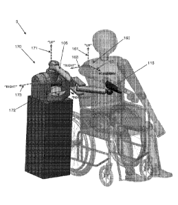
Additionally, Figs. 2 and 3 show a coordinate reference frame 160 for the
patient (consisting of an up axis 161, a forward axis 162 and a right axis
163), as
well as a coordinate reference frame 170 for the robotic device 5 (consisting
of an
up axis 171, a forward axis 172 and a right axis 173). The locations and
orientations of these reference frames 160, 170 defines a kinematic
relationship
between (i) the robotic device 5 and its links 105, 110, and (ii) the patient
and
their limb: the robotic device 5 is designed such that its motions mimic those
of
the patient, in that a given motion of the patient's endpoint in the reference
frame
Date Recue/Date Received 2022-03-07
- 27 -
160 of the patient will be matched by a generally similar motion of the
device's
endpoint in the reference frame 170 of robotic device 5. This relationship is
important to the definition of many of the innovative aspects of the device,
as
shown below.
Before further explaining this concept, it is helpful to provide some
terminology. The "patient reference frame" (or PRF) 160 and the "device
reference frame" (or DRF) 170, as used here, are located and oriented by
constant
physical characteristics of the patient and device. As shown in Figs. 2 and 3,
the
origin of the PRF 160 is defined at the base of the patient's limb which is
coupled
to the robotic device, and is considered fixed in space. The "up" vector 161,
which is treated as a "Z" vector in a right-handed coordinate system, is
defined to
point from this origin in the commonly accepted "up" direction (against the
direction of gravity). The "forward" vector 162 is likewise defined in the
commonly accepted "forward" direction, in front of the patient. More
precisely, it
is treated as a "Y" vector in a right-handed coordinate system, and is defined
as
the component of the vector pointing from the origin to the center of the
limb's
workspace which is perpendicular to the "up" vector. Finally, the "right"
vector
163 points to the right of the patient. Rigorously defined, it is treated as
an "X"
vector in a right-handed coordinate system, and is consequently defined by the
other two vectors. Thus, a reference frame 160 is defined for the patient
which is
located and oriented entirely by constant physical characteristics and
features.
While this coordinate frame definition has been executed in Figs. 2 and 3 for
a
patient's arm, this definition method can easily be extended to other limbs,
such
as a leg.
A similar reference frame is defined for the robotic device. The origin is
placed at the centroid of the base of the robotic device 5, which must also be
fixed
in space. The "forward" vector 172 is defined as the component of the vector
pointing from the origin to the geometric centroid of the device's workspace.
The
Date Recue/Date Received 2022-03-07
- 28 -
"up" vector 171 and the "right" vector 173 may be defined in arbitrary
directions,
so long as they meet the following conditions:
1) They are mutually perpendicular;
2) They are both perpendicular to the "forward" vector 172;
3) They meet the definition of a right-handed coordinate system wherein
the "up" vector 171 is treated as a Z vector, the "right" vector 173 is
treated as an
X vector, and the "forward" vector 172 is treated as a Y vector; and
4) Preferably, but not necessarily, the "up" vector 171 is oriented as
closely as possible to the commonly accepted "up" direction (against the
direction
of gravity).
In some cases, such as with the ReoGO arm rehabilitation system of
Motorika Medical Ltd. of Mount Laurel, New Jersey, USA, the aforementioned
condition "4)" cannot be satisfied because the device's "forward" vector
already
points in the generally accepted "up" direction; consequently, the "up" vector
may
be defined arbitrarily subject to the three previous conditions. This case is
further
detailed below.
When existing rehabilitation devices are separated into exoskeletal and
non-exoskeletal devices as per the description above, a further distinction
between
these two groups becomes apparent based on this definition of reference
frames.
In exoskeletal devices, the robotic device and the patient operate with their
reference frames (as defined above) oriented generally similarly: "up",
"right"
and "forward" correspond to generally the same directions for both the patient
and
the robotic device, with the misalignment between any pair of directions in
the
PRF and DRF respectively preferably no greater than 60 degrees (i.e. the
"forward" direction in the DRF will deviate no more than 60 degrees from the
"forward" direction in the PRF), and preferably no greater than 45 degrees.
Meanwhile, to date, a non-exoskeletal device in which the robotic device and
the
patient reference frames are generally oriented similarly in this way has not
been
Date Recue/Date Received 2022-03-07
- 29 -
created. Devices available today are oriented relative to the patient in a
number
of different ways, including the following:
- The DRF may be rotated 1800 around the "up" axis relative to
the PRF so
that the device "faces" towards the patient, or 90 , so that the device
"faces" perpendicular to the patient: for example, in the InMotion ARMTm
system of Interactive Motion Technologies of Watertown, Massachusetts,
USA; the HapticMaster haptic system of Moog Incorporated of East
Aurora, New York, USA; the DeXtremeTM arm of BioXtreme of Rehovot,
Israel; or the KINARM End-Point RobotTM of BKIN Technologies of
Kingston, Ontario, Canada. In the case of the DeXtremeTM arm, for
instance, the device is designed to be used while situated in front of the
patient. Its workspace, which is generally shaped like an acute segment of
a right cylinder radiating from the device's base, likewise faces towards
the patient. When a coordinate reference frame is generated for the
device's workspace as outlined above, the "forward" direction ¨ which
points from the centroid of the base of the device to the centroid of the
device's workspace ¨ will be found to point towards the patient.
Consequently, the device's reference frame is not oriented similarly to that
of the patient.
- Alternatively, the DRF may be rotated 90 about the "right" axis relative
to the PRF such that the device's "forward" axis is parallel to the patient's
"up" axis; or other combinations. One example is the ReoGOO arm
rehabilitation system of Motorika Medical Ltd of Mount Laurel, New
Jersey, USA, where the device's base sits underneath the patient's arm
undergoing rehabilitation, and its primary link extends up to the patient's
arm. Its workspace is generally conical, with the tip of the cone located at
the centroid of the base of the device. When a coordinate reference frame
is generated for the device as outlined above, the "forward" vector of the
Date Recue/Date Received 2022-03-07
- 30 -
device will be found to have the same direction as the "up" vector in the
patient's reference frame. Consequently, the device's reference frame is
not oriented similarly to that of the patient.
- Finally, devices like the ArmAssist device of Tecnalia0 of
Donostia-San
Sebastian, Spain may not have a definable DRF. The ArmAssist device is
a small mobile platform which is designed to sit on a tabletop in front of
the patient. The patient's arm is attached to the device, which then moves
around the tabletop to provide rehabilitative therapy. Since the ArmAssist
device is fully mobile, a fixed origin cannot be defined for it as per the
method outlined above, and it is not relevant to this discussion.
The robotic device of the present invention is the first non-exoskeletal
device which is designed to operate with its reference frame 170 oriented
generally similarly to the reference frame 160 of the patient. This innovation
allows the robotic device to leverage advantages that are otherwise limited to
exoskeletal devices, including:
= Reduced interference with the patient's line of sight or body, since the
robotic device does not need to sit in front of/to the side of the patient.
= More optimal position-torque relationships between patient and device,
since the moment arms between the device and patient endpoints and their
joints are directly proportional to one another, rather than inversely
proportional to one another as in other devices. For example, when the
device's links are extended, the patient's limb undergoing rehabilitation
will be generally extended as well. While the device is not able to exert as
much force at its endpoint as it can when the endpoint is closer to the
device's joints, the patient's force output capacity will be likewise
reduced. Similarly, when the patient's limb is contracted and the force
output is maximized, the device's endpoint will be closer to its joints, and
its endpoint output force capacity will be maximized.
Date Recue/Date Received 2022-03-07
- 31 -
= Better workspace overlap between the patient and the device, since the
device's links extend from its base in the same general direction that the
patient's limb extends from the body.
Like an exoskeletal device, the robotic device 5 generally mimics the
movements of the patient's limb, in that the endpoint of the device tracks the
patient's limb, and a given motion in the reference frame 160 of the patient
produces motion in a generally similar direction in the device's reference
frame
170. For example, if the patient moves their limb to the right in the
patient's
reference frame 160, the device's links will generally move to the right in
the
device's reference frame 170, as shown in Fig. 4. However, unlike an
exoskeletal
device, the individual links and joints of the robotic device do not
necessarily
mimic the motions of individual parts or joints of the patient's limb, even
though
the endpoint of the robotic device does track the patient's endpoint. As shown
in
Fig. 4, in the preferred embodiment, motions in front of the patient cause
both the
patient's limb and the links 105, 110 of robotic device 5 to extend; by
contrast, in
Fig. 4, motions to the far right of the patient cause the patient's limb to
straighten
while the links 105, 110 of the robotic device 5 bend. By operating without
this
constraint (i.e., that the individual links and joints of the robotic device
do not
necessarily mimic the motions of the individual parts or joints of the
patient's
limb), the robotic device 5 avoids many of the weaknesses inherent in
exoskeletal
devices, particularly the bulk, complexity, cost and setup time associated
with
directly replicating the kinematics of a limb.
Because of the need for this distinction between the robotic device of the
present invention and exoskeletal devices (i.e., that a relationship cannot
easily be
defined between the patient's limb and the links of the robotic device), it is
necessary to define the relationship between the robotic device and the
patient as
a function of the bases, endpoints and orientations of the robotic device and
the
patient. By defining device and patient reference frames in this manner, the
Date Recue/Date Received 2022-03-07
- 32 -
previous statement that "the robotic device 5 is designed such that its
motions
mimic those of the patient, in that a given motion of the patient's endpoint
in the
reference frame 160 of the patient will be matched by a generally similar
motion
of the device's endpoint in the reference frame 170 of robotic device 5" is
satisfied only when the robotic device 5 is oriented relative to the patient
as
described herein.
A series of simple logical tests have been developed to aid in determining
whether a device meets the criteria outlined above. For these tests, the
device is
assumed to be in its typical operating position and configuration relative to
the
patient, and a PRF is defined for the patient's limb undergoing rehabilitation
as
described above.
1) Is the device an exoskeletal rehabilitation device, as defined previously?
a. YES: Device does not meet criteria ¨ criteria are only applicable to
non-exoskeletal devices.
b. NO: Continue.
2) Can an origin that is fixed relative to the world reference frame and
located at the centroid of the base of the device be defined?
a. YES: Continue.
b. NO: Device does not meet criteria ¨ criteria are not applicable to
mobile devices.
3) Consider the device's workspace, and find the geometric centroid of that
workspace. Can a "forward" or Y vector be defined between the
geometric centroid of the device's workspace and the device's origin?
a. YES: Continue.
b. NO: Device does not meet criteria.
4) Can the "up"/Z vector and the "right"/X vector be defined as outlined
above relative to the forward vector?
a. YES: Continue.
Date Recue/Date Received 2022-03-07
- 33 -
b. NO: Device does not meet criteria ¨ it is likely designed for a
significantly different rehabilitation paradigm than the device
disclosed here.
5) Are the workspaces of the device and patient oriented generally similarly,
in that the "right"/X, "forward"/Y and "up"/Z vectors of both coordinate
reference frames have generally the same direction, with a deviation of
less than a selected number of degrees between any pair of vectors? (In the
preferred embodiment, this is preferably less than 60 degrees, and more
preferably less than 45 degrees.)
a. YES: Continue.
b. NO: The device does not meet the criteria outlined ¨ it is
positioned differently relative to the patient than the device
outlined here.
6) Are motions of the patient's endpoint mimicked or tracked by similar
motions of the device's endpoint?
a. YES: The device meets the criteria outlined.
b. NO: The device does not meet the criteria outlined.
To date, no device with more than 2 degrees of freedom, other than the system
described here, has been found that successfully passes this series of tests.
Stated another way, generally similar orientation between the patient and
the device can be examined by identifying a "forward" direction for both the
user
and the device. In the patient's case, the "forward" direction can be defined
as the
general direction from the base of the patient's arm undergoing
rehabilitation,
along the patient's limb, towards the patient's endpoint when it is at the
position
most commonly accessed during use of the device. In the device's case, the
"forward" direction can be defined as the general direction from the base of
the
device, along the device's links, towards the device's endpoint when it is at
the
position most commonly accessed during use of the device. If the "forward"
Date Recue/Date Received 2022-03-07
- 34 -
direction of the device and "forward" direction of the patient are generally
parallel
(e.g., preferably with less than 60 degrees of deviation, and more preferably
with
less than 45 degrees of deviation), then the device and the user can be said
to be
generally similarly oriented.
General Location Of System
One preferred embodiment of the present invention is shown in Figs. 3
and 4, where the robotic device 5 is positioned to the side of, and slightly
behind,
the patient (in this case, with the axis 125 of the joint J1 behind, or
coincident to,
the patient's coronal plane). In this embodiment, the reference frame 170 of
the
robotic device 5 and the reference frame 160 of the patient are oriented
generally
similarly, as described above. The robotic device 5 is kept out of the
patient's
workspace and line of sight, making it both physically and visually
unobtrusive.
The workspaces of the robotic device and patient overlap to a high degree. The
range of motion allowed by this positioning is still quite large, as shown in
Fig. 4,
and approaches or exceeds that allowed by high-DOF exoskeletal systems.
It should be noted that while this arrangement (i.e., with the robotic device
5 positioned to the side of, and slightly behind, the patient) has been found
to be
preferable for certain rehabilitative therapies, there are other embodiments
in
which the robotic device 5 is positioned differently relative to the patient
which
may be better suited to other applications, such as use as a haptic
input/control
device, or other rehabilitative activities. For example, in the case of
advanced-
stage arm rehabilitation, in situations where the patient is reaching up and
away
from the device, it may prove optimal to place the robotic device slightly in
front
of the patient.
Date Recue/Date Received 2022-03-07
- 35 -
Link Stacking Order
Looking next at Figs. 5A, 5B and 5C, several novel implementations of
the system are shown wherein the device's links 105, 110 are ordered in
different
directions to facilitate different activities. By way of example but not
limitation,
Fig. 5A shows a configuration referred to as the "stacked-down" configuration,
in
which the outer link 110 of the robotic device 5 is attached to the underside
of the
inner link 105 of the robotic device 5, allowing the device to reach from
above the
patient, downwards, to their limb (attached via coupling element 115). Fig. 5C
shows a configuration referred to as the "stacked-up" configuration, in which
the
outer link 110 of the robotic device 5 is attached to the top side of inner
link 105
of the robotic device 5, allowing the device to reach from below the patient,
upwards, to their limb (attached via coupling element 115). Both
implementations may prove optimal in different situations. The "stacked-down"
variant is less likely to interfere with the patient's arm during
rehabilitation
activity because of its position above the patient's workspace, and may prove
more useful for high-functioning rehabilitation patients who require expanded
workspace. Conversely, the "stacked-up" variant is better able to support a
patient's arm, and is less likely to interfere with the patient's visual
workspace; it
is better suited for low-functioning patients. Fig. 5B shows a configuration
referred to as the "stacked flat" configuration, in which the outer link 110
of the
robotic device 5 is attached to the bottom side of inner link 105 of the
robotic
device 5, and coupling element 115 is attached to the top side of outer link
110,
allowing the device to reach the patient so that the forearm of the patient is
approximately flat with inner link 105.
Cabled Differential, With Alternative Configurations
Fig. 6 illustrates an important aspect of the present invention, i.e., the use
of a cabled differential (see, for example, U.S. Patent No. 4,903,536) in a
Date Recue/Date Received 2022-03-07
- 36 -
rehabilitation device. The preferred embodiment of the robotic device 5
comprises three revolute joints J1, J2 and J3, implemented in a pitch-yaw-yaw
configuration (Fig. 1), with the first two joints (i.e., J1 and J2) linked in
a cabled
differential as shown in Fig. 6. As shown in Fig. 6, the use of a cabled
differential
allows a motor that would normally be mounted on a higher-level kinematic
frame to be moved down to a lower-level frame. For example, in the preferred
embodiment shown in Fig. 6, the motors 500 that cause rotation about joint J1
and
joint J2 are moved from the aforementioned joint J1 kinematic frame (which
rotates about the axis 125 of joint J1 down to the aforementioned ground
kinematic frame (the ground frame; collocated with base 100 in Fig. 1). This
significantly reduces the inertia that the motors 500 are required to move,
which
improves the performance of the robotic device and reduces its cost by
permitting
smaller motors 500 to be used. Although this is implemented in the preferred
embodiment at the base of the robotic device, the principle behind this design
is
valid anywhere along a device's kinematic chain. This is a particularly
important
innovation in the context of a rehabilitation device because of its ability to
reduce
the device's cost, which must be kept low to ensure the commercial success of
the
device. This configuration also allows the exclusive use of rotary joints
(instead
of prismatic joints), which greatly simplifies the design of the device. Lower
inertia also improves the safety of the device by lowering the momentum of the
device. Finally, this innovation also maximizes usability by allowing the
visual
bulk of the device to be shifted away from the patient's line of sight towards
the
base of the device. While this concept is executed as part of a rehabilitation
device with three degrees of freedom in the preferred embodiment, it is
clearly
applicable to other rehabilitation devices with as few as two degrees of
freedom.
Furthermore, in the preferred embodiment shown in Figs. 1 and 6, the
implementation of a cabled differential with the input and output axes (i.e.,
the
axes of input pulleys 505 and output pulley 540) both perpendicular to the
distal
Date Recue/Date Received 2022-03-07
- 37 -
link axis (i.e., the axis along inner link 105) provides the benefits of a
cable
differential while allowing the unique pitch-yaw kinematic arrangement that
makes this device so well suited to rehabilitation use. Previous
implementations
of cabled differentials have either been arranged in a pitch-roll
configuration such
as in the Barrett WAM product of Barrett Technology, Inc. of Newton, MA as
shown at 700 in Fig. 8C, or in a roll-pitch configuration such as in the
Barrett
WAM wrist product as shown at 720 in Fig. 8B. In both of these implementations
(i.e., the pitch-roll configuration 700 of Fig. 8C and the roll-pitch
configuration
720 of Fig. 8B), either the distal link (i.e., the link beyond the
differential in the
kinematic chain) or the proximal link (i.e., the link before the differential
in the
kinematic chain) is permanently coaxial with one of the two differential
rotational
axes. In the case of the pitch-roll configuration 700 of Fig. 8C, the outer
link 710
is always coaxial to the differential output axis 705; in the roll-pitch
configuration
720 of Fig. 8B, the inner link 725 is always coaxial to the differential input
axis
730.
To date, however, the cabled differential has not been used in a
configuration where neither of the differential axes is coaxial to one of the
links.
This configuration has been successfully implemented in the preferred
embodiment of the present invention, as seen in both Fig. 6 (see the pitch-yaw
configuration of joints J1 and J2 relative to the inner link of the device
105) and in
Fig. 8A, where the novel pitch-yaw configuration 740 is shown. This new
implementation of the cable differential enables innovative kinematic
configurations like that used in the present invention.
Bimanual Multi-Dimensional Rehabilitation Exercises And Device Design
Fig. 9 shows how the preferred embodiment of the robotic device 5 is
optimal for the purposes of switching from right-handed to left-handed use.
The
robotic device 5 is essentially symmetric across a plane parallel to the
patient's
Date Recue/Date Received 2022-03-07
- 38 -
midsagittal plane and coincident with the axis 130 of joint J2. By simply
ensuring
that the range of joint J2 is symmetric about the previously described plane,
and
enabling the outer link 110 to be reversed about the axis 135 of joint J3 such
that
its range of motion is symmetric about the previously described plane in
either
position, the device's chirality can easily be reversed, enabling it to be
used on
either the right side or left side of the patient's body as seen in Fig. 9.
Finally, Fig. 10 illustrates how the innate symmetry and reversible
chirality of robotic device 5 combine with its unique working
position/orientation
and small size to allow two units of the robotic device to be used
simultaneously
for three-dimensional bimanual rehabilitation. In bimanual rehabilitation, the
afflicted limb is paired with a non-afflicted limb in rehabilitation
activities,
including cooperative tasks, such as using both limbs to lift an object; and
instructive tasks, where the healthy limb "drives" the afflicted limb. The
value of
bimanual rehabilitation (particularly in the context of rehabilitation from a
neuromuscular injury such as a stroke, which can make execution of
neurologically complex tasks like coordinated movement between limbs on
opposite sides of the body exceedingly difficult) was theorized as early as
1951,
and has gained significant traction over the past 20 years. See "Bimanual
Training After Stroke: Are Two Hands Better Than One?" Rose, Dorian K. and
Winstein, Carolee J. Topics in Stroke Rehabilitation; 2004 Fall; 11(4): 20-30.
Robotic rehabilitation devices are extremely well suited to this type of
therapy,
due to their ability to precisely control the motion of the patient's limbs
and
coordinate with other rehabilitation devices. In an exemplary implementation
shown in Fig. 10, a first robotic device 5 is connected to the patient's
afflicted
right arm, while a second robotic device 5 is connected to a more functional
left
arm. The robotic devices are linked to each other through some type of common
controller (e.g., as seen in Fig. 12, an external controller 578 that
communicates
with the onboard controllers of both robotic devices 5, while facilitating
Date Recue/Date Received 2022-03-07
- 39 -
communication between the two devices ), which coordinates the rehabilitation
therapy. While this example is demonstrated using images of the preferred
embodiment of the robotic device, it may be understood that the essential
concept
of bimanual rehabilitation may be implemented with any variety of devices,
even
if those devices are dissimilar. However, there are significant advantages to
using
two similar robotic devices 5 for bimanual rehabilitation, which are disclosed
below, and which lead to a novel method for bimanual rehabilitation.
The robotic device 5 described here is the first non-planar rehabilitation
device to be purpose-designed for this type of dual-device, simultaneous use
in a
three-dimensional bimanual system. As described earlier, the robotic device's
innate symmetry allows its chirality to be easily reversed, allowing the same
robotic device design to be used for rehabilitation of both right and left
limbs.
Furthermore, the device's small footprint facilitates simultaneous use of two
systems, as shown in Fig. 10. While other devices, such as the ArmeoTmPower
system of Hocoma AG of Volketswil, Switzerland, are similarly reversible, the
size of these systems and their position relative to the patient precludes
their use
in a bimanual rehabilitation system, since the bases of the two systems would
interfere. There are also some devices that have been deliberately designed
for
bimanual rehabilitation, such as the KINARM ExoskeletonTM and EndPointTM
robots of BKIN Technologies of Kingston, Ontario, Canada. However, as
mentioned above, these devices are deliberately limited to planar (two-
dimensional) rehabilitative therapies, significantly impacting their utility
for
patients.
There exists one known example of a system that is nominally capable of
performing limited 3-dimensional bimanual rehabilitation therapies with only
unimanual actuation, i.e., the 3rd-generation Mirror-Image Motion Enabler
(MIME) rehabilitation robot, developed as a collaborative project between the
Department of Veterans Affairs and Stanford University in 1999. See
Date Recue/Date Received 2022-03-07
- 40 -
"Development of robots for rehabilitation therapy: The Palo Alto VA/Stanford
experience." Burgar et. al. Journal of Rehabilitation Research and
Development.
Vol. 37 No. 6, Nov/Dec 2000, pp. 663-673. The 3rd-generation MIME robot
consists of a PUMA-560 industrial robot affixed to the patient's afflicted
limb,
and a passive six-axis MicroScribe digitizer affixed to a splint, which is in
turn
coupled to the patient's healthy limb. In the system's bimanual mode, motions
of
the healthy limb are detected by the digitizer and passed to the robotic arm,
which
moves the afflicted limb such that its motions mirror those of the healthy
limb.
While this system can execute a limited set of bimanual rehabilitation
therapies, it
is fundamentally limited by the unidirectional flow of information within the
system: information can be passed from the healthy limb to the afflicted limb,
but
not back from the afflicted limb to the healthy limb, since the digitizer is
passive
and does not have motors or other mechanisms with which to exert forces on the
patient's healthy limb.
In the implementation described herein, the use of two similar, active
robotic devices 5 ¨ in the preferred implementation, with similar kinematics,
joint
ranges, force output limits and static and dynamic performance characteristics
¨
enables bidirectional information flow (i.e., bidirectional informational flow
wherein both devices send, receive and respond to information from the other
device), creating a bimanual rehabilitation system that is capable of
monitoring
the position of both the afflicted and healthy limbs, moving the patient's
afflicted
limb in three dimensions and potentially controlling its orientation
simultaneously, and optionally providing simultaneous force feedback, support
or
other force inputs to the healthy limb. For example, the robotic device
connected
to the patient's healthy limb can be used to "drive" the robotic device
connected
to the patient's afflicted limb, while simultaneously supporting the healthy
limb to
prevent fatigue, and providing force feedback to the healthy limb as required
by
the therapy. In this respect it has been found that the cable drives used in
the
Date Recue/Date Received 2022-03-07
- 41 -
preferred implementation of the present invention are particularly well suited
to
this type of use, because of the high mechanical bandwidth of cable drive
transmissions; however, alternative embodiments could be implemented using
alternative mechanical drive systems. Regardless of specific implementation,
this
bidirectional information flow ¨ when executed between two similar devices
with
the facilitating characteristics described here ¨ allows the device to be used
for a
far wider range of three-dimensional bimanual rehabilitative therapies than
prior
art systems and enables the method disclosed herein.
Additional Applications For The Present Invention
In the preceding description, the present invention is discussed in the
context of its application for a rehabilitation device. However, it will be
appreciated that the present invention may be utilized in other applications,
such
as applications requiring high-fidelity force feedback. By way of example but
not
limitation, these applications may include use as an input/haptic feedback
device
for electronic games, as a controller for other mechanical devices, such as
industrial robotic arms or construction machines, or as a device for sensing
position, i.e., as a digitizer or coordinate measuring device.
Modifications Of The Preferred Embodiments
It should be understood that many additional changes in the details,
materials, steps and arrangements of parts, which have been herein described
and
illustrated in order to explain the nature of the present invention, may be
made by
those skilled in the art while still remaining within the principles and scope
of the
invention.
Date Recue/Date Received 2022-03-07