Note: Descriptions are shown in the official language in which they were submitted.
CA 02957859 2017-02-10
WO 2016/058989 PCT/EP2015/073563
-1-
Apparatus and Method for Cutting out a Vehicle Glazing Panel
The present invention relates to a vehicle glazing panel cut out apparatus and
method.
The invention particularly relates to a technique using a cutting line or
filament such as a
wire or synthetic fibre line in order to effect release of the glazing panel,
such as a
windscreen, from its mounted position in the vehicle windscreen frame. The
technique and
cut-out tool of the present invention is also applicable to use on other
bonded glazing
panels.
Prior art is known which uses winder spools for winding the cutting line or
wire mounted
on a single tool in order to effect cut out of a vehicle windscreen or side
glass. Exemplary
arrangements are disclosed in, for example US7618023 W02006030212
W02012069804.
An improved technique and apparatus have now been devised.
According to a first aspect, the present invention provides a winder unit for
use with a
cutting line or filament (such as a wire) in cutting out a vehicle glazing
panel, the winder
unit having:
at least one winder spool for winding cutting filament;
a mount for mounting the unit;
wherein the winder spool is movable relative to the mount between first and
second operational positions.
It is preferred that the winder spool is movable relative to the mount between
first and
second operational positions, such that the rotational axis of the winder
spool is movable
(preferably angularly for example by being tilt-able) relative to the mount
between first
and second positions.
CA 02957859 2017-02-10
WO 2016/058989 PCT/EP2015/073563
-2-
This may be achieved by means of the winder spool being arcuately, hinge,
pivot, or tilt,
movable relative to the mount between first and second operational positions.
It is preferred that the unit includes at least one filament or line guide
spaced from the
winder spool, wherein the winder spool and filament or line guide are movable
relative to
the mount between first and second operational positions.
In certain embodiments it may be preferred that the winder spool and filament
guide are
mounted to be moveable together (in unison) between first and second
operational
positions. To this end they may be mounted for movement on a common movable
component such as a platform or deck.
In certain embodiments it may be preferred that the unit comprises two winder
spools, both
being movable relative to the mount between first and second operational
positions.
Beneficially, in such an embodiment, the winder spools may be mounted to be
moveable
together between first and second operational positions.
It is preferred that the unit includes at least one filament or line guide
spaced from the one
or more spools, which filament or line guide comprises a rotatable guide such
as a pulley
wheel.
In one embodiment it is preferred that the unit comprises two spaced winder
spools and a
respective two filament or line guides spaced one at either side of a
respective spool , the
spools and guides being movable (preferably together) relative to the mount
between first
and second operational positions.
It is preferred that securing means is provided for securing the winder spool
(and also
preferably the line guide, where present) in fixed position relative to the
mount.
Beneficially, the securing means is arranged to secure the spool relative to
the mount in the
first and second positions and one or more positions intermediate the first
and second
positions.
CA 02957859 2017-02-10
WO 2016/058989 PCT/EP2015/073563
-3-
Beneficially, the unit further comprises at least one filament or line guide
spaced from the
winder spool, wherein the winder spool and filament guide are movable relative
to the
mount between first and second operational positions and wherein the same
securing
means secures both the winder spool and filament guide relative to the mount.
In certain embodiments it is preferred that the mount comprises a suction
mount.
In an alternative definition, the invention provides winder unit for use with
a cutting line or
filament (such as a wire) in cutting out a vehicle glazing panel, the winder
unit having:
at least one winder spool for winding cutting filament;
at least one filament or line guide spaced from the winder spool;
a mount for mounting the unit;
wherein the winder spool and filament or line guide are mounted to be movable
in
unison (preferably angularly) relative to the mount between first and second
operational positions.
The invention will now be further described, in a specific embodiment, by way
of example
only and with reference to the accompanying drawings, in which:
Figure 1 is a schematic perspective view of apparatus in accordance with the
invention in a
first position or configuration;
Figure 2 is a schematic perspective view of the apparatus of figure 1 in a
second position
or configuration;
CA 02957859 2017-02-10
WO 2016/058989 PCT/EP2015/073563
-4-
Figure 3 is a plan view of the apparatus of figure 1;
Figures 4A and 4B are side views of the apparatus in different configurations;
Figure 5 is a side view showing the apparatus in use.
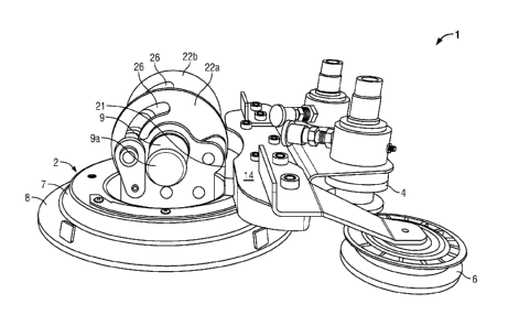
Referring to the drawings, the cut out apparatus comprises a winder unit 1 for
use in
winding a cutting filament such as a cutting wire or fibre line for use in
cutting out a
vehicle glazing panel. Techniques for winding cutting filaments are known in
the art. The
unit 1 as shown has a single suction mount 2 but it will be readily
appreciated that plural
suction mounts may be utilised. Mounted on-board the suction mount 2 are a
pair of
spaced winder spools 3, 4 and pair of spaced rotatably mounted guide pulley
wheels 5, 6.
The suction mount 2 enables the wire winder unit 1 to be releasably and
securely mounted
to the vehicle windscreen (typically on the inside of the vehicle). The winder
spools 3, 4
are spaced to be positioned one on either side of a diameter line of the
suction mount.
The suction mount 2 comprises a rigid plastics cup moulding 7 and an
underlaying flexible
rubber sucker membrane 8. The flexible rubber sucker membrane 8 extends beyond
the
periphery of the rigid plastics cup moulding 7 in order to enhance the suction
capability of
the suction mount 2. A manually actuatable suction pump 9 enables consistent
suction to
be applied and released. Using the pump piston actuator 9a.
The winder spools 3, 4 and also the guide pulley wheels 5,6 are provided on
board a
winder spool mounting deck 14 which is tilt-ably mounted to the to the suction
mount 2.
The deck 14 carries the pair of winding spools 3, 4 in side by side
relationship such that the
wire receiving reel 4a is underslung below the deck 14. The winder spools 3, 4
are
connected to axial winding shafts which are supported in bearings provided on
the deck 14.
The winder spools 3, 4 are driven axially rotationally either manually via a
hand winder or
by means of a mechanical actuator such as a motorised winding or winching
tool. Drive
bosses 19 are provided with female sockets (square bores) for receiving the
male driving
tool. Positioned outwardly of the winding spools are respective wire guide
pulley wheels
5, 6 of low friction plastics material. The pulley wheels are mounted to be
rotatable about
CA 02957859 2017-02-10
WO 2016/058989 PCT/EP2015/073563
-5-
respective rotational axes. The guide pulleys rotate as the cutting wire is
drawn tangentially
across the pulleys as will be described. The winder spools 3, 4 are held to
rotate in one
direction only (each in opposite senses) by respective ratchet mechanisms 13.
Each
mechanism includes ratchet override permitting prior tightened wire to be
slackened, or
unwound (reverse wound) the ratchets can be overridden by pulling out the
ratchet release
knobs 13a.
The guide pulley wheels 5, 6 are mounted to the deck 14 by means of pulley
wheel
mounting arms 12. Because both the guide pulley wheels 5,6 and the winder
spools 3, 4
are both mounted to the deck and the deck 14 is tilt-ably/pivotably mounted to
the suction
mount 2, the spools 3,4 and pulleys 5,6 are movable in unison to tilt upwardly
or
downwardly relative to the suction mount 2. This enables the position of guide
pulley
wheels 5, 6 and the spools 3, 4 to be altered dependent upon the degree of
curvature of the
screen upon which the device is being used. Different degrees of tilting
orientation are
shown in figures 4A and 4B. Encompassed within the broad ambit of the idea of
the pulley
wheels 5, 6 and the spools 3, 4 being movable in this fashion is any means by
which the
spools 3, 4 and the wheels 5, 6 can be re-orientated either in unison or
independently from
one operational position to another in which the rotational axis of either is
changed with
respect to the glazing panel to which the unit is mounted. There are however
perceived to
be benefits in an arrangement in which the spools 3, 4 and pulleys 5, 6 are
moveable in
unison.
Importantly means is provided for securing the pulleys 5, 6 and spools in the
various
angular orientations with respect to the suction mount 2. In the arrangement
shown this is
achieved by the deck 14 being mounted by means of a bracket 21 to a pair of
rotatable
wings 22a 22b. By means of rotating the wings about the axis of the pump 9,
the deck 14
(and the spools 3, 4 and pulleys 5, 6 mounted thereto) arcuately move
rotatably about an
axis defined along the pump 9. The securing means comprises screw clamps 25
which
screw against the wings 22a, 22b. The shaft of the screws 25 passes through a
keyway 26
to permit angular tilting or arcuate movement of the deck 14 and securing in
position. In
any event the precise mechanism of the hinging and the securing means is not
essential to
the invention, save to the extent that such means are provided. The In the
embodiment
CA 02957859 2017-02-10
WO 2016/058989 PCT/EP2015/073563
-6-
shown on figures 4 and 5 an alternative hinging mechanism 22 is shown
schematically. It
is beneficial that the securing mechanism allows the pulleys and spools 3, 4
to be secured
in any one of a plurality of desired selected positions.
In use, the arrangement can be used in a generally similar manner to the
winder unit
described in figures 9 to 1 of W02006030212. Initially a flexible cutting wire
is looped
around the outside of a windscreen glazing panel to lie peripherally adjacent
the bonding
bead (typically a polyurethane bonding bead) which is sandwiched between the
glazing
panel and the support frame of the vehicle. Opposed ends of the cutting wire
are fed
through a pierced channel made through the bonding bead and the free ends are
then each
wound around a separate winder spool of the winder unit.
The glazing panel can as such be removed using a wire and the winder unit 1
only (no
additional guide is required).
An important improvement over the prior art is that because both the spools
3,4 and the
pulleys can hinge, tilt or otherwise arcuately re-orientate relative to the
suction mount 2,
glazing panels of higher degree of curvature such as for example found on
coaches or
busses can be accommodated for removal using cutting filament techniques. This
is shown
schematically in figure 5. The design allows the cutting line or filament 32
to be pulled in
the correct direction whilst the suction mount 2 is fitted to a spaced portion
of the very
curved glazing panel 30.