Note: Descriptions are shown in the official language in which they were submitted.
CA 02957879 2017-02-13
DISK BENDING SHEAR TESTING AND SYSTEM
BACKGROUND OF THE INVENTION
Composite structures, such as composite laminate structures, are used in a
variety of
industries. For example, the aircraft industry uses composite laminate
structures for
aircraft body panels, blades, and other elements. Composite laminate
structures can
experience structural defects in the form of delamination, voids, impact
damage, marcels,
ply wrinkles, and other defects during a lifetime of the composite laminate
structure. A
sample of a composite laminate structure can be tested to approximate shear
characteristics of the composite laminate structure.
SUMMARY OF THE INVENTION
This disclosure describes methods and systems for disk bending shear testing
samples, for
example, laminate composite material samples.
In some aspects, a method for determining a shear property of a sample
includes
supporting a sample at three or more separate support locations about a
periphery of a
first surface of the sample in a testing fixture, the sample including a
second surface
separated from the first surface by a thickness. The method further includes
applying a
load on the second surface of the sample with a load applicator in a direction
substantially
orthogonal to the second surface of the sample, measuring shear testing data
of the
sample with a controller in response to applying the load, and determining a
shear
property of the sample from the measured shear testing data.
This, and other aspects, can include one or more of the following features.
The three or
more separate support locations can be equidistantly disposed about the
periphery of the
first surface. Supporting the sample at three or more separate support
locations about a
periphery of the first surface can include supporting the sample with three or
more clamps
at the three or more separate support locations about the periphery of the
first surface.
Supporting the sample at three or more separate support locations can include
supporting
the sample continuously about the entire periphery of the first surface.
Supporting the
sample continuously about the entire periphery of the first surface can
include supporting
the sample with a ring-shaped support structure about the periphery of the
first surface.
Determining a shear property of the sample from the measured shear testing
data can
include performing a data analysis on the shear testing data to determine the
shear
1
CA 02957879 2017-02-13
property. Determining a shear property' of the sample from the shear testing
data can
include determining a shear stress of the sample. Applying a load on the
second surface
of the sample can include applying one of static loading, fatigue loading, or
impact
loading on the second surface of the sample. The sample can be rotationally
symmetric
about an axis that is orthogonal to the first surface. The sample can be
axisymmetric
about the axis. The load can be applied substantially along the axis. The
sample may not
be rotationally symmetric about the axis that is orthogonal to the first
surface. The
sample can have a surface profile of an irregular shape. The sample can
include a
laminate structure. The sample can include a composite laminate sample,
wherein at least
two laminate layers of the composite laminate sample are oriented in different
directions.
The method can include disposing, prior to applying the load on the second
surface of the
sample, at least one delamination insert between adjacent layers of the
laminate structure
to delaminate the adjacent layers of the laminate structure. The sample can
include a bore
hole in at least one of the first surface or the second surface of the sample.
Applying a
load on the second surface of the sample with a load applicator can include
distributing
the applied load over the second surface of the sample with a pad disposed
between the
sample and the load applicator. Determining a shear property of the sample
from the
shear testing data can include determining a stress state of the sample.
In some aspects of the disclosure, a system includes a support structure
supporting a
sample at three or more separate support locations about a periphery of a
first surface of
the sample, the sample including a second surface separated from the first
surface by a
thickness. The system includes a load applicator configured to apply a load on
the second
surface of the sample in a direction substantially orthogonal to the second
surface of the
sample, and a controller configured to control the load applied by the load
applicator and
measure shear testing data of the sample in response to the applied load.
This, and other aspects, can include one or more of the following features.
The three or
more separate support locations can be equidistantly disposed about the
periphery of the
first surface. The support structure can include three or more clamps
positioned at the
three or more separate support locations about the periphery of the first
surface to support
the sample. The support structure can include a ring-shaped support structure
positioned
about the periphery of the first surface of the sample, the ring-shaped
support structure
configured to support the sample continuously about the entire periphery of
the first
surface. The system can include a pad disposed between the sample and the load
2
applicator to distribute the load applied on the second surface. The sample
can include a bore
hole in the first surface of the sample. The sample can include a composite
laminate structure.
The sample can include a composite laminate sample, wherein at least two
laminate layers of the
composite laminate sample are oriented in different directions. The sample can
include at least
one insert between adjacent layers of the laminate structure to delaminate the
adjacent layers of
the laminate structure. The sample can be rotationally symmetric about an axis
that is orthogonal
to the first surface. The sample can be axisymmetric about the axis. The
sample may not be
rotationally symmetric about the axis that is orthogonal to the first surface.
The sample can have
a surface profile of an irregular shape.
In some aspects of the disclosure, a method for determining shear properties
of a sample includes
supporting a sample continuously about an entire periphery of a first surface
of the sample in a
testing fixture, the sample including a second surface separated from the
first surface by a
thickness. The method includes applying a load on the second surface of the
sample with a load
applicator in a direction substantially orthogonal to the second surface,
measuring, with a
controller, shear testing data of the sample in response to applying the load,
and determining
shear properties of the sample from the shear testing data.
There is disclosed a method for determining a shear property of a sample, the
method
comprising: supporting the sample at three or more separate support locations
about a periphery
of a first surface of the sample in a testing fixture, the sample comprising a
second surface
separated from the first surface by a thickness, and wherein supporting the
sample at three or
more separate support locations about a periphery of the first surface
comprises supporting the
sample with three or more clamps at the three or more separate support
locations about the
periphery of the first surface, each clamp comprising a lower clamp member
having a first
chamfered surface and an upper clamp member having a second chamfered surface;
applying a
load on the second surface of the sample with a load applicator in a direction
orthogonal to the
second surface of the sample; measuring, with a controller, shear testing data
of the sample in
response to applying the load; and determining, with the controller, a shear
property of the
sample from the measured shear testing data.
3
CA 2957879 2019-11-22
The details of one or more implementations of the subject matter described in
this disclosure are
set forth in the accompanying drawings and the description below. Other
features, aspects, and
advantages of the subject matter will become apparent from the description and
the drawings.
BRIEF DESCRIPTION OF THE DRAWINGS
For a more complete understanding of the features and advantages of the
present invention,
reference is now made to the detailed description of the invention along with
the accompanying
figures and in which:
FIG. 1 is a partial schematic and partial cutaway perspective view of an
example shear testing
system.
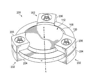
FIG. 2 is a quarter-sectional cutaway perspective view of an example support
structure and
sample for a shear testing system.
3a
CA 2957879 2019-11-22
CA 02957879 2017-02-13
FIG. 3 is a quarter-sectional cutaway perspective view of an example support
structure
and sample for a shear testing system.
FIG. 4A is a side view of an example sample for a shear testing system. FIGS.
4B-4F are
partial cross-sectional cutaway side views of example samples for a shear
testing system.
FIG. 5 is an example flowchart for determining a shear property of a sample.
Like reference numbers and designations in the various drawings indicate like
elements.
DETAILED DESCRIPTION OF THE INVENTION
Illustrative embodiments of the system of the present application are
described below. In
the interest of clarity, not all features of an actual implementation are
described in this
specification. It will of course be appreciated that in the development of any
such actual
embodiment, numerous implementation-specific decisions must be made to achieve
the
developer's specific goals, such as compliance with system-related and
business-related
constraints, which will vary from one implementation to another. Moreover, it
will be
appreciated that such a development effort might be complex and time-consuming
but
would nevertheless be a routine undertaking for those of ordinary skill in the
art having
the benefit of this disclosure.
In the specification, reference may be made to the spatial relationships
between various
components and to the spatial orientation of various aspects of components as
the devices
are depicted in the attached drawings. However, as will be recognized by those
skilled in
the art after a complete reading of the present application, the devices,
members,
apparatuses, etc. described herein may be positioned in any desired
orientation. Thus, the
use of terms such as "above," "below," "upper," "lower," or other like terms
to describe a
spatial relationship between various components or to describe the spatial
orientation of
aspects of such components should be understood to describe a relative
relationship
between the components or a spatial orientation of aspects of such components,
respectively, as the device described herein may be oriented in any desired
direction.
This disclosure describes a testing system for shear testing a sample, such as
a composite
laminate specimen, by supporting the sample in the testing system with
distributed
support about a periphery of the sample, and applying a load on a surface of
the sample.
The distributed support can include rotationally symmetric support,
substantially even
distribution of support (e.g., about a periphery of a sample), axisymmetric
support (e.g.,
4
CA 02957879 2017-02-13
continuous support about an axis of the sample), and/or support otherwise
disposed to
distribute an applied load on a sample substantially evenly about the support.
In some
instances, the shape and/or surface profile of the sample is rotationally
symmetric about
an axis of the sample, such as a central axis of the sample. In this
disclosure, rotational
symmetry includes rotational symmetry to an order of two or three or more, up
to an
infinite order (e.g., axisymmetric symmetry, cylindrical symmetry). For
example, a
sample with a fifth order rotational symmetry can include a pentagon (e.g.,
pentagonal
prism), an eighth order rotational symmetry can include an octagon (e.g.,
octagonal
prism), and so on. The shape and/or surface profile of the sample can vary. In
some
instances, the sample can be axisymmetric, such as a cylindrical disk or other
axisymmetric shape. In some examples, the sample can include an elliptical
disk, or a
disk with a surface profile of an irregular shape.
The testing system can be used to determine a shear property of a sample, such
as
interlaminar shear strength or shear stress of a composite laminate specimen.
In some
instances, when a composite laminate structure is loaded under bending, the
structure
experiences interim inar shear stresses through a thickness of the composite
laminate
structure. Interlaminar shear strength can be determined, or at least
approximated, by
testing a sample in a testing system under loading, such as static, fatigue,
and/or impact
loading, measuring shear testing data of the sample, and determining shear
properties
(e.g., shear property data) of the sample.
Some conventional shear testing systems include a two-point-support, where a
laminate
(e.g., layered) test specimen is supported on two points, with a longitudinal
axis spanning
between the two support points. For example, some conventional shear testing
systems
test composite structures according to ASTM D2344 Short Beam Shear (SBS)
testing,
where a rectangular, unidirectional composite structure is tested under a two-
point-
support near each longitudinal end. This two-point-support can limit
evaluation of the
test specimen when exposed to a bending force, for example, such that shear
property
data is acquired only for a unidirectional laminar test specimen (e.g., layers
oriented at
zero degrees).
This disclosure describes an example testing system that supports (e.g.,
axisymmetrically
supports) a laminate sample at three or more locations of the sample when
exposed to an
applied load, and measures shear testing data of the sample, for example,
failure load,
loading point displacement, and/or other, to determine a shear property or
properties of
5
CA 02957879 2017-02-13
the sample. The three or more support locations can be distributed evenly
about the
sample, and can include continuous support (e.g., axisymmetric support) about
the
sample. In some implementations, the layers of the laminate sample can be
oriented at
the same or different degrees along the thickness of the sample. In some
examples of this
disclosure, the testing system determines shear properties (e.g., interlaminar
shear
strength, shear stress, and/or other characteristic) of a composite sample
that better
exemplifies a composite element of a rotorcraft, aircraft, vehicle, windmill,
turbine and/or
other structure as compared to a testing system with a two-point-support, as
described
above. This is accomplished, for example, because the determined shear
properties
reflect shear characteristics of the sample in several (i.e., more than one)
directions,
instead of just a single direction (e.g., in a unidirectional rectangular
sample). For
example, the sample can include layers oriented in several (i.e., more than
one) direction.
In some examples, determined shear properties of a composite laminate sample
that is
supported in a testing system of this disclosure more closely represents shear
properties of
an actual composite structure (e.g., blade) of a rotorcraft, aircraft,
vehicle, windmill,
turbine, energy equipment, sports equipment, and/or other.
FIG. 1 is a partial schematic perspective view of an example testing system
100.
The testing system 100 includes a support structure 102 to support a sample
108, a load
applicator 104 to apply a load on the sample 108, and a controller 106 to
control the
applied load and to measure shear testing data (e.g., failure load, loading
displacement) of
the sample 108. In some implementations, the controller and/or a data analysis
of the
shear testing data can determine a shear property or properties of the sample
108. The
support structure 102 supports a sample 108 within the testing system 100
about a
periphery of the sample 108, for example, by supporting a periphery of a first
(e.g.,
bottom) surface of the sample 108. The sample 108 has a first surface 110, a
second
surface 112, and a thickness 114 separating the first surface 110 and the
second surface
112. The first surface 110 is parallel to the second surface 112 in the
example testing
system 100 of FIG. 1; however, these surfaces can be oriented so that they are
not parallel
to each other. The example sample 108 is axisymmetric about an axis A-A that
is
orthogonal to the first surface 110. In the example system 100 of FIG. 1, the
sample 108
defines a cylindrical disk, where the axis A-A is aligned with the centers of
the first
surface 110 and second surface 112. The sample 108 can take a variety of
forms. For
example, the sample 108 can be another shape, such as an elliptical disk, a
rectangular
6
CA 02957879 2017-02-13
block, or other rotationally symmetric shape, such as pentagonal, hexagonal,
octagonal, or
other multi-faceted shapes.
The example support structure 102 includes a first support member 116 and a
second
support member 118 substantially surrounding the sample 108 about the first
surface 110
and second surface 112, respectively. In the example testing system 100 of
FIG. 1, the
first support member 116 and second support member 118 are substantially
cylindrical
with an opening in a center of each of the members 116 and 118. The first
support
member 116 includes a chamfered edge that engages the first surface 110 of the
sample
108 about the periphery (e.g., outer edge) of the first surface 110.
Similarly, the second
support member 118 includes a chamfered edge that engages the second surface
112 of
the sample 108 about the periphery (e.g., outer edge) of the second surface
112. A
centering member 120 (e.g., centering ring) between the first support member
116 and
second support member 118 and positioned about an outer arcuate surface of the
sample
108 positions (e.g., centers) the sample 108 in the support structure 102. The
centering
member 120 is positioned in place with the first and second support members
116 and
118, and resides about the outer arcuate surface of the sample 108. The
centering
member 120 can include additional set screws, tabs, or other elements to
position the
sample 108 in the testing system 100.
In the example system 100 of FIG. 1, the first support member 116 supports the
first
surface 110 and the second support member 118 resides against the second
surface 112 of
the sample 108. In some implementations, the testing system 100 excludes the
second
support member 118 and/or the centering member 120, for example, such that the
sample
108 sits atop the first support member 116 of the support structure 102. The
first and
second support members 116 and 118 are shown to be coupled by fasteners 122
(e.g.,
bolts). However, the first and second support members 116 and 118 can be
connected in
other ways. For example, the support members 116 and 118 can be coupled via
slots.
In the example testing system 100 of FIG. 1, the load applicator 104 includes
a plunger
with a loading nose 124, for example, to engage and transmit a force to the
second (e.g.,
top) surface 112 of the sample 108. The shape of the loading nose 124 can take
a variety
of forms. For example, the loading nose 124 can include a flat, rounded,
pointed, multi-
point, and/or other shaped end to engage the top surface 112 of the sample
108.
The sample 108 is axisymmetric about an axis A-A that is orthogonal to its top
surface
112. The load applicator 104, via the loading nose 124, applies a load on the
top surface
7
CA 02957879 2017-02-13
112 of the sample 108 in a direction parallel to and/or aligned with the axis
A-A, for
example, such that a force applied to the sample 108 is perpendicular to the
top surface
112 of the sample 108. In other instances, the load applicator 104 can apply a
load on the
top surface 112 of the sample 108 that is not parallel to the axis A-A. For
example, the
load applicator 104 can be set at an angled offset (e.g., between 0 and 90
degrees) from
axis A-A. In some examples, the load applicator 104 and the loading nose 124
align with
the axis A-A to apply the load on the top surface 112 of the sample 108 at the
center of
the top surface 112.
The load applicator 104 can apply a load on the sample 108 according to a
specified
testing procedure. For example, the load applicator 104 can apply static
loading, fatigue
loading, impact loading, and/or other loading on the sample 108. The
controller 106
controls the type of loading applied on the sample 108, for example, in
response to
parameters set by an operator of the testing system, preset parameters, shear
testing
parameters for shear testing data intended to be measured, and/or other
factors. The
controller 106 measures shear testing data of the sample 108 (e.g., failure
load and
loading point displacement) in response to the applied load, and as such,
shear properties
(e.g., interlaminar shear strength, shear stress, and/or other) can be
determined from the
shear testing data. For example, a data analysis of the shear testing data can
determine
the shear properties of the sample 108.
In some implementations, such as that shown in FIG. 1, the testing system 100
includes a
pad 126, such as a rubber, polymer, metal, and/or other material pad,
positioned between
the sample 108 and the loading nose 124 of the load applicator 104. The pad
126
distributes the applied load from the load applicator 104 across the second
surface 112 of
the sample 108, for example, better than load distribution of the loading nose
124 directly
applied on the second surface 112. The pad 126 can be coupled to and/or
integral to the
loading nose 124, placed on the second surface 112 of the sample 108, adhered
or
otherwise connected to the second surface 112 of the sample 108, or otherwise
disposed
on the sample 108 to distribute the applied load. In the example testing
system 100 of
FIG. 1, the pad 126 includes a thin cylindrical disk with a diameter of about
half of the
sample diameter. However, the size, shape, and material of the pad can vary.
For
example, the pad 126 can extend over the entire second surface 112 of the
sample 108, or
extend over just a portion of the second surface 112 of the sample 108. In
some
8
examples, the pad 126 has an elliptical, rectangular, or other shape, and can
be different from
the shape of the second surface 112 of the sample 108.
In some instances, the shear properties determined from the shear testing data
of the sample
108 tested in the example testing system 100 can be extrapolated to represent
shear properties
of a composite structure, for example, a composite blade, panel, or other
element of a
rotorcraft, aircraft, vehicle, windmill, turbine, energy equipment, sport
equipment, and/or
other. The support structure 102 supports the axisymmetric sample 108 such
that an applied
load on the second surface 112 provides data for shear properties of the
sample 108 in more
than one direction, for example, due in part to the multiple layers of the
sample 108.
The support structure can take a variety of fo[nis to support the axisymmetric
sample 108.
For example, FIGS. 2 and 3 are quarter-sectional cutaway perspective views of
example
point support structures 200 and 300, respectively, where each support
structure 200 and 300
is shown supporting the example sample 108 of FIG. 1. The example support
structures 200
and 300 can be used in the support structure 102 of FIG. 1.
Referring to FIG. 2, the example support structure 200 includes three clamps
202 disposed
about the sample 108 to support the sample 108, for example, in the testing
system 100 of
FIG. 1. The support structure 200 also includes the centering member 120 of
FIG. 1. In the
example support structure 200 of FIG. 2, the clamps 202 are equidistantly
disposed about the
periphery of the sample 108. However, the number and location of the clamps
202 can vary.
For example, the support structure 200 can include four or more clamps 202.
The clamps
202 are spaced about the periphery of the sample 108 at separate locations,
and can be evenly
or unevenly distributed about the periphery of the sample 108. In some
implementations, the
clamps 202 are substantially or exactly evenly distributed about the periphery
of the sample
108, for example, to provide axisymmetric support of the sample 108.
In other
implementations, the clamps 202 are not evenly distributed about the periphery
of the sample
108. In certain examples, four or more clamps 202 are distributed about the
periphery of the
sample, where at least three of the four or more clamps 202 are evenly
distributed about the
periphery relative to each other (e.g., three clamps 202 disposed every 120
degrees about the
circular periphery of the sample 108, additional clamps 202 disposed
elsewhere).
Each clamp 202 includes a lower clamp member 204 and an upper clamp member 206
to
support a portion of the first surface 110 (see FIG. 3) and a portion of the
second surface
9
CA 2957879 2018-05-02
CA 02957879 2017-02-13
112, respectively, of the sample 108. The lower and upper clamp members 204
and 206
are contoured to support their respective surface of the sample 108. In the
example
support structure 200 of FIG. 2, the lower clamp member 204 includes a
chamfered inner
edge to engage a portion of the periphery of the first surface 110 of the
sample 108. The
upper clamp member 206 includes a chamfered inner edge to engage a portion of
the
periphery of the second surface 112 of the sample 108. In some instances, the
contours
can be different. For example, the lower and upper clamp members 204 and 206
can
include a curved profile, an edge profile, a straight profile, and/or another
profile to
engage the sample 108.
Referring to FIG. 3, the example support structure 300 includes a support ring
302
positioned about the periphery of the first surface 110 of the sample 108 to
continuously
support the sample 108 about the entire periphery of the first surface 110.
The support
ring 302 defines a ring-shaped support structure, for example, that
axisymmetrically
supports the sample 108. Although FIG. 3 shows the support ring 302 as having
a
diameter slightly smaller than the diameter of the first surface 110 of the
sample 108, the
size of the support ring 302 can vary. For example, the diameter of the
support ring 302
can vary to be substantially or exactly the same as the diameter of the sample
108. In
some instances, the support ring 302 is shaped to substantially or exactly
match a
periphery of a sample, for example, when the sample is elliptical,
rectangular, or
irregularly shaped, or otherwise different than the circular disk shape of the
sample 108
shown in FIG. 3. FIG. 3 also shows the loading nose 124 of the load applicator
104 of
FIG. 1, and the optional pad 126 between the loading nose 124 and the sample
108.
The example sample 108 depicted in FIGS. 1-3 can take a variety of forms, for
example,
based on a desired shear test parameter. FIG. 4A is a side view of an example
sample 400
with the pad 126 of FIG. 1. Example sample 400 can include a laminate
structure
including stacked layers (e.g., plies) of material, and can be used in the
testing system 100
of FIG. 1 (e.g., as sample 108). The stacked layers can be oriented in the
same or
different directions throughout a thickness of the sample 400. FIGS. 4B-4F are
partial
cross-sectional cutaway views of example samples, such as the sample 400 of
FIG. 1,
with various modifications representing an interlaminar defect or failure that
can be
implemented on a sample. The samples of FIGS. 4B-4F can be used as the sample
108 in
the testing system 100 of FIG. 1, for example, to determine a shear property
of the
respective sample under various failure conditions of the sample.
CA 02957879 2017-02-13
FIG. 4B shows a first sample 410 and a second sample 412, each sample 410 and
412
having a laminate composite structure. The first sample 410 includes a first
insert 414
between two adjacent layers of the laminate composite structure at a radial
center of the
sample 410. The second sample 412 includes a second insert 416 between two
adjacent
layers of the laminate composite structure at a radially outer area of the
sample 412. The
first insert 414 and second insert 416 act to delaminatc the adjacent layers
of the laminate
composite structure at the locations of the inserts 414 and 416, for example,
to simulate a
delamination of a sample during testing. The inserts 414 and 416 can include a
variety of
materials, for example, Teflon, and/or other materials. FIG. 4C shows a third
sample 430,
similar to the first sample 410 of FIG. 4B, except the third sample 430
includes multiple
inserts 432 between multiple adjacent layers of the composite laminate
structure. 'Me
third sample 430 with the multiple inserts 432 simulate, for example, an
impact damage
to the sample 430. FIG. 4D shows a fourth sample 440, similar to the third
sample 430 of
FIG. 4C, except the fourth sample 440 includes multiple inserts 442 within the
sample
440 to simulate porosity or marcels (e.g., fiber waviness or wrinkles). FIG.
4E shows a
fifth sample 450 with a cone-shaped hole 452 in a bottom surface of the sample
450. This
cone-shaped hole 452 simulates, for example, a ply-drop in the sample 450.
FIG. 4F
shows a sixth sample 460 with a cylindrical bore hole 462 in a bottom surface
of the
sample 460. This cylindrical bore hole 462 simulates, for example, wrinkles in
the
layered plies of the composite structure of the sample 460.
FIG. 5 is a flow chart describing an example method 500 for determining a
shear property
of a sample, for example, performed by the example testing system 100 of FIG.
1. At
502, a sample is supported at three or more separate support locations about a
periphery
of a first surface of the sample in a testing fixture. The sample includes a
second surface
separated from the first surface by a thickness. The sample is axisymmetric
about an axis
that is orthogonal to the first surface. The sample can include the example
sample 108 of
FIGS. 1-3, example sample 400 of FIG. 4A, first sample 410 of FIG. 4B, second
sample
412 of FIG. 4B, third sample 430 of FIG. 4C, fourth sample 440 of FIG. 4D,
fifth sample
450 of FIG. 4E, sixth sample 460 of FIG. 4F, or another sample. At 504, a load
is applied
on the second surface of the sample with a load applicator in a direction
substantially
parallel with (e.g., aligning with) the axis. In some implementations, a
controller controls
the load applicator to apply the load according to shear parameters,
characteristics of the
sample, test type (e.g., static, fatigue, or impact loading), and/or or other
factors. At 506,
11
shear testing data of the sample is measured with a controller in response to
applying the
load. At 508, a shear property of the sample is determined from the measured
shear testing
data, for example, from a data analysis of the shear testing data performed at
least in part by
the controller.
It will be understood that particular embodiments described herein are shown
by way of
illustration and not as limitations of the invention. The principal features
of this invention
can be employed in various embodiments without departing from the scope of the
invention.
Those skilled in the art will recognize, or be able to ascertain using no more
than routine
experimentation, numerous equivalents to the specific procedures described
herein.
Such equivalents are considered to be within the scope of this invention and
are covered by
the claims.
All publications and patent applications mentioned in the specification are
indicative of the
level of skill of those skilled in the art to which this invention pertains.
The use of the word "a" or "an" when used in conjunction with the term
"comprising" in the
claims and/or the specification may mean "one," but it is also consistent with
the meaning of
"one or more," "at least one," and "one or more than one." The use of the term
"or" in the
claims is used to mean "and/or" unless explicitly indicated to refer to
alternatives only or the
alternatives are mutually exclusive, although the disclosure supports a
definition that refers to
only alternatives and "and/or." Throughout this application, the term "about"
is used to
indicate that a value includes the inherent variation of error for the device,
the method being
employed to determine the value, or the variation that exists among the study
subjects.
As used in this specification and claim(s), the words "comprising" (and any
form of
comprising, such as "comprise" and "comprises"), "having" (and any form of
having, such as
"have" and "has"), "including" (and any form of including, such as "includes"
and "include")
or "containing" (and any form of containing, such as "contains" and "contain")
are inclusive
or open-ended and do not exclude additional, unrecited elements or method
steps. In
embodiments of any of the compositions and methods provided herein,
"comprising" may be
replaced with "consisting essentially of' or "consisting of'.
12
CA 2957879 2018-05-02
CA 02957879 2017-02-13
As used herein, the phrase "consisting essentially of' requires the specified
integer(s) or
steps as well as those that do not materially affect the character or function
of the claimed
invention. As used herein, the term "consisting" is used to indicate the
presence of the
recited integer (e.g., a feature, an element, a characteristic, a property, a
method/process
step or a limitation) or group of integers (e.g., feature(s), element(s),
characteristic(s),
propertie(s), method/process steps or limitation(s)) only.
The term "or combinations thereof' as used herein refers to all permutations
and
combinations of the listed items preceding the term. For example, "A, B, C, or
combinations thereof' is intended to include at least one of: A, B, C, AB, AC,
BC, or
JO ABC, and if order is important in a particular context, also BA, CA, CB,
CBA, BCA,
ACB, BAC, or CAB. Continuing with this example, expressly included are
combinations
that contain repeats of one or more item or term, such as BB, AAA, AB, BBC,
AAABCCCC, CBBAAA, CABABB, and so forth. The skilled artisan will understand
that typically there is no limit on the number of items or terms in any
combination, unless
otherwise apparent from the context.
As used herein, words of approximation such as, without limitation, "about",
"substantial" or "substantially" refers to a condition that when so modified
is understood
to not necessarily be absolute or perfect but would be considered close enough
to those of
ordinary skill in the art to warrant designating the condition as being
present. The extent
to which the description may vary will depend on how great a change can be
instituted
and still have one of ordinary skilled in the art recognize the modified
feature as still
having the required characteristics and capabilities of the unmodified
feature. In general,
but subject to the preceding discussion, a numerical value herein that is
modified by a
word of approximation such as "about" may vary from the stated value by at
least +1, 2,
3, 4, 5, 6, 7, 10, 12 or 15%.
All of the devices and/or methods disclosed and claimed herein can be made and
executed
without undue experimentation in light of the present disclosure. While the
devices
and/or and methods of this invention have been described in terms of preferred
embodiments, it will be apparent to those of skill in the art that variations
may be applied
to the compositions and/or methods and in the steps or in the sequence of
steps of the
method described herein without departing from the concept, spirit and scope
of the
invention. All such similar substitutes and modifications apparent to those
skilled in the
13
art are deemed to be within the spirit, scope and concept of the invention as
defined by the
appended claims.
Furthermore, no limitations are intended to the details of construction or
design herein
shown, other than as described in the claims below. It is therefore evident
that the particular
embodiments disclosed above may be altered or modified and all such variations
are
considered within the scope and spirit of the disclosure. Accordingly, the
protection sought
herein is as set forth in the claims below.
14
CA 2957879 2018-05-02