Note: Descriptions are shown in the official language in which they were submitted.
SYSTEMS AND METHODS FOR USING A DIGITAL CONTROLLER TO
ADJUST ONE OR MORE OPERATIONS OF A MICROWAVE GENERATOR
BACKGROUND
1. Technical Field
[0002] The present disclosure relates to microwave generators and, more
particularly, to systems and methods for using a digital controller to adjust
one or more
operations of a microwave generator.
2. Discussion of Related Art
[0003] Electromagnetic fields can be used to heat and destroy tumor
cells.
Treatment may involve inserting ablation probes into tissues where cancerous
tumors
have been identified. Once the ablation probes are properly positioned, the
ablation
probes induce electromagnetic fields within the tissue surrounding the
ablation probes.
[0004] In the treatment of diseases such as cancer, certain types of
tumor cells
have been found to denature at elevated temperatures that are slightly lower
than
temperatures normally injurious to healthy cells. Known treatment methods,
such as
hyperthermia therapy, heat diseased cells to temperatures above 41 C while
maintaining
adjacent healthy cells below the temperature at which irreversible cell
destruction occurs.
These methods involve applying electromagnetic fields to heat or ablate
tissue.
[0005] Devices utilizing electromagnetic fields have been developed for a
variety
of uses and applications. Typically, apparatuses for use in ablation
procedures include a
1
Date Recue/Date Received 2021-08-09
CA 02957908 2017-02-10
WO 2016/032666
PCT/US2015/042446
power generation source, e.g., a microwave generator that functions as an
energy source,
and a surgical instrument (e.g., microwave ablation probe having an antenna
assembly)
for directing energy to the target tissue. The generator and surgical
instrument are
typically operatively coupled by a cable assembly having a plurality of
conductors for
transmitting energy from the generator to the instrument, and for
communicating control,
feedback, and identification signals between the instrument and the generator.
[0006] There are
several types of microwave probes and waveguides in use, e.g.,
monopole, dipole, and helical, which may be used in tissue ablation
applications. In
monopole and dipole antenna assemblies, microwave energy generally radiates
perpendicularly away from the axis of the conductor. Monopole antenna
assemblies
typically include a single, elongated conductor. A typical dipole antenna
assembly
includes two elongated conductors that are linearly-aligned and positioned end-
to-end
relative to one another with an electrical insulator placed therebetween.
Helical antenna
assemblies include helically-shaped conductor configurations of various
dimensions, e.g.,
diameter and length. The main modes of operation of a helical antenna assembly
are
normal mode (broadside), in which the field radiated by the helix is maximum
in a
perpendicular plane to the helix axis, and axial mode (end fire), in which
maximum
radiation is along the helix axis.
[0007] The heating
of tissue for thermal ablation is accomplished through a
variety of approaches, including conduction of heat from an applied surface or
element,
ionic agitation by electrical current flowing from an electrode to a ground
pad, optical
wavelength absorption, or, in the case of microwave ablation, by dielectric
relaxation of
water molecules within an applied electromagnetic field. Regardless of the
approach,
2
CA 02957908 2017-02-10
WO 2016/032666
PCT/US2015/042446
conceptually thermally ablative devices coagulate and necrose tissue with two
distinct
heating zones; an active heating zone and a passive heating zone.
[0008] The active
ablation zone is closest to the ablation device and encompasses
the volume of tissue which is subjected to energy absorption high enough to
assure
thermal tissue destruction at a given application time in all but areas of
very rapidly
flowing fluids, such as around and within large blood vessels or airways. The
active
ablation zone size and shape is determined by ablation device design. The
active ablation
zone can therefore be used to produce predictable ablative effects over a
given shape and
volume of tissue.
[0009] The passive
ablation zone surrounds the active zone and encompasses the
volume of tissue which experiences a lower intensity of energy absorption. The
tissue
within the passive ablation zone may or may not experience tissue destruction
at a given
application time. Physiological cooling may counter heating from the lower
level energy
absorption and therefore not allow for sufficient heating to occur within the
passive zone
to kill tissue. Diseased or poorly perfused tissue within the passive zone may
be more
prone to heating than other tissues and may also be more susceptible to heat
conduction
from hotter areas within the ablation zone. The passive zone in these cases
can result in
unexpectedly large ablation zones. Due to these varying scenarios across space
within a
targeted physiology, relying on the passive zone to perform thermal ablation
is
challenging with unpredictable outcomes.
[0010] As
electromagnetic fields can be induced at a distance by microwave
probes, microwave ablation has the potential to create large active zones
whose shapes
can be determined and held constant by design. Furthermore, the shape and size
can be
3
CA 02957908 2017-02-10
WO 2016/032666
PCT/US2015/042446
determined through design to fit a specific medical application. By utilizing
a
predetermined active zone to create a predictable ablation zone, and not
relying upon the
indeterminate passive ablation zone, microwave ablation can provide a level of
predictability and procedural relevance not possible with other ablative
techniques.
[0011] The shape
of the active zone about an antenna is determined by the
frequency of operation, the geometry of the antenna, the materials of the
antenna, and the
medium surrounding the antenna. Operating an antenna in a medium of
dynamically
changing electrical properties, such as heating tissue, results in a changing
shape of the
electromagnetic field, and therefore a changing shape of the active zone. To
maintain the
shape of the active zone about a microwave antenna, the degree of influence on
the
electromagnetic field of the surrounding medium's electrical properties is
reduced.
[0012] The size of
the active zone about an antenna is determined by the amount
of energy which can be delivered from the microwave generator to the antenna.
With
more energy delivered to the antenna, larger active zones can be generated. To
maximize
energy transfer from a microwave generator through waveguides and to a
microwave
antenna requires each system component to have the same impedance, or to be
impedance matched. Whereas the impedance of the generator and waveguides are
typically fixed, the impedance of a microwave antenna is determined by the
frequency of
operation, the geometry of the antenna, the materials of the antenna, and the
medium
surrounding the antenna. Operating an antenna in a medium of dynamically
changing
electrical properties, such as within heating tissue, results in a changing
antenna
impedance and varied energy delivery to the antenna, and, as a result, a
changing size of
the active zone. To maintain the size of the active zone about a microwave
antenna, the
4
degree of influence on the antenna impedance of the surrounding medium's
electrical
properties must be reduced.
[0013] In microwave ablation, the primary cause of active zone size and
shape
change is an elongation of the electromagnetic wave. Wavelength elongation
occurs in
heating tissue due to tissue dehydration. Dehydration reduces the dielectric
constant of
tissue about the probe, elongating the wavelength of microwave fields.
Wavelength
elongation is also encountered when a microwave device is used across various
tissue
types due to the varying dielectric constant between tissue types. For
example, an
electromagnetic wave is significantly longer in lung tissue than in liver
tissue.
[0014] Wavelength elongation compromises the focus of microwave energy on
the targeted tissue. With large volume ablation, a generally spherical active
zone is
preferable to focus the energy on generally spherical tissue targets.
Wavelength
elongation causes the electromagnetic field to stretch down along the length
of the device
toward the generator, resulting in a generally comet- or "hot-dog"-shaped
active zone.
[0015] Wavelength elongation can be significantly reduced in medical
microwave
antennas by dielectrically buffering the antenna geometry with a material
having an
unchanging dielectric constant, as described in U.S. Application Nos.
13/835,283 and
13/836,519. The material of unchanging dielectric constant surrounds the
antenna,
reducing the influence of the tissue electrical properties on antenna
wavelength. By
controlling wavelength elongation through dielectric buffering, the antenna
impedance
match and field shape can be maintained, enabling a large active ablation zone
with a
predetermined and robust shape.
Date Recue/Date Received 2021-08-09
CA 02957908 2017-02-10
WO 2016/032666
PCT/US2015/042446
[0016] By
providing dielectric buffering with a circulated fluid, such as with
saline or water, the high dielectric constants of these materials can be
leveraged in the
antenna geometry design, and furthermore the circulated fluid can be used to
simultaneously cool the microwave components, including the coaxial feed line
and
antenna. Cooling of the microwave components also enables higher power
handling of
the components which can be used to deliver more energy to the antenna to
create larger
active zones.
[0017] Some
microwave generators currently on the market have been developed
and refined so that no digital circuitry is required for control. Instead, all
functions of the
device are controlled by analog control systems. This includes the reflective
power
measurements, the amplifier control circuitry and others. Indeed, in some
instances the
only digital aspects of these microwave generators or related to the digital
display of the
timer and or the power setting.
[0018] However,
microwave surgical instruments are constantly upgraded with
new functions that may not be compatible with these existing electrosurgical
generators.
However, reprogramming or upgrading an electrosurgical generator for the
purpose of
interacting with new microwave surgical instruments is cumbersome and has its
own
drawbacks. According there is a need for a system and method of adding or
altering or
adjusting operations or functionality of existing microwave generators.
SUMMARY
[0019] In an
aspect of the present disclosure, a surgical system is presented
including a microwave generator having a resistive identification connector
including a
plurality of resistive channels, each resistive channel having a plurality of
resistive
6
CA 02957908 2017-02-10
WO 2016/032666
PCT/US2015/042446
values. The surgical system further includes a microwave applicator having a
device
identifier, the microwave applicator configured to be connected to the
microwave
generator via a reusable cable. The surgical system also includes a digital
controller
configured to be connected to the resistive identification connector of the
microwave
generator. The device identifier of the microwave applicator is relayed to the
digital
controller via a resistive channel of the plurality of resistive channels of
the resistive
identification connector to enable the digital controller to control the
microwave
applicator by adjusting at least one operation of the microwave generator.
[0020] In some
aspects, the device identifier includes information related to at
least one of a power limit, a time limit, a temperature limit, and a reflected
power limit of
the microwave applicator.
[0021] In certain
aspects, the plurality of resistive channels are five channels,
each of the five channels configured to correspond to a different microwave
applicator
connected to the microwave generator.
[0022] In aspects,
a radiometry detector may be connected between the
microwave generator and the reusable cable. The radiometry detector senses
emissions
from tissue in proximity of the microwave applicator.
[0023] In some
aspects, a footswitch may be connected to the microwave
generator. Moreover, a remote temperature probe may be connected to the
microwave
generator.
[0024] In another
aspect of the present disclosure, a plurality of dip switches are
incorporated onto the microwave generator, the plurality of dip switches
configured to
allow for high temperature cutoff selectability.
7
CA 02957908 2017-02-10
WO 2016/032666
PCT/US2015/042446
[0025] In aspects,
the digital controller reads information stored in the device
identifier of the microwave applicator to continuously, and in real-time,
adjust the at least
one operation of the microwave generator.
[0026] In some
aspects, the microwave generator includes at least one digital
pass-through line to allow direct communication between the microwave
applicator and
the digital controller.
[0027] In still
other aspects of the present disclosure, a method for operating a
microwave applicator is presented. The method includes the steps of connecting
the
microwave applicator to a microwave generator. via a reusable cable, the
microwave
generator including a resistive identification connector having a plurality of
resistive
channels, each resistive channel having a plurality of resistive values,
associating the
microwave applicator with a device identifier, and connecting a digital
controller to the
resistive identification connector of the microwave generator. The method
further
includes the steps of relaying the device identifier of the microwave
applicator to the
digital controller via a resistive channel of the plurality of resistive
channels of the
resistive identification connector and enabling the digital controller to
control the
microwave applicator by adjusting at least one operation of the microwave
generator.
[0028] Further
scope of applicability of the present disclosure will become
apparent from the detailed description given hereinafter. However, it should
be
understood that the detailed description and specific examples, while
indicating
illustrative embodiments of the present disclosure, are given by way of
illustration only,
since various changes and modifications within the spirit and scope of the
present
disclosure will become apparent to those skilled in the art from this detailed
description.
8
CA 02957908 2017-02-10
WO 2016/032666
PCT/US2015/042446
BRIEF DESCRIPTION OF THE DRAWINGS
[0029] Various
aspects of the present disclosure are described hereinbelow with
reference to the drawings, wherein:
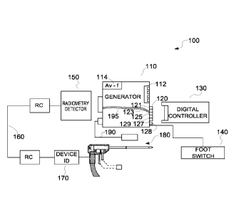
[0030] FIG. 1 is a
block diagram of a surgical system, in accordance with
embodiments of the present disclosure;
[0031] FIG. 2
depicts a resistive identification connector of the surgical system of
FIG. 1, in accordance with an embodiment of the present disclosure; and
[0032] FIG. 3
depicts a plurality of dip switches configured to allow for high
temperature cutoff selectability, in accordance with an embodiment of the
present
disclosure.
[0033] The figures
depict illustrative embodiments of the present disclosure and
are not intended to be exhaustive. One skilled in the art will readily
recognize from the
following detailed description that alternative embodiments of the structures
and methods
illustrated herein may be employed without departing from the principles of
the present
disclosure.
DETAILED DESCRIPTION
[0034] The present
disclosure is generally directed to adding digital outputs to a
microwave generator that is configured to communicate with a digital
controller (or
external adapter or dongle), the digital controller configured to adjust one
or more
operations of the microwave generator in order to manipulate/control a
microwave
applicator connected to the microwave generator.
[0035] One
embodiment of the present disclosure is generally directed to
providing a microwave generator with resistive identification circuitry
configured to
9
CA 02957908 2017-02-10
WO 2016/032666
PCT/US2015/042446
operably communicate with the digital controller. When a microwave applicator
is
connected to the microwave generator, a device ID of the microwave applicator
sends or
transmits or communicates resistive information associated with the microwave
applicator to the resistive identification circuitry, which matches the
resistive information
with resistive channels to identify the type of microwave applicator attached
to the
microwave generator. The digital controller is then enabled to be connected to
the
microwave generator in order to adjust one or more operations of the microwave
generator in order to control the microwave applicator connected to the
microwave
Generator.
[0036] Embodiments
of the microwave ablation systems and components are
described with reference to the accompanying drawings. Like reference numerals
may
refer to similar or identical elements throughout the description of the
figures. As shown
in the drawings and as used in this description, the term "proximal" refers to
that portion
of the apparatus, or component of the apparatus, closer to the user and the
term "distal"
refers to that portion of the apparatus, or component thereof, farther from
the user.
[0037] FIG. 1 is a
block diagram of a surgical system, in accordance with
embodiments of the present disclosure. As shown in FIG. 1, the surgical system
100
includes a microwave generator 110. The microwave generator 110 includes a
resistive
identification connector 120 having a plurality of resistive channels 121,
123, 125, 127,
129, each resistive channel having a plurality of resistive values (see FIG.
2).
[0038] The
microwave generator 110 is configured to be connected to a
microwave applicator 180. The connection between the microwave generator 110
and
the microwave applicator 180 is enabled through a reusable cable 160. In one
exemplary
CA 02957908 2017-02-10
WO 2016/032666
PCT/US2015/042446
embodiment, a radiometry detector 150 is positioned between the reusable cable
160 and
the microwave generator 110. Moreover, the microwave applicator 180 is
associated
with a device ID 170 (or device identifier 170). The device ID 170 may be
incorporated
within the microwave applicator 180 or may be a separate component formed, for
example, in a connector configured to mate with a connector of the reusable
cable 160.
Therefore, the reusable cable 160 connects to the device ID 170, which in turn
is
connected to the microwave applicator 180. Similar device ID components may be
included in the reusable cable 160 and the radiometry detector 150. The
microwave
generator 110 may also be connected to a footswitch 140, which may also
include a
device ID.
[00391 During the
use of the surgical system 100, surgical equipment used when
performing surgery and the control of a variety of different subsystems, may
be required.
Typically, the operation of the subsystems is controlled by a microprocessor-
driven
console (e.g., the microwave generator 110). The microprocessor receives
mechanical
inputs from either the operator of the surgical system 100 or from an
assistant. A control
input device, such as the footswitch 140, is often used to accept mechanical
inputs.
These mechanical inputs originate from the movement of the foot of an operator
to
govern the operation of a subsystem within the surgical system 100. The
mechanical
inputs from the movement of the foot of the operator are translated into
electrical signals
which are fed to the microprocessor controls. The electrical signals are then
used to
control the operational characteristics of a subsystem in the surgical system
100.
[0040] As shown in
Fig. 1, the microwave generator 110 is connected to a remote
temperature probe 190. The remote temperature probe 190 may be a temperature
sensor
11
CA 02957908 2017-02-10
WO 2016/032666
PCT/US2015/042446
such as a thermocouple or a thermistor, and may include a device ID as well.
The
temperature probe 190 is operable to measure a temperature of tissue at a
surgical site. In
one embodiment, the temperature probe 190 may be configured to continuously
output
the temperature signal to the microwave generator 110 allowing a user to
observe the
temperature or to control the microwave generator 110.
[0041] In one
embodiment, the dip switches 112, described in greater detail
below, enable the setting of a cut-off temperature, and when that temperature
is sensed by
the remote temperature probe 190, the microwave generator 110 is shut off. As
to the
monitoring of the temperature, the microwave generator 110 may include a video
screen
(not shown) that displays the temperature signal output from the temperature
probe 190.
The display of the temperature signal may be visual (such as a graph or a
plurality of
colored LEDs), numerical, or otherwise. In other versions, the video screen
may be
mounted to the microwave applicator 180. Still further, the sensed temperature
from the
remote temperature probe 190 may be converted to a digital signal and
transmitted to
digital controller 130, as will be described in greater detail below. The
conversion to a
digital signal may occur in the microwave generator 110 or in the digital
controller 130
without departing from the scope of the present disclosure.
[0042] As noted
above, the microwave generator 110 is further configured to
connect and communicate with a digital controller 130. The digital controller
130 may
also be referred to as an external adapter or a dongle. The digital controller
130 is
configured to be connected to the resistive identification connector 120 of
the microwave
generator 110, and one or more analog or digital connectors 128. The resistive
identification connector 120 includes a plurality of resistive channels 121.
123, 125, 127,
12
CA 02957908 2017-02-10
WO 2016/032666
PCT/US2015/042446
129. The device identifier 170 of the microwave applicator 180 includes
identification
information that is associated with one of the resistive channels (e.g., 121)
of the plurality
of resistive channels 121, 123, 125, 127, 129 of the resistive identification
connector 120
to enable the digital controller 130 to receive information regarding the
microwave
applicator 180, and other components connected to the system 100. This
information
received via the resistive identification connector 120 enables the controller
130 to
execute algorithms to control the microwave generator 110 and the microwave
applicator
180.
[0043] As shown in
FIG. 2, the resistive identification connector 120 has a
plurality of resistive channels 121, 123, 125, 127, 129, each resistive
channel capable of
relaying a plurality of resistive values, each of which may relate to a
different aspect of
the surgical system 100. As an example, the device ID 170 of the microwave
applicator
170 transmits or sends or communicates information to the resistive
identification
connector 120. This information includes at least resistance or resistive
values associated
with the microwave applicator 180, which can be used to inform the controller
130 of the
attributes of the microwave applicator 180, its functional characteristics,
how energy is to
be applied through the microwave applicator 180, and other features.
[0044] The
resistive value information is matched with one of the resistive
channels 121, 123, 125, 127, 129 of the resistive identification connector
120. For
example, the resistive value information of the microwave applicator 180
connected to
the microwave generator 110 may correspond to resistive values of the second
resistive
channel, i.e., channel 123. Once a match of resistances has successfully
occurred, the
digital controller 130 is capable of determining the type of microwave
applicator 180.
13
CA 02957908 2017-02-10
WO 2016/032666
PCT/US2015/042446
For example, the microwave applicator 180 may be a single mode applicator, a
multi-
mode applicator, a needle applicator, a helical applicator, a coil applicator,
or some other
type of applicator. Once the digital controller 130 identifies the type of
microwave
applicator attached to the microwave generator 110, the digital controller 130
can control
at least one operation of the microwave generator 110.
[0045] One or more
operations or functions of the microwave generator 110 may
be altered or changed or adjusted or manipulated by the digital controller
130. The
resistive identification connector 120 of the microwave generator 110 can
identify the
type of surgical instrument or microwave applicator attached to the microwave
generator
110. Thus, identification of the type of microwave applicator occurs by
resistance
matching of characteristics of the microwave applicator, and other components
of the
system 100 to the resistance channels 121, 123, 125, 127, 129 of the resistive
identification connector 120. In one exemplary embodiment, five resistance or
resistive
channels may be provided by the resistive identification connector 120.
However, one
skilled in the art may contemplate using any number of resistive channels. The
details of
the resistive channels are described below in detail with respect to FIG. 2.
[0046] In the
exemplary embodiment of FIG. 2, the resistive identification
connector 120 includes five channels 121, 123, 125, 127, 129. Each channel
includes a
plurality of resistive values 201, 203, 205, 207, 209. The resistive value 201
may be a
range of resistance values designated as RIA, RIB, R1c, and RID. This range of
resistive
value 201 may be within, e.g., 0-50 ohms. The resistive value 203 may be a
range of
resistance values designated as R2A, R2B, R,c, and R/D. This range of
resistive value 203
may be within, e.g., 0-10 ohms. The resistive value 205 may be a range of
resistance
14
CA 02957908 2017-02-10
WO 2016/032666
PCT/US2015/042446
values designated as R3A, R3B, R3c, and R3D. This range of resistive value 205
may be
within, e.g., 10-100 ohms. The resistive value 207 may be a range of
resistance values
designated as R4A, R4B, R4C, and R4D. This range of resistive value 207 may be
within,
e.g., 100-1000 ohms. The resistive value 209 may be a range of resistance
values
designated as RSA, R5B, R5c, and R5D. This range of resistive value 209 may be
within,
e.g., 1000-10,000 ohms. Each resistive channel 121, 123, 125, 127, 129 is
dedicated to a
different type of surgical instrument. As a result, depending on which
resistive band is
active, the digital controller 130 identifies the specific surgical instrument
and determines
(as well as adjusts) limits or functions of one or more parameters of the
surgical
instrument. In addition, because of the range of resistive values in each
channel, multiple
parameters may be set by a single set of resistance values. Thus, if a value
is detected at
RIA this may indicate a power setting, and a value at R?A may indicate a
maximum time
application setting. A value at R3A may indicate a maximum power setting, etc.
Because
of the broad ranges of resistive values available, a wide arrange of settings,
and variables,
as well as information about the microwave applicator 180, the other
components of
system 100, and the expected functionality of the microwave generator can be
conveyed
to the controller 130.
[0047] The use of
this resistive ID scheme has a further effect in that it allows for
the controller 130, which is removable from the microwave generator 110, to be
switched
to accommodate different types of or new generations of microwave applicators
180,
remote temperature probes 190, and other components without having to take the
microwave generator 110 out of service to perform software, firmware, or
hardware
upgrades.
CA 02957908 2017-02-10
WO 2016/032666
PCT/US2015/042446
[0048] The
controller 130 may also be able to ascertain and retain information
about all of the devices which are connected to the microwave generator 110.
In this
manner usage times of devices, such as the reusable cable 160, may be
collected as
monitored. Further, antiquated ablation probes 180 may be prevented from use,
or even
individual ablation probes 180 whose resistive ID information is already
stored in an on-
board memory on the controller 130 may be prevented from being re-used.
[0049] For example
the reusable cable 160 and the microwave applicator 180
may both be disposable. The reusable cable 160 and the microwave applicator
180 may
be used only once or may be used a predetermined number of times. A counter in
the
digital controller 130 may be associated with either the reusable cable 160 or
the
microwave applicator 180 or both. The counter may count the number of times
the
reusable cable 160 and/or the microwave applicator 180 having a specific
resistive ID
configuration has been used. After a predetermined number of uses, the counter
may
trigger an indicator (e.g., a visual or audible indicator) to prompt a user to
replace the
reusable cable and/or the microwave applicator. This and other data pertaining
the use of
the surgical system 100 and the components connected thereto may be stored
locally in a
memory in the digital controller, and may be downloaded to an external memory
for later
evaluation and analysis without departing from the scope of the present
disclosure.
[0050] Moreover,
three or more separate resistive values could be used in the
device ID 170. The digital controller 130 would read all the values via the
pass through
and match them to a matrix identification to determine a device type and a
manufacturer
date. This increases the number of device IDs which could be used, and could
also
enable device use monitoring. If, for example, three readable elements were
used in the
16
CA 02957908 2017-02-10
WO 2016/032666
PCT/US2015/042446
device ID 170, each having 20 resistive value options (20x20x20 values ¨ 8000
unique
combinations), as disposables are tracked in lots, this could allow for the
digital
controller 130 to limit the use of the expired lots.
[0051] Therefore,
referring back to FIG. 1, once a connection has been
established between the microwave applicator 180 and the microwave generator
110, the
resistive identification connector 120 of the microwave generator 110
communicates
directly with the device ID 170 of the microwave applicator 180 to identify
the type of
microwave applicator 180 connected to the microwave generator 110. This is
accomplished by communicating resistance values incorporated in the device ID
170 and
associated with the microwave applicator 180 directly to the resistive
identification
connector 120. For example, the device ID 170 may communicate various
resistive
values associated with the microwave applicator 180 that fall into the 10-100
ohm range.
The resistive identification connector 120 corresponds such values with the
second
channel, e.g., channel 123 of the resistive identification connector 120. The
second
channel 123 of the resistive identification connector 120 corresponds to,
e.g., a multi-
mode microwave ablation applicator. Therefore, the resistive identification
connector
120 conveys this information to the controller 130, which identifies the
microwave
applicator 180 as a multi-mode microwave ablation applicator.
[0052]
Subsequently, once the match has occurred between the resistive values
provided by the device ID 170 of the microwave applicator 180, the digital
controller 130
is able to control the multi-mode microwave ablation applicator by adjusting
one or more
operations of the microwave generator 110. Thus, once the device ID 170
registers the
17
CA 02957908 2017-02-10
WO 2016/032666
PCT/US2015/042446
microwave applicator 180 with the digital controller 130, the digital
controller 130 is able
to adjust functionality of the microwave generator 110 and the microwave
applicator 180.
[0053] Therefore,
the microwave generator 110 (which may be an existing off-
the-shelf generator) can be provided with additional functionality, without
the need of
replacing the generator within the surgical system 100. The digital controller
130 acts as
a smart peripheral device for enhancing the operations or functions provided
by the
existing microwave generator 110.
[0054] Another
aspect of the present disclosure is the use of the radiometer 150.
The radiometer 150 detects emissions from materials such as tissue, for
example. The
emissions detected by the radiometer 150 both before and after application of
microwave
energy can be sampled and converted to either an analog voltage or a digital
signal and
forwarded to the digital controller 130.
[0055] With this
information, the digital controller 130 may change or alter or
modify or adjust the energy delivered by the microwave generator 110 based on
the tissue
characteristics encountered by the microwave applicator 180. For example, when
the
tissue contacted by the microwave applicator 180 and sensed by the radiometer
150 is
healthy tissue, the digital controller may prevent the microwave generator 110
from
applying energy to the tissue. On the other hand, as the microwave applicator
180
approaches tumorous tissue, the digital controller 130 may prompt the
microwave
generator 110 to transmit energy to cauterize the tumorous tissue. The
detection of the
tumorous tissue (or healthy tissue) may be enabled by first transmitting from
the
microwave generator 110 through the microwave applicator 180 a non-therapeutic
signal
(e.g., very low power or duration) at the tissue in question and evaluating
the emitted
18
CA 02957908 2017-02-10
WO 2016/032666
PCT/US2015/042446
response to the interrogation. The digital controller can then employ
algorithms and
protocols to ascertain the type of tissue and present these results to the
user via a
connected display or an output on the microwave generator, or on the digital
controller
130 itself.
[0056] Further, by
continuing to detect the change in the radiometry reading
during the application of energy, the digital controller 130 can make
determinations
regarding the cessation, or the sufficiency of the treatment of the tumorous
tissue. The
signals generated by the radiometer 150 permit the digital controller 130 to
adjust
operations of the microwave generator 110 based on the feedback received from
the
microwave applicator 180. The radiometry detector 150 enables radiometric
detection of
heating of the tissue by detecting electromagnetic waves of a frequency and
signal
strength emitted by the tissue indicating tissue temperature. Preferably the
radiometry
detector 150 operates at a frequency in the microwave range. The radiometry
detector
150 is an optional component of the surgical system 100.
[0057] The
radiometer 150 is in electrical communication with a voltage to
frequency converter 114 (see FIG. 1). The voltage to frequency converter 114
may
enable the digital controller 130 to receive either an analog voltage or a
digital
representative of the emissions received by the radiometer 150. Digital
representation of
the radiometer output has advances common to digital signal communications,
including
but not limited to enhanced bandwidth and noise immunity.
[0058] With
combined use of the digital controller 130 and radiometer
measurement of the tissue state about the ablation probe, the system could
dynamically
avoid certain unwanted physiological responses which occur during rapid
heating, such
19
CA 02957908 2017-02-10
WO 2016/032666
PCT/US2015/042446
as the rapid phase change of physiological fluids from liquid to gas. The
controller 130
would in this case avoid exceeding 100dC as measured by the radiometer by
pulsing/reducing microwave power to the probe. Other dynamic control of the
ablation
progression is envisioned and not limited to this example.
[0059] According
to a further embodiment of the present disclosure, information
communicated by the device ID 170 of the microwave applicator 180 may be
directly
sent to the digital controller 130 via a digital pass-through line 195 to
allow direct
communication between the microwave applicator 180 (or other components of the
system 100) and the digital controller 130. The at least one digital pass-
through line 195
includes electrical isolation. Therefore, even in instances where the
microwave generator
110 does not use any programmable logic and there is no computer processing
conducted
within the microwave generator 110, the use of the digital pass-through line
195 allows
for all digital communications between the microwave applicator 180 (or other
components of the system 100) and the digital controller 130.
[0060] FIG. 3
depicts a plurality of dip switches configured to allow for high
temperature cutoff selectability, in accordance with an embodiment of the
present
disclosure.
[0061] The dip
switch configuration 400 depicts five dip switch configurations
for three dip switches, each associated with a different temperature (or
temperature
range). Of course, one skilled in the art may contemplate a different number
of dip
switches each associated with a different temperature or temperature range.
For example,
in this exemplary embodiment, the first dip switch configuration 410 may
represent a
shut-off temperature of 40 degrees, the second dip switch configuration 420
may
CA 02957908 2017-02-10
WO 2016/032666
PCT/US2015/042446
represent a shut-off temperature of 45 degrees, the third dip switch
configuration 430
may represent a shut-off temperature of 50 degrees, the fourth dip switch
configuration
440 may represent a shut-off temperature of 55 degrees, and the fifth dip
switch
configuration 450 may represent a shut-off temperature of 60 degrees. The
temperature
shut-off for each dip switch configuration 410, 420, 430, 440, 450 may be
represented in
binary form, as illustrated in FIG. 3. Therefore, a user is permitted to
manually select a
shut-off temperature related to the microwave applicator 180 (see FIG. 1) to
be sensed by
the remote temperature probe 190. When the selected dip switch configuration
temperature is sensed by the remote temperature probe, the microwave generator
110 can
be automatically shut-off and prevented from providing additional energy to
the
microwave applicator 180 based on a tissue temperature measured at the
surgical site.
This may be performed via analog circuitry within the microwave generator 110,
or by
sending a signal to the digital controller 130 which itself generates a
control signal
shutting off the generator.
[00621 The
features and aspects of the present disclosure may be implemented in
surgical system 100 in any suitable fashion, e.g., via the hardware and
software
configuration of surgical system 100 or using any other suitable software,
firmware,
and/or hardware.
[0063] For
instance, when implemented via executable instructions, various
elements of the present disclosure are in essence the code defining the
operations of such
various elements. The executable instructions or code may be obtained from a
readable
medium (e.g., a hard drive media, optical media, EPROM, EEPROM, tape media,
cartridge media, flash memory, ROM, memory stick, and/or the like) or
communicated
21
CA 02957908 2017-02-10
WO 2016/032666
PCT/US2015/042446
via a data signal from a communication medium (e.g., the Internet). In fact,
readable
media may include any medium that may store or transfer information.
[0064] The
computer means or computing means or processing means may be
operatively associated with the assembly, and is directed by software to
compare the first
output signal with a first control image and the second output signal with a
second
control image. The software further directs the computer to produce diagnostic
output.
Further, a means for transmitting the diagnostic output to an operator of the
verification
device is included. Thus, many applications of the present disclosure could be
formulated. The exemplary network disclosed herein may include any system for
exchanging data or transacting business, such as the Internet, an intranet, an
extranet,
WAN (wide area network), LAN (local area network), satellite communications,
and/or
the like. It is noted that the network may be implemented as other types of
networks.
[0065]
Additionally, "code" as used herein, or "program" as used herein, may be
any plurality of binary values or any executable, interpreted or compiled code
which may
be used by a computer or execution device to perform a task. This code or
program may
be written in any one of several known computer languages. A "computer," as
used
herein, may mean any device which stores, processes, routes, manipulates, or
performs
like operation on data. A "computer" may be incorporated within one or more
transponder recognition and collection systems or servers to operate one or
more
processors to run the transponder recognition algorithms. Moreover, computer-
executable instructions include, for example, instructions and data which
cause a general
purpose computer, special purpose computer, or special purpose processing
device to
perform a certain function or group of functions. Computer-executable
instructions also
22
CA 02957908 2017-02-10
WO 2016/032666
PCT/US2015/042446
include program modules that may be executed by computers in stand-alone or
network
environments. Generally,
program modules include routines, programs, objects,
components, and data structures, etc. that perform particular tasks or
implement particular
abstract data types.
[0066] Though the
digital controller 130 is generally described herein as
automatically controlling or adjusting or operating one or more functions of
the
microwave generator 110, it is understood that that a user may also manually
adjust one
or more operations of the microwave generator 110.
[0067] Concerning
the exemplary embodiments of the present disclosure, the
microwave applicator may be a rigid applicator or a flexible applicator. One
skilled in
the art may contemplate using any type of applicator.
[0068] This
description may use the phrases "in an embodiment," "in
embodiments," "in some embodiments," or "in other embodiments," which may each
refer to one or more of the same or different embodiments in accordance with
the present
disclosure.
[0069]
Electromagnetic energy is generally classified by increasing energy or
decreasing wavelength into radio waves, microwaves, infrared, visible light,
ultraviolet,
X-rays and gamma-rays. As it is used in this description, "microwave"
generally refers
to electromagnetic waves in the frequency range of 300 megahertz (MHz) (3x10⁸
cycles/second) to 300 gigahertz (GHz) (3x10¹¹ cycles/second). As it is used in
this
description, "ablation procedure" generally refers to any ablation procedure,
such as, for
example, microwave ablation, radiofrequency (RF) ablation, or microwave or RF
ablation-assisted resection.
23
CA 02957908 2017-02-10
WO 2016/032666
PCT/US2015/042446
[0070] As it is
used in this description, "energy applicator" generally refers to any
device that can be used to transfer energy from a power generating source,
such as a
microwave or RF electrosurgical generator, to tissue. For the purposes of the
present
disclosure, the term "energy applicator" is interchangeable with the term
"energy-
delivery device." As it is used in this description, "transmission line"
generally refers to
any transmission medium that can be used for the propagation of signals from
one point
to another.
[0071] As it is
used in this description, the term "controller" refers to any
electrical device that employs digital and/or analog components to generate
digital and/or
analog signals to control or drive another device. The term "controller" may
refer to a
digital signal processor, a microcontroller, or a computer having a processor,
a memory,
and input/output ports for carrying out some of the methods described herein.
[0072] The word
"exemplary" is used herein to mean "serving as an example,
instance, or illustration." Any embodiment described herein as "exemplary" is
not
necessarily to be construed as preferred or advantageous over other
embodiments. The
word "example" may be used interchangeably with the term "exemplary."
[0073] Persons
skilled in the art will understand that the devices and methods
specifically described herein and illustrated in the accompanying drawings are
non-
limiting exemplary embodiments. The features illustrated or described in
connection
with one exemplary embodiment may be combined with the features of other
embodiments. Such modifications and variations are intended to be included
within the
scope of the present disclosure.
24
CA 02957908 2017-02-10
WO 2016/032666
PCT/US2015/042446
[0074] The
foregoing examples illustrate various aspects of the present disclosure
and practice of the methods of the present disclosure. The examples are not
intended to
provide an exhaustive description of the many different embodiments of the
present
disclosure. Thus, although the foregoing present disclosure has been described
in some
detail by way of illustration and example for purposes of clarity and
understanding, those
of ordinary skill in the art will realize readily that many changes and
modifications may
be made thereto without departing form the spirit or scope of the present
disclosure.
[0075] While
several embodiments of the disclosure have been shown in the
drawings, it is not intended that the disclosure be limited thereto. as it is
intended that the
disclosure be as broad in scope as the art will allow and that the
specification be read
likewise. Any combination of the above embodiments is also envisioned and is
within
the scope of the appended claims. Therefore, the above description should not
be
construed as limiting, but merely as exemplifications of particular
embodiments. Those
skilled in the art will envision other modifications within the scope and
spirit of the
claims appended hereto.