Note: Descriptions are shown in the official language in which they were submitted.
CA 02958176 2017-02-14
WO 2015/031191
PCT/US2014/052279
ARTICLE DISPENSER AND METHODS RELATING TO SAME
Cross Reference to Related Applications
[0001] This application claims the benefit of Application No. 61/945,668,
filed on February 27,
2014, and titled Bag, Dispenser, and Related Articles, and also claims the
benefit of Application No.
61/959,566, filed on August 24, 2013, and titled Bag and Dispenser, and which
are both hereby
incorporated by reference in their entireties.
BACKGROUND
1. Field of the Invention:
[0002] The present invention generally relates to plastic film articles
such as plastic bags and
sheets and their dispensers and systems. More specifically they relate to a
unique bag, sheet, and
tissue, and their disposable dispenser cartons and permanent dispensers, for
example metal,
aluminum, and plastic, and their related systems, suitable for use in retail,
supermarket,
industrial/commercial, restaurant, and other related applications.
2. Background Art:
[0003] Plastic bags are commonly used in retail applications to carry food and
merchandise,
and commonly used in self-serve applications such as bakery departments.
Plastic bags dispensed
from traditional dispenser cartons are typically extracted out of a die-cut
portion on the carton's
top surface adjacent the front panel. It is commonly known that plastic
merchandise bags
dispensed from cartons as such tend to stick together when dispensed, thus
multiple dispensing of
bags is common. This problem is exemplified in U.S. Patent No. 5,509,570 (the
'570 patent) to
DeMatteis (a co-inventor of this application), which quantifies the
substantial waste associated
with plastic bag dispensing from traditional dispenser cartons. When bags are
double-, triple- or
multiply-dispensed, it is not uncommon for those bags to be pushed behind the
dispenser carton
in the store's check-out counter, and subsequently thrown out in the trash,
usually by janitorial
workers who are doing their job. The bag described in the '570 patent at least
provides an
improvement over traditional prior art dispenser cartons.
[0004] Very little has changed in the last twenty years other than bag
manufacturing
companies providing dispensing systems comprised of metal racks, hangers, and
plastic bag
hooks. Examples of these systems are illustrated in U.S. Patent No. 5,013,290
and U.S. Patent
No. 6,715,260 (the '260 patent), both to DeMatteis. These systems are
generally acceptable in
many applications, as is commonly seen in supermarket front end applications,
and require space
1
CA 02958176 2017-02-14
WO 2015/031191
PCT/US2014/052279
atop counters and other working surfaces, such as a vertical wall. They are
considered somewhat
of a nuisance to be located atop a working surface and are generally
unattractive. At times,
separate metal holders and dispensers are used for multiple bag sizes, thus
magnifying these
issues. Without question, retailers prefer not to have bag dispensers mounted
atop working
counter tops, or alongside the counters on a vertical surface, and would
prefer a carton dispenser
hidden out of view under a counter. Likewise, for self-serve applications, for
example in self-
serve bakeries, it is preferred to have dispenser cartons that fit into the
bag compartments located
under the pastry cabinets instead of mounting them on some form of external
hook or rack. In this
particular instance, the appearance of the bakery area is important to
retailers, and mounting
external holders takes away from an otherwise attractive, clean, professional
appearance.
[0005] Dispensing bags from traditional prior art dispenser cartons typically
take about 10-13
seconds to extract a bag, find the bag mouth opening, grasp the two opposing
handles, open the
bag, and set it upright on a counter top, ready for loading. This is assuming
that multiple bags are
not accidentally dispensed and that the two opposing bag walls don't stick
together, which foils
the ability to grasp the two opposing bag walls and open it up, further
increasing the time
required to dispense and prepare a bag for loading. This exemplifies why bags
dispensed from
hooks and racks are more prevalent in higher volume retailers. It is commonly
understood that the
relatively long time frame to prepare a bag for loading when dispensed from
traditional prior art
cartons is unacceptable in retail stores, supermarkets, restaurants, and so
on. Such a long time
frame to dispense a bag, and prepare it for loading, adds up over the course
of a year to a rather
enormous labor expense for larger retailers.
[0006] The use of certain prior art products such as Dual-tab bags can
significantly improve
dispensing as they tend to avoid multiple-dispensing, and the bags also open
up when dispensed.
This is illustrated in U.S. Patent Nos. 4,759,639 to DeMatteis and 5,497,884
(the '884 patent) to
DeMatteis et al. While these bag styles improve dispensing and productivity
and reduce waste,
they cost more to manufacture and package into their dispenser cartons.
[0007] Another merited bag dispensing system is one that dispenses from a hook
and leaves no
residue (bag tab) behind. This is illustrated in patent U.S. Patent No.
5,881,882 (the '882 patent)
to Fletcher et al. However, carry bags with or without die-cut handles¨not T-
shirt bags¨in this
configuration tear a portion of the bag top as illustrated in FIGS. 9-12 of
the '882 patent. This
causes two new problems, one being a weakening of the bag top where a die-cut
handle is
located, and two, it creates an unattractive appearance. The bags disclosed in
the '260 patent on
the other hand leave no tears in the bag construction and have an attractive
wave-top appearance.
2
CA 02958176 2017-02-14
WO 2015/031191
PCT/US2014/052279
All of these bag dispensing systems have merit for dispensing bags one-at-a-
time and speeding up
productivity, but all require some form of external hook or rack, with the
exception of the bag
system disclosed in the '884 patent, which has the added cost of a retaining
hook system affixed
within the carton.
[0008] Other one-at-a-time dispensing systems for plastic bags include a
multitude of roll bag
configurations, most of which use a détente as a retainer to separate a bag
being dispensed from
the next bag on the roll. An example of such a roll bag and dispenser is
illustrated in U.S. Patent
No. 6,234,431 (the '431 patent) to Simhaee. Other roll bags are illustrated in
U.S. Patent No.
5,209,371 (the '371 patent) to Daniels and U.S. Patent No. 5,170,957 (the '957
patent) to
Carpenter. While roll bags offer certain efficiencies in manufacturing, they
are rarely a
consideration for larger, thicker carry bags, and those that require better
quality print copy such
as those used in department stores and restaurant take out bags. Roll bag
manufacturing
operations are well-known for their generally inferior print ability. Roll
bags also tend to be
impractical for use in high volume outlets where productivity is important
when dispensing,
opening, readying, and loading bags, which is time consuming. Much like the
traditional
dispenser carton, they take 10-13 seconds to complete the dispensing operation
and prepare for
loading.
[0009] Perhaps the biggest detriment of all external racks and hook dispensing
systems, as
described for example in the '431, '371, '260 and '882 patents, is the
substantial cost to purchase
and install the hardware. It also requires reasonably experienced employees to
properly install the
racks and hooks. The initial cost is usually born by the bag manufacturer, but
accounted for in its
sales price (and usually with a long-term supply contract). Also, racks and
hooks tend to break
and require replacement, which replacement costs are subsequently born by the
retailer.
[00010] In addition to bags being dispensed one-at-a-time, the same benefit
holds true for a
myriad of tissue sizes and types used in bakery and other sheet uses such as a
meat department or
deli. Other sheet type applications include tint strips used in the salon
trade. Hair stylists use them
when applying coloring to a customer's hair. The tint strip is laid atop a
lock of hair that has been
treated with a tint chemical, which is then folded up in the tint strip. The
tint strip prevents the
tint chemical from inadvertently touching, and thus tinting adjacent sections
and locks of hair.
Traditional tissue and sheet dispensing systems are generally like that
described in U.S. Patent
No. 3,269,593 (the '593 patent) to Lodewick.
[00011] The equipment that manufactures interfolded tissue as described in the
'593 patent is
generally expensive with fixed sizes. It is conceivable this technology could
be used in the bag
3
CA 02958176 2017-02-14
WO 2015/031191
PCT/US2014/052279
industry but would be extremely costly. Likewise, changing from tissue to bag
manufacturing
would be impractical and would most likely require new machinery altogether.
There would be
little flexibility with sizing in these types of interleaved manufacturing
systems.
[00012] Plastic bags, tissues, and sheets that are attractive and useful, and
can be dispensed
from a carton without an additional cost for new bag machines (interleaving or
otherwise),
machine conversion, hardware installation, added carton expense, and so on,
and overcome the
numerous problems associated with prior art dispensers would be valuable to
these trades and
many others.
SUMMARY
[00013] The disposable and permanent dispensers, plus the plastic bags and
articles of the present
invention, overcome the problems associated with prior art. The dispensers of
the present invention
dispense articles such as bags, sheets, or tissues one-at-a-time by utilizing
interconnected bag packs or
article packs, a unique combination of a separator, a retainer, and elevator,
and at times a restraining
dispenser cut-out. The separator serves unlike a détente in that it does not
resist separation of film
articles such as bags on a roll, like those illustrated in the '431, '371 and
'957 patents. Instead, the
separator of the present invention allows the film plies of a first bag or
tissue article to slide over it, as
the first article pulls a top wall of a second interconnected article up and
over the separator through a
weak bond between their outer film surfaces. The weak bond then releases as
the top wall of the
second article falls back down atop the separator, thus it is immediately
ready to be grasped and
dispensed. Upon executing the dispensing operation, a dispensed bag article
automatically opens
wide, and can be quickly set atop a counter, ready for loading in a matter of
a few seconds. A
dispensed tissue is firmly grasped in the user's hand, or as revealed herein
it may be effectively
hooked through an aperture. These dispensing operations are impossible with
the '431, '371 and '957
bags, or any other common plastic bag dispensed from a carton or permanent
fixture, with the
exception of the '884 bag. However, as required with the '884 bag, the present
invention does not
require the added hardware inserted in the carton, nor the added labor to load
the stacked bags during
the manufacturing operation. The elimination of the internal hardware that
secures bag packs to the
dispenser improves environmental properties and reduces cost by 3%-5% or more.
The tissue/sheet
dispensing operation of the present invention would also be impossible with
any traditional type of
interfolded or cut sheets, regardless of material.
[00014] Furthermore, where the prior art bags on rolls and common merchandise
bags using
traditional dispenser cartons require 10-13 seconds to completely dispense,
open and prepare for
loading, the bag of the present invention is ready for loading in about 3-4
seconds. Considering that
4
CA 02958176 2017-02-14
WO 2015/031191
PCT/US2014/052279
labor rates in the United States would be effectively calculated at $20 per
hour (includes tax liabilities,
expenses, insurance, etc.), that computes to about 1/2 cent per second. Thus,
there is an added labor
cost of $.035 - $.045 per prior art bag when dispensed and loaded by an
employee. For a large retailer
or industrial bag user who dispenses 10 million food or retail bags a year,
the extra labor cost equates
to about $350,000 to $450,000 annually. Likewise, prior art tissue and sheets
tend to dispense
efficaciously, however, larger sheets and items like tint strips or deli
sheets that are stacked in boxes
and cartons, tend to be cumbersome and can take from 5-8 seconds to prepare
for use, whereas the
present invention takes about 1-2 seconds to grasp and put into use. It will
be clearly demonstrated
that the use of the bag and sheet articles of the present invention save
substantial time and labor.
[00015] The present invention also incorporates the use of a novel retainer
that is inserted inside the
dispenser, atop a stack of articles, which helps retain the bag or sheet
article stacks in place during the
dispensing operation. This is generally not required with heavier bags and
sheets. However, with
thin-gauged articles, this simple means of maintaining the stack in a layflat
disposition in the
dispenser, eliminates the dispensing of multiple articles and instead
contributes to the preferred
withdrawal of one article at a time. With lightweight film articles, the
present invention may also
make use of an elevator, which is inserted inside the dispenser prior to
stacking the articles inside. As
its name indicates, the elevator is a simple, novel way, to cause the stack of
articles to rise up during
dispensing, all the while maintaining the enclosed bag stack in a layflat
disposition. Furthermore, with
or without the use of an elevator, retainer, or even a separator, the
invention may employ solely a
restraining dispenser cut-out (or opening on a permanent dispenser) with a
series of interconnected
articles packed inside to effect the one-at-a time dispensing operation. This
type of configuration may
typically be used for more lightweight articles, and requires the right
balance of a cut-out/opening that
sufficiently restrains; and articles with interconnections whose bonds will
effectively break when they
are withdrawn through the restricting cut-out/opening.
[00016] The dispensing operation of the present invention bags is also
natural, instinctive to users,
as they dispense articles much like they would a traditional bag from a box.
The two primary
differences being that a first dispensed bag opens wide in the user's hand
when dispensed, and the
front wall of the second bag in sequence is always ready to be subsequently
grasped and instantly
dispensed. Dispensing sheet articles is essentially the same, with a first
dispensed tissue automatically
prepares a second tissue to be subsequently grasped and instantly dispensed.
Whether bag, tissue,
sheet or otherwise, the dispensing operation of the present invention is
intuitive, that is, little to no
training is required.
5
CA 02958176 2017-02-14
WO 2015/031191
PCT/US2014/052279
[00017] The present invention used with disposable cartons incurs no
additional cost for hardware,
racks, hooks, and so on and requires no installation by skilled or unskilled
workers. The dispenser
carton may be manufactured by most traditional carton suppliers and might cost
marginally more than
traditional RSC cartons, if anything at all. The carton of the present
invention is easy for employees to
know how to open and use, as it incorporates a traditional perforated opening,
but in a special
configuration that delineates the unique separator or dispensing qualities of
the present invention.
Anyone who has opened any form of traditional dispenser carton, or box of
facial tissues, will
instinctively know how to open the carton of the present invention.
[00018] The present invention used with fixed, permanent dispensers incurs
only an initial cost of
the dispenser, and may be installed by skilled or unskilled workers. The
permanent dispenser may be
manufactured by most traditional wire and sheet metal products suppliers and
would typically cost no
more than traditional plastic bag racks. The permanent dispenser of the
present invention is easy for
employees to know how to use, as it is intuitive for an employee to insert one
or more large cartridges
of bags. The permanent dispenser incorporates an opening much like that used
in the disposable
carton, but its construction is typically made of metal, although not limited
thereto, and delineates the
unique separator and dispensing qualities of the present invention. Anyone who
has dispensed a facial
tissue from a box will instinctively know how to dispense article from the
permanent dispenser of the
present invention.
[00019] Furthermore manufacturing of the bag articles of the present invention
may be
manufactured on highly advanced, high-speed bag machinery¨or on antiquated bag
machines¨in
either sideweld or bottom-seal operations. They may be essentially any size,
with bottom or side
gussets, printed or imprinted, and only require well-understood, minor
machinery modifications. They
may also include a variety of shapes, handle configurations, and designs that
enhance atUactiveness,
including those along the lines of the Bell BagsTM described in the '570
patent and other bag
configurations described herein. More interesting is that the tissue and sheet
articles of the present
invention can also be manufactured on the same bag equipment with a minor
slitting operation.
[00020] Another important benefit of the bag and dispenser of the present
invention is its effect on
the reduction of waste as its one-at-a-time dispensing is clearly superior to
the prior art bags and the
wastage associated with their respective prior art dispensers. The potential
for multiple dispensing is
much lower (if at all) than all prior art, including the '884 and '570 bags.
It is estimated that 8%-10%
of all retail, self-serve bakery bags, and so on, are double dispensed and
thrown in the trash.
[00021] It is an object of this application to illustrate various preferred
embodiments of the
disposable carton and permanent dispensers, and methods of dispensing of the
present invention, and
6
CA 02958176 2017-02-14
WO 2015/031191
PCT/US2014/052279
its unique bags, tissues, and other film articles, and to broadly state the
methodologies that may be
used in order to manufacture, dispense, and use the dispenser, bags, and other
articles of the present
invention.
BRIEF DESCRIPTION OF THE DRAWINGS
[00022] FIG. 1A is an upper, right hand, perspective view of an exemplary
empty carton in
accordance with the principles of the present invention.
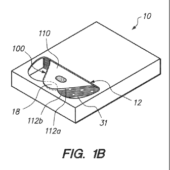
[00023] FIG. 1B is a similar view to FIG. 1 with a stack of exemplary bag
articles packed inside
and a first bag ready for dispensing.
[00024] FIG. 1C is a side cutaway view taken along lines 1C-1C of the carton
and bag articles
in FIG. 1B.
[00025] FIG. 2A is a similar view to FIG. 1B with the dispenser removed
leaving the exemplary
stack of bags.
[00026] FIG. 2B is a similar view to FIG. 2B illustrating the accordion effect
of
interconnections between bags in the bag pack of FIG. 2A.
[00027] FIG. 3A is a similar view to FIG. 1B with the first bag article of the
bag pack being
dispensed from the carton.
[00028] FIG. 3B is a similar view to FIG. 3A illustrating a subsequent stage
of dispensing the
first bag article with the top wall of the second bag in sequence being
readied for a future
dispensing.
[00029] FIG. 3C is a upper, right hand, perspective view of an exemplary
dispensed bag of
FIGS. 3A and 3B, completely dispensed from the carton and set upright ready
for loading.
[00030] FIG. 4A is a plan view (in its layflat configuration) illustrating the
exemplary bag in
FIGS. 1B ¨ 3C, whereas the handle portions are pre-creased, allowing them to
fold out of the
way, making the bag easier to load.
[00031] FIG. 4B is a blown up plan view of the outer handle portions of a
variation of the bag
shown in FIG. 4A.
7
CA 02958176 2017-02-14
WO 2015/031191
PCT/US2014/052279
[00032] FIG. 5A is a similar view to FIG. 1B illustrating another embodiment
of the dispenser
with the front die-cut line in the dispensing opening serving as the separator
in accordance with
the principles of the present invention.
[00033] FIG. 5B is a side cutaway view of the carton and bag packs of FIG. 5A
taken along
lines 5B-5B and showing a ramp to compensate for varying bag thicknesses.
[00034] FIG. 5C is a similar view to FIG. 5A illustrating an exemplary means
to prepare a first
bag in a bag pack for instant dispensing.
[00035] FIG. 6A is a similar view to FIG. 1B illustrating another embodiment
of a carton and
loaded article (bag) stack in accordance with the principles of the present
invention for dispensing
lightweight bag and sheet articles.
[00036] FIG. 6B is a side cutaway view of the carton and bag stack of FIG. 6A
taken along
lines 6B-6B and depicting a retainer to help maintain the bag stack in a
layflat disposition thus
preventing bag articles from bunching up when dispensed.
[00037] FIG. 7 is a similar view to FIG. 6B of an exemplary carton and bag
stack including an
elevator that helps maintain a stack of articles in a layflat disposition thus
preventing bag articles
from bunching up when dispensed.
[00038] FIG. 8A is an upper, right hand, perspective view of an exemplary set
of tissue articles
folded in accordance with the principles of the present invention illustrating
the accordion effect
of their interconnections.
[00039] FIG. 8B is a broken side cutaway view of the dispensing end of the
dispenser carton in
FIG. 7 illustrating the tissue or sheet articles of the present invention in a
ready to dispense
configuration.
[00040] FIG. 9A is an upper, left hand, perspective view of a set of exemplary
tint strip articles
constructed in accordance with the principles of the present invention with
apertures located on
one end, and illustrating the accordion effect of their interconnections.
[00041] FIG. 9B is a similar view to FIG. 8A with the exemplary set of tint
strips loaded in the
carton and illustrating how the tint strip articles with their apertures may
be placed in a ready to
dispense configuration.
8
CA 02958176 2017-02-14
WO 2015/031191
PCT/US2014/052279
[00042] FIG. 10A is an upper, right hand, perspective view of another
exemplary dispenser
carton constructed in accordance with the principles of the present invention
along the lines of the
embodiment shown in FIG. 6A but with a rearward positioned separator.
[00043] FIG. 10B is an upper, right hand, perspective view of a dispenser
carton with a
narrowed dispensing opening that serves to help restrict a subsequent article
being dispensed.
DETAILED DESCRIPTION
[00044] For ease of explanation, only the disposable carton version of the
present invention will
be described in detail. Any person who is experienced in the art will easily
understand how the
permanent dispenser version of the present invention would thereby be
constructed.
A. Description of an exemplary carton
[00045] Referring now to FIG. 1A, in accordance with the principles of the
present invention, a
first embodiment of a dispenser in the form of an empty carton or container
body, generally
designated 10, is illustrated. The carton body is constructed with a top panel
20, an opposing
bottom panel 30, a pair of opposing side panels 40 and 50, front end panel 60,
and a rear end
panel 70 (FIG. 1C), which opposes front panel 60. In this exemplary
embodiment, within the
confines of the top panel 20 is a perforated dispensing cut-out 12 defined by
rear line 14
extending across top panel 20 from a point 15a recessed from side edge 42 to a
point 15b recessed
from side edge 52, two spaced apart side lines 16a and 16b which are connected
to rear line 14 at
rounded corner points 15a and 15b respectively and extend toward the front end
panel 60 in a soft
arc to points 17a and 17b located interior to the front panel edge 62. Between
side lines 16a and
16b, extending rearward from points 17a and 17b is a separator 18 with its
rearward extremity
forming a ledge or tongue generally defined by a rounded arc 19. From a top
view of the carton
10, the cut-out 12 somewhat resembles a pair of ski goggles or a recurve bow
at the front end
with a straight rear edge (rear line 14) joining the recurve section (side
lines 16a, 16b, and
rearward extension 19) at opposing rounded corners 15a, 15b. The cut-out (also
referred to as an
aperture, opening, egress site, or extraction site) provides an opening for
withdrawing articles
stored in the article storage chamber 31 from the carton body 10 as explained
further below.
Moreover, the interaction between the edges of the cut-out and articles being
withdrawn
facilitates single article withdrawal, opening of the withdrawn article, and
indexing of the next
adjacent article for rapid removal. In this exemplary embodiment, the rear
line 14 forms a
trailing edge while the leading edge is generally formed between the points
17a and 17b and
9
CA 02958176 2017-02-14
WO 2015/031191
PCT/US2014/052279
includes the rounded arc 19 of the separator 18 relative to the direction the
articles are withdrawn
toward the front end panel 60 as described below.
[00046] With continued reference to FIGS. 1A-1B, the top panel 20 of the
carton 10 may be
formed with perforated cut-out or punch out lines 14, 16a, 16b, and 19
allowing a complementary
section (not shown) to be broken out and removed in use to define the
dispensing cut-out 12 as
illustrated and expose an interior article storage chamber 31 defined by the
panels (20, 30, 40, 50,
60, 70) of the carton. These perforated lines with the inner cut-out panel
intact may be fabricated
when the carton 10 is manufactured and may then be subsequently extracted by a
store employee
to prepare the bag contents for dispensing. It will be appreciated that the
carton may also be
formed with the opening during manufacturing to eliminate the step of removing
the cut-out
section prior to use if desired.
[00047] While the ski goggle shape of the dispensing cut-out 12 in FIG. 1A may
be the
preferred embodiment for the carton of the present invention, it is not
necessary to have rounded
corners and lines, nor is it necessary to have a round tip 19 on the separator
18. Straight,
rectangular lines will suffice. However, for ease of extracting the inner cut-
out panel, round lines
tend to extract cleaner and more easily than those with sharper corners.
Likewise, the rounded
corners on the separator are preferred to allow the bag to efficaciously
dispense. Other variations
of the separator 18 may have a minimal rearward extension, or none at all, as
illustrated in FIG.
5A. The only requirement for the opening 12 being that the rearward facing
edge of the separator
section 18 is in close proximity to the top portions of the bags 1000 (FIG.
1C) so the separator
section may isolate or index the dispensed bags as further described herein.
[00048] With continued reference to FIGS. 1A-1B, the carton 10 of the present
invention is
preferably made with any style of tray type dispenser carton, whether it is
two-piece with a top
and bottom, or a one-piece carton hinged along the rear wall edge 72. The tray
type dispenser
carton is superior for shipping as it provides double wall thickness along all
outer panels 40, 50,
60 and 70, whereas the one-piece version has a double wall thicknesses along
all panels except
rear panel 70, which is a single wall. The double walls substantially improve
stacking of cartons
and palletizing, as well as aiding in the stacking of pallets, at time 3- to 4-
high. The dispenser of
the present invention may also be made in a variety of other carton
configurations, such as regular
slotted carton (RSC), as long as there is a clean top portion suitable for
locating the dispensing
cut-cut. The cartons may be constructed of stiff paper, cardboard, plastic,
wood, metal, a
combination thereof, or other suitable materials commonly used to construct
boxes for holding
articles.
CA 02958176 2017-02-14
WO 2015/031191
PCT/US2014/052279
[00049] While the exemplary dispensing cut-out 12 illustrated in FIG. 1A is
located on the top
panel near front panel 60, the cut-out may also be located in a more central
location on the top
panel (or other panel), and at times may be incorporated partially on the top
panel overlapping
onto one of the outer panels such as the front panel 60 for example. It may
even be incorporated
solely in a front panel for certain types of cartons and bags. Regardless of
location, the dispensing
system of the present invention essentially operates in the same methodology
regardless of
location, size, and so on, providing it has a suitable separator to dispense
bags as disclosed
herein.
[00050] Referring now to FIG. 1B, the article storage chamber 31 of the carton
10 of FIG. 1A
may be loaded with a set of articles (also referred herein as cartridges,
packs, stacks, bags, sheets,
tint strips, or tissues), generally designated 1000 (FIG. 1C), with the
articles being preferably
interconnected. Other suitable articles for use with the dispensers described
herein will occur to
one of ordinary skill in the art. In this first exemplary embodiment, the
articles are in the form of
bags with a first uppermost bag, generally designated 100, in a ready for
dispensing
configuration. In this ready for dispensing configuration, a top handle
portion 112a of a top (or
outermost or uppermost) bag wall 110 extends outside the interior chamber 31
(FIG. 1A) of the
carton by projecting through the dispensing cut-out 12 and resting atop
separator 18. The top
handle portion 112a is freely separated from its opposing bottom handle
portion 112b of an
opposing bottom bag wall (not shown) by the separator 18, and allows the bag
100 to be
dispensed in an open disposition as further described herein.
[00051] Still continuing with FIG. 1B, it will be appreciated that the
disposition of a first bag
100 in carton 10 as illustrated occurs automatically after the dispensing of
each previously
dispensed bag in the bag packs contained inside carton 10. Regardless of
whether the bag has a
die-cut handle or not, it will be ready for a user to grasp and dispense a top
bag article as
illustrated in FIG. 1B. It is important to note that standard rectangular bags
without die-cut
handles may be dispensed in essentially the same manner as described herein.
The carton and
dispensing system of the present invention is not reliant on the bell shape of
the preferred bag
described herein.
[00052] Turning now to FIG. 1C, the side cutaway view of carton 10 of FIG. 1B
illustrates an
exemplary bag pack 1000 stowed inside the article storage chamber 31 (FIGS. 1A-
1B) and
aligned with its top handle portions, generally designated 1120, in a front
facing disposition
toward the front panel 60, and spaced just below, or near, the dispensing cut-
out 12. In this
11
CA 02958176 2017-02-14
WO 2015/031191
PCT/US2014/052279
configuration, the top handle portion 112a of the first bag 100 rests atop
separator 18 and outside
the chamber 31, in an open configuration ready for dispensing.
[00053] As previously stated, a more permanent dispenser may be configured out
of wire or
sheet metal with the same attributes as the carton 10 described in FIGS. 1A-
1C, and fixedly
mounted on a suitable shelf or counter top. It may also be suitably mounted on
a vertical surface
where bags or articles are dispensed upside-down and outward from the
dispenser opening.
B. Description of an exemplary bag pack
[00054] Referring now to FIG. 2A, the exemplary bag pack (or cartridge) 1000
of FIG. 1C is
illustrated as a plurality of stacked bags, one atop the other, and
interconnected to one another in
their top handle portions 1120 by weak bonds between the outer surfaces of
each sequential bag
in the stack. These weak bonds between bags may be created in the die-cut
operation that defines
the shoulders 1160a and 1160b, which form the top handle portions 1120, and
also creates die-cut
handles 1124. The weak bonds are formed when the die-cutting operation
compresses the bag
plies along a die-cut line and bonds together the outer film surfaces, as
described in the '260 and
'290 patents. Interconnections may also be formed along die-cut handles 1124
without the
requirement to have shouldered bell-shaped bags. Weak bonds on outer bag
surfaces are created
primarily due to the static electric treatment on outer bag surfaces when
roughing them up for
printing, and allow the outer surfaces to be entangled, meshed together, when
pressure is applied
along a die-cut line, such as in a die-cutting operation. The bags may also be
interconnected
through the application of pressure points as described in the '882 patent.
They may even be
interconnected by a releasable glue, pinpoint adhesive, or static electricity
for that matter. As will
be illustrated in FIGS. 3A and 3B, the interconnection between the bags
facilitates the dispensing
action of the present invention regardless of how the interconnections are
made.
[00055] Continuing with FIGS. 2A-2B, the bag pack 1000 may be manufactured in
traditional
bag making operations where traditional die cut operations are applied. In
doing so, bags
typically contain 50, 100, or at times 200 bags in a pack. In such a bag
manufacturing operation,
the bags are typically made in rectangular shapes, stacked, and then
subsequently punched with a
single die-cut operation that forms the handles and may or may not further
shape the top handle
portions 1120 of the bags. In the case of the bag pack 1000 of the present
invention, the die-cut
operation would typically simultaneously form the handle and the bell-top
shape. These bags may
be made according to the manufacturing methodology described in the '882
patent or in U.S.
Patent No. 6,186,933 (the '933 patent) to DeMatteis or other manufacturing
technologies with out
of line die-cut punching operations. In this exemplary embodiment, it will be
appreciated that the
12
CA 02958176 2017-02-14
WO 2015/031191
PCT/US2014/052279
bags have atop handle portion 1120 and a distal holding section or tail
section 1130 formed of
opposing front and back panels joined together at their respective side and
bottom edges. In the
preferred embodiment, the top handle portion is disposed proximate the front
end panel 60 and
extraction site 12 while the tail section is disposed near the rear panel 70.
[00056] In the event that it would be desirable to have multiple bag packs
1000 stacked on top
the other inside the carton of the present invention, for example five bag
packs of 200 bags,
creating a single carton with 1000 bags, then the bag packs may be
interconnected by applying a
small amount of releasable (also called restickable) adhesive, such as that
used in 3-M glue sticks
6314 and 6307, or any common hot melt glue, to the top handle portions of the
top (and/or
bottom) bag in each stack. Thus, the bag packs are stacked in a dispenser
carton of the present
invention, bonded together, with the first bag and last bag of each stack are
weakly bonded
together, forming one large cartridge of bags. The entire cartridge of
individual bag stacks is then
interconnected from the bottom surface of the first bag in the uppermost stack
to the top surface
of the last bag in the bottom stack. The exception would be the top surface of
the first (top) bag in
the cartridge would not be interconnected, or perhaps folded over as
illustrated in FIG. SC.
[00057] Furthermore, it may also be advantageous to use a small portion of hot
melt to weakly
bond the entire cartridge of bags 1000 to a base portion 30 (FIG. 1C) of the
dispenser carton 10
(FIG. 1C). By doing so, it improves the one-at-a-time dispensing of the last
bags in the box.
Typically, this weak hot melt bond is between the rear outer surface of the
last bag in the
cartridge and is releasably attached to the top surface (inside the carton) of
the base 30 of the
carton. Depending on the size and the force of the interconnections of the
bags, this releasable
bond may be located near the tail end of the bag cartridge, and at times near
the top end (near the
open mouth portions). It may also be advantageous to have releasable bonds at
both ends to
further maintain the cartridge inside the dispenser carton creating
efficacious dispensing of the
last bags. The releasable attachment of a cartridge of bags may also be
between the rear outer
surface of the last bag and the top surface of any insert inside the carton,
such as an elevator or
ramp. This releasable bond (hot melt or otherwise) may also be applied to the
use of bags and
cartridges of the present invention in metal or other forms of permanent
dispensers.
[00058] The bag manufacturing operation of the bag pack 1000 of the present
invention may
also be partially or fully automated. This may be accomplished much like the
process described in
the 1882 or '933 patents where individual bag packs are formed. However,
instead of grippers
grasping bag packs and moving them onto a conveyor belt, the individual bag
packs of
interconnected bags are stacked, one atop the other, on a secondary station.
The bag pack
13
CA 02958176 2017-02-14
WO 2015/031191
PCT/US2014/052279
stacking process may be further automated by applying an interconnecting
adhesive between the
individual bag packs, thus forming one large cartridge of interconnected bag
packs. The result is
all bags in the cartridge are therefore interconnected, from the first bag to
the last. The releasable
adhesive may be applied when the die-cutting operation forms the individual
bag packs, or when
the grippers are stacking the individual bag packs one atop the other. One
last automated
methodology remains, in which the newly formed large cartridge of
interconnected bag packs is
inserted into a suitable dispenser carton. Upon insertion of the bag cartridge
into a dispenser
carton, it may be likewise releasably attached to the carton base as described
in the preceding
paragraph. Or, the resultant cartridges of bags may be bulk packed for
subsequent use in a
permanent dispenser.
[00059] In the event the present invention is used with plain, unprinted bags,
a strip treater may
be added to the automated manufacturing process previously described, whereby
the treated outer
surfaces of the unprinted bags may be suitably interconnected in a subsequent
bag stacking
operation. Regardless of when the bag film is treated, a bag stacking
operation using bag stacking
pins and/or sufficient pressure is sufficient to create interconnections
between the bags in the
stack.
[00060] In FIG. 2B the accordion effect of interconnections as described in
FIG. 2A between
bags in bag pack 1000 of the present invention is illustrated. As shown in
FIG. 2B, when first
bag 100 is pulled upwardly, the interconnection between the first bag 100 and
the next adjacent
bag 200 is shown, which in turn shows that bag's (bag 200) interconnection
with the next
adjacent bag 300. As illustrated in FIG. 2B, the interconnections between bags
100 and 200 are
along the die-cut lines 130a and 130b forming the shoulders of bags 100 and
200 while the
interconnections between bags 200 and 300 are along the die-cut lines 230a and
230b forming the
shoulders of bags 200 and 300. The interconnections between the remaining bags
in the bag pack
are respectively formed in the same manner. The exception to the foregoing
being the
interconnections of bag packs as previously described, whether the bag packs
are interconnected
manually, or partially or fully automated.
C. Description of exemplary bag loading and dispensing
[00061] For ease of explanation, only the disposable carton version of the
present invention will
be described in detail. Any person who is experienced in the art will easily
understand how the
more permanent dispenser version of the present invention would thereby be
constructed.
14
CA 02958176 2017-02-14
WO 2015/031191
PCT/US2014/052279
[00062] Turning now to FIGS. 3A and 3B, prior to dispensing bags, using the
bag generally
designated 100 as an example, the carton 10 and bag 100 of the present
invention appears like
that illustrated in FIG. 1B. This is the loaded, ready for use configuration
with the bags loaded
into the carton and top handle exposed and resting on the separator 18. In
FIG. 3A, the act of
dispensing a first bag article 100 of bag pack 1000 from carton 10 is in
progress as user's hand H
grasps a grasping region of the first bag article 100 formed by a die-cut
handle 114 located in top
handle portion 112a and is pulling forward and upward, thereby partially
extracting the bag 100
out of the article storage chamber 31 (FIG. 1A) or cartridge chamber through
the dispensing cut-
out 12. As bag 100 is extracted out through the dispensing die-cut 12, its
bottom handle portion
112b remains in place, underneath separator 18, attached to bag pack 1000 due
to the
interconnecting bonds at locations 130a and 130b, which bonds are between
bottom handle
portion 112b of bag 100 to top handle portion 212a of second bag 200. It is
during this dispensing
operation that bag mouth 111 opens and will in fact be substantially wide open
upon completion
of the dispensing operation. During this operation, the remaining bags in bag
pack 1000 remain
firmly in place due to their interconnections and their sheer weight being
substantially greater
than first bag 100.
[00063] Turning now to FIG. 3B, the dispensing operation of FIG. 3A is further
along with the
first bag 100 being further extracted and the bag mouth 111 is wide open. The
weak bond
between bottom handle portion 112b and top handle portion 212a of second bag
200 is
sufficiently strong to remain connected as bottom handle portion 112b has
extracted top handle
portion 212a up and over separator 18. In the exemplary embodiments described
herein, the weak
bond is sufficient to lift top handle portion 212a upward and out of the
dispensing die cut 12 due
to the fact separator 18 does not resist the accordion effect of the bag
plies, and allows a top
handle portion to separate apart from a bottom handle portion, and slip over
separator 18. It is
now easy to understand that upon the final extraction of bag 100, the weak
bond between its rear
handle portion 112b and top handle portion 212a of bag 200 are insufficient to
extract the entire
weight of bag 200. The bond is also further or alternatively encouraged to
break due to the
resistance of bag 200 being retained between carton cut-out edges, typically
at the locations of
points 15a and 15b and along rear die-cut line 14 (see FIG. 1A). An example of
a suitable weak
bond is a bond commonly used in self-opening plastic T-shirt bags or those
used on bags
described in the '260 patent. Other suitable bond strengths having the
functionality described
herein will occur to one of ordinary skill in the art. Once the dispensing
operation has been
completed, bag 200 becomes a first bag 100 with top handle portion 212a
becoming top handle
portion 112b as it now rests atop separator 18. This new first bag 100 now
appears as illustrated
CA 02958176 2017-02-14
WO 2015/031191
PCT/US2014/052279
in FIG. 1B and is ready to be dispensed in the same manner described herein
with its uppermost
handle 112a indexed atop the separator 18. Given such an operation, it will be
appreciated that
only bag is withdrawn at a time.
[00064] The dispensing operation illustrated in FIGS. 3A and 3B is natural for
store employees
and self-serve customers to perform. With a die-cut opening and a single ply
handle resting atop
the opening that is easy to grasp, a user instinctively identifies the free
top handle portion 112a
and intuitively extracts the bag, in much the same operation as he may extract
a tissue from a
Kleenex carton. Bag withdrawal and removal easily occurs regardless of
whether the bags are
dispensed from a suitable counter top, under the counter from a shelf, even a
vertical surface. In
fact, bags may be dispensed outward, upward, and upside down. Upside down
dispensing on a
vertical surface only requires separator 18 to extend a little longer or
larger to prevent bags from
settling downward. The difference is that the present invention does not use
interleaving to cause
a first article surface to "pop-up", but uses the previously described
properties of plastic bags to
create the interconnections. It should also be understood that bags having
unintentional
interconnections between them are considered one of the primary causes of
undesirable multiple
dispensing with traditional prior art dispensers.
[00065] Referring now to FIG. 3C, the dispensed bag 100 from FIG. 3B has been
completely
removed from the carton 10 (FIG. 3B) and set upright with bag mouth 111 open
and ready for
loading. Since bag mouth 111 leading to the main body of the bag that forms
the holding or
working section of the bag was opened wide during the dispensing operation,
while the user
grasped and pulled on the top handle portion 112a, it is then easy for the
user to grasp the
opposing bag handle 112b after the bag has been fully extracted, pop bag 100
open, which is a
common user methodology, and set the bag down upright on a countertop S with
bottom gusset
=
113 (also see FIG. 4A) opened up, resting flat atop the countertop surface. As
illustrated, the
handle portion 112b is folded down folding generally along fold line 119a, out
of the way for
easy loading, whereas handle portion 112a may also be folded down, or may
retain an upright
disposition as it points slight outward, away from bag mouth opening 111 as
depicted by dashed
linens 112a'. Regardless of whether the bag handles are folded down or remain
pointed outward,
it is the bell shape of bag 100 that allows it to maintain an open
disposition. A soft bell shape, as
in the '260 patent does not tend to pooch outward, nor fold down as the case
may be. The ability
for bag 100 to stand upright as illustrated is enhanced with bags made from a
sideweld
construction of the front and rear panels of the bag and with a bottom gusset.
16
CA 02958176 2017-02-14
WO 2015/031191
PCT/US2014/052279
[00066] The desired length of the handle portion of a bag of the present
invention would
typically measure about 5" to 9", perhaps more, for medium- and larger-sized
bags. For smaller
bags they may be from 3" to 4". Whatever the length, it is desirable to have
the stress transfer
tips (STTs) and low points (LPs) positioned and measured according to the
specifications herein
in order to efficaciously dispense, and ultimately set-up and load a bag.
D. Description of a preferred version of a bag of the present invention
[00067] As illustrated in FIG. 4A, the preferred bag 100 of the present
invention incorporates a
bell top shape sufficiently long to allow handle portions 112a and 112b (not
shown) to fold down
as illustrated in FIG. 3C, and includes a slight upward arc (illustrated by
arrows) on its outer die-
cut extremities, STTs 115a and 115b, which help prevent zippering or tearing
downward along
sideweld seals Si and S2. The STTs 115a and 115b form the outer points that
define the lower
extremities of handle portions 112a and 112b, and are typically located about
1/3 the way down
from the top of the handle to allow for the handle portions 112a and 112b to
easily fold over, out
of the way, facilitating loading as illustrated in FIG. 3C.
[00068] Continuing on with FIG. 4A, located just inside STTs 115a and 115b are
valleys with
their LPs (low points) 117a and 117b, which LPs provide a natural fold-
inducement point for
handle portions 112a and 112b. The handles 112a and 112b tend to fold somewhat
further inside
of the LPs 117a and 117b, as illustrated by fold line 119a (illustrated by a
dotted line), which is
slightly above the LPs. The distance dl from an LP to a STT is approximately
1/4 the dimension
of the overall bottom gusset width, and the distance d2 from an LP to an outer
point, such as from
117b to 119b of fold line 119a is also approximately 1/4 the dimension of the
overall bottom
gusset width. Together they equal about 1/2 of the overall bottom gusset width
and with a
minimum amount of urging a user may fold over handles 112a and 112b, which
creates a bag
mouth opening 111 that takes on similar dimensions to the bottom gusset
configuration (see FIG.
3C). The 1/2 width dimension on any two outer handle portions equals the width
of the bottom
gusset d3 in a layflat position, thus the bag mouth opening tends to take on a
similar size
configuration as an opened-up bottom gusset resting atop a countertop surface.
[00069] This natural fold over phenomenon is important when preparing bags of
the present
invention for loading as illustrated in FIG. 3C as they will naturally stand-
up without the support
of bag racks and holders. The LPs may be located as far from the STTs as 1/2
the distance of the
bottom gusset width with substantially the same result. It may also be located
somewhat nearer,
for example 1/5 of the bottom gusset width with a similar effect, only that
the opened bag mouth
tends to be somewhat narrower than the bottom gusset width. Either way, the
formation of the
17
CA 02958176 2017-02-14
WO 2015/031191
PCT/US2014/052279
STTs and LPs of the present invention provide a superior means of preparing an
otherwise flimsy
plastic bag for loading. This is particularly important with thin-gauged
reusable bags in the 2 mil
to 6 mil variety, although it actually performs well in bag thicknesses as
light as .5 mil. Common
prior art wave-top bags made in high or low density polyethylene do not have
this quality as they
do not have LPs nor STTs and their handles must be forcibly folded over and
the bag mouth
opening forcibly formed. It is also interesting to note that STTs and LPs have
no effect at all on
the squaring-out, and standing up of a bag of the side gusset variety such as
the sculptured bags
and T-shirt bags of the varieties in U.S. Patent No. 4,759,639 to DeMatteis.
[00070] The natural folding line 119a may be further accentuated by pre-
creasing the bag film
along the fold line. Pre-creasing may be done in any number of ways, for
example though
compression in a creasing operation such as that described in U.S. Patent No.
6,319,184 to
DeMatteis et at., or if bags are made in a sideweld bag making operation, a
narrow steel wheel
about 1/32" to 1/16" wide can be placed inline in the machine direction of the
web, with a platen
fixed directly below the wheel under the web, thus creasing along the entire
width of the bags as
the web passes under the wheel, which is compressed against the underlying
platen.
[00071] Likewise, as illustrated in FIG. 4B a variation on a folding line 419a
may further
induce folding by incorporating an inward (or downward) notch 419d at an outer
point of folding
line 419a. As illustrated, notch 419d will tend to initiate a fold at that
point, similar to that of an
adjacent LP. Notches would be incorporated in the dies that shape the handle
portions of a bag of
the present invention.
[00072] While the STTs, LPs and notches may appear simple, somewhat obvious
even, they are
not. The sheer number of patented inventions over the past fifty years
attempting to create
thinner-gauged plastic stand-up bags is too great to list herein. In addition,
those that have
accomplished the feat, either use racks, holders, complicated creasing, gusset
folding, and so on.
The sheer simplicity of a user dispensing a bag such as that of the present
invention, snapping it
open, and instantly setting it upright for loading represents an enormous cost
savings and space
savings, with essentially no employee or user training required.
E. Description of variations
[00073] It will be appreciated that the variations discussed herein may be
used in combination
with or in place of the features of the prior embodiments discussed above.
Referring now to FIG.
5A, an alternative dispenser, generally designated 510, similar to dispenser
10 illustrated in FIGS.
1A and 1B and wherein like components may be numbered alike, consists of a top
panel 520, an
18
CA 02958176 2017-02-14
WO 2015/031191
PCT/US2014/052279
opposing bottom panel 530, a pair of opposing side panels 540 and 550, a front
end panel 560,
and an opposing rear end panel 570 (FIG. 5B) defining an article storage
chamber 531. The top
panel 520 includes a perforated dispensing cut-out 512 defined by a rear line
or edge 514
extending across the top panel 520 from a point 515a recessed from a carton
side edge 532 to a
point 515b recessed from a carton side edge 542, two side lines 516a and 516b
which are
connected to rear line 514 at points 515a and 515b respectively and extend
frontward in a more or
less rectangular configuration to points 517a and 517b located just inside
front panel edge 562. A
separator line 519 extends between points 517a and 517b and is perpendicular
to lines 516a and
516b and serves as a separator 518 at a medial location, even though it has no
rearward extension
or extremity. As illustrated, a first bag 100 is ready for dispensing similar
to that of bag 100 in
FIG. 1B, whereas top handle portion 112a extends outside of dispensing cut-out
512 and rests
atop the separator 518 at a medial location on line 519. The disposition of
top handle portion
112a is freely separated from its opposing bottom handle portion 112b, and
allows bag 100 to be
dispensed in an open disposition as previously illustrated herein in FIGS. 3A
and 3B. As is
understood, a suitable separator for bags in a bag stack of the present
invention is not limited by
shape, but is defined by a portion of a carton, such as separator line 519 and
whereas top handle
portions are in a juxtaposition to be indexed as they are dispensed in much
the same manner as
described in FIGS. 3A and 3B.
[00074] Turning now to the cross-section of FIG. 5B, another exemplary
embodiment of a
carton 610 with an article storage chamber 631 much like those illustrated
herein is shown with a
bag pack 2000 aligned with its top handle portions 2120 faced in a frontward
disposition. The
handle portion rest atop a ramp 616 positioned just below dispensing cut-out
612, with the top
handle portions 2120a of a first bag 200 resting in an open disposition atop
separator 618, ready
for dispensing, much like other bags of the present invention previously
described. In this
particular carton 610, the ramp 616 assists in compensating for the added
thickness of bottom
gussets 2130 of the bags of bag pack 2000. Since the space taken by the 4-ply
thickness of bottom
gussets 2130 is essentially twice that of the 2-ply thickness of the top
handle portions 2120, the
ramp 616 maintains the top handle portions 2120 in an elevated disposition,
nearer dispensing
cut-out 612, improving the dispensing operation. This configuration also
provides a tighter
package improving its ability to be stacked, palletized, and shipped long
distances.
[00075] Referring now to FIG. 5C, an alternative means facilitates the ease of
grasping a top
handle portion 112a of a first bag 110 in a bag pack (for example, when a
carton' is first opened)
by simply folding over top handle portion 112a along fold line 119m typically
located about 2" to
4" down from the top of the bag 110, forming fold-over portion 112c. With the
natural memory of
19
CA 02958176 2017-02-14
WO 2015/031191
PCT/US2014/052279
plastic film, fold-over portion 112c tends to "stick up", however slight that
may be. Thus the user
reaches down and grasps fold-over portion 112c and dispenses the top bag 110
much like that
described herein in FIGS. 3A and 3B. The second bag in sequence (not shown) is
then pulled
upward ready for dispensing as illustrated in FIG. 1B and further described in
FIGS. 3A and 3B
due to its interconnection with its underlying bag 210 (not shown).
[00076] With reference to FIG. 6A, another exemplary carton, generally
designated 70,
constructed in accordance with the principles of the present invention is
shown and is much like
that of carton 10 in FIG. 1A and 1B with a first bag 700 ready for dispensing,
with the top handle
portion 712a of top bag wall 710 extends only slightly outside of a dispensing
cut-out 72 and
tends to butt up against separator 78. The top handle portion 712a is freely
separated from its
opposing bottom handle portion (not shown) of the bottom bag wall (not shown),
and allows the
bag 700 to be dispensed in an open disposition as previously described herein.
The cut-out 72 as
illustrated is smaller, narrower, than that of FIGS. 1A and 1B, thereby
restricting the
interconnected bags being dispensed, and allowing only the top bag to be
extracted. The bags in
the underlying bag pack 7000 as illustrated in FIG. 6B are further maintained
in an integral inter-
connected stack by retainer 74 that rests atop the internal bag pack. Retainer
74 is a die-cut piece
of cardboard as illustrated and performs its operation by maintaining its
weight atop bag pack
7000. In addition, due to its size being substantially long, it prevents the
subsequent bags in bag
pack 7000 to bunch up, as the uppermost bags are being dispensed. At the
forward-most location
is retainer die-cut 76, which allows bags to be dispensed through dispenser
cut-out 72 and also
forms two extensions 77a and 77b, which extensions maintain retainer 74
securely atop bag stack
7000, and spaced rearward during dispensing. It is easy to see that the
withdrawal of a single bag
would cause the retainer to slide forward and close off dispenser cut-out 72
without the two
extensions 77a and 77b.
[00077] The disposition of a first bag 700 in carton 70 as illustrated occurs
automatically after
the dispensing of each previously dispensed bag in the same manner as
described in FIG. 1B,
regardless of whether the bag has a die-cut handle or not. The primary
difference between the
bags dispensed from FIG. 6A is that they are very lightweight bags, such as
those under .0007 mil
thickness. The narrow, restricting dispensing cut-out 72 helps maintain the
bag stack in place
inside carton 70, thus assisting in effecting the one-at-a-time dispensing. As
can be understood,
the bond between the bags in a bag stack of lightweight bags would tend to
cause bags to
accordion-out of the dispenser (attached to one another) as the bonds would be
strong enough to
cause the multiple dispensing. The carton and dispensing system of the present
invention is not
CA 02958176 2017-02-14
WO 2015/031191
PCT/US2014/052279
reliant on a bell shape of a lightweight bag, but may be affected with
traditional flat topped bags,
providing they are interconnected with some sort of bond between the outer
layers.
[00078] As shown in FIG. 6B the side cutaway view of carton 70 of FIG. 6A
illustrates the
positioning of retainer 74 as it maintains bag pack 7000 in place, with top
handle portion 712a of
first bag 700 butted up against separator 78 and ready for dispensing.
[00079] Turning now to FIG. 7, another exemplary carton, generally designated
700, is the
same as that in FIGS. 6A and 6B. In this example, however, there is no
internal retainer 74 (FIG.
6B) that would maintain a bag stack in place while bags are being dispensed.
In its place is an
elevator 75, located beneath a bag pack 8000. The elevator more or less serves
the same function
of maintaining bag pack 8000 in its integral disposition as the retainer 74
(FIG. 6B). In this
partially dispensed carton, the elevator 75 as illustrated is a piece of
corrugated carton folded at
locations 79a and 79b forming end pieces 80a and 80b. It is placed underneath
bag pack 8000
prior to packing the stack in carton 700. With the two end pieces 80a and 80b
folded under as
illustrated, there is a natural pushing-up effect (PUB) that always pushes up
the lightweight bags
in bag pack 8000 upwards inside carton 700, and up against the inside wall 92
of carton top panel
90. In this respect, the carton top panel 90 acts as a retainer, much like
that of retainer 74 of
FIGS. 6A and 6B. Likewise the upward pressure of elevator 75 further serves to
retain bag pack
8000 in its integral layflat disposition while a first article is being
dispensed. The means to ensure
that elevator 75 has sufficient force to push up lightweight bag pack 8000 is
based on the two end
pieces 80a and 80b measuring somewhat longer than the internal height of the
carton. Corrugated
creased and folded over as illustrated maintains its natural substantial
memory. Even after weeks
of being in a 100% folded-over and back disposition¨such as during shipment
and storage¨it
will still have sufficient memory to push up a bag stack as illustrated. For
example, if the internal
height of a dispenser carton of the present invention is 1", then the two end
pieces would be about
1 1/4" in length up to perhaps 1 1/2". The PUE phenomenon works even with a
single end piece
(such as 80a) located at the forward most location, below the dispenser
opening. While one end
piece may be sufficient, two are usually better. At times the use of an
elevator with lightweight
bottom gusted bags may not require having an end piece (such as 80b) located
in the rearward
location. As previously described, the individual bags in FIG. 7 dispense in
substantially the same
manner as those in FIG. 6A and 6B.
[00080] Turning now to FIG. 8A, a folded tissue article stack 8500 constructed
in accordance
with the principles of the present invention includes an individual top sheet
800 with a top tissue
wall 810a folded along fold line 818 and connected to a bottom tissue wall
810b. The bottom
21
CA 02958176 2017-02-14
WO 2015/031191
PCT/US2014/052279
tissue wall 810b is interconnected to a second tissue 900 at its top wall
910a, at or near end
location 911, and so on down through the stack. The interconnected bonds are
made in much the
same manner as previously described in FIG. 2A, when making a die-cut on a
stack of tissue
articles or by treating the film, and applying pressure, using stacking pins,
and so on. For
example, a single layflat tube segment may be die-cut it in the middle making
two opposing
=tissue stacks (each one is a C-fold layflat segment). The accordion-effect
with its interconnections
dispenses tissue articles in much the same manner as bags, only each
dispensing of a first article
unfolds a top wall portion of a second tissue article lying underneath.
Interconnected sheet
articles as illustrated dispense much in the same manner as previous described
with the bags,
having a top wall portion always ready to grasp and extract.
[00081] With reference to FIG. 8B, a partially dispensed stack of tissue
articles 8700 (FIG. 8A)
is loaded inside a carton, generally designated 780, with a first tissue
article 870 having its top
wall 880a extending outside a dispensing die-cut 772 and resting atop
separator 788. The carton
780 and its components and structure are much like that of the carton in FIG.
7, with adjustments
for the size of the articles dispensed therein. Dispensing a first tissue
article 870 is much like
dispensing any subsequent bag or tissue as previously described herein. In
other words, the
extraction of a first article automatically positions a second article above
the dispensing die cut
making it ready for dispensing.
[00082] Now turning to FIG. 9A, a tissue article stack 9000 constructed in
accordance with
principle of the present invention includes an individual top sheet 900 (that
may be used, for
example, as a tint strip in the salon trade) with an aperture 902 located on a
forward-most
location. The aperture 902 is made in a layflat disposition with a top wall
910a and bottom wall
910b. As illustrated, the bottom wall 910b of the aperture 902 is connected to
the underlying top
wall 960a of second tint strip 950. This interconnection and all subsequent
ones are made much in
the same manner as illustrated herein. The purpose of the aperture in the tint
strip tissue,
commonly used in hair styling salons, is to allow the hair stylist to slip a
rat tail comb through the
aperture and extract a tint strip. The accordion effect with its
interconnections on the aperture
walls allows tint strip articles to be dispensed in much the same manner as
bags or folded tissue
as previous revealed herein, only each dispensing of a first article opens up
a top aperture wall of
a second interconnected article in a similar manner as provided by the spirit
of the present
invention. A tint strip is therefore always ready to extract and put in use.
[00083] With reference to FIGS. 7, 9A, and 9B, an exemplary carton 700 such as
that shown in
FIG. 7, may be loaded with a first tint strip tissue article 900 ready for
dispensing. In this
22
CA 02958176 2017-02-14
WO 2015/031191
PCT/US2014/052279
configuration, when the traverse aperture 902 located at the forward end of
tint strip 900 is
pushed up against separator 918, it causes aperture 902 open from its layflat
position to its open
disposition (as illustrated), thus ready to be extracted. It is now easy to
see that a hair stylist can
slip the thin handle of a rat tail comb into first tint strip aperture 902 and
efficaciously extract all
of tint strip 900. Upon extraction, the underlying second tint strip in the
stack is automatically
positioned in the same open disposition. This dispensing operation then
continues throughout the
entire stack of tint strips packed in the carton.
[00084] Moving on to FIG. 10A, a stack of tissue articles may be inserted into
another
exemplary carton, generally designated 3000, with the open ends of the folded
tissues in tissue
stack (not shown but contained within carton 3000) positioned rearward. In
carton 3000, the
separator 3018 is located on the rearward edge 3014 of dispensing die-cut
3012. Thus, the
dispensing of each article takes place as previously described herein, except
that the top sheet
wall 410 of first tissue 401 faces rearward (arrow) instead of toward the
front near the carton's
front end. Once again, dispensing occurs in the spirit of the present
invention. It is also
interesting to note that other configurations of bag or film articles may be
dispensed by locating a
separator on one of the two sides of a dispenser cut-out opening. In such a
case the fold in tissue
articles would be positioned sideways, and likewise, with bag articles it
would index the second
bag in a bag pack by separating a top bag wall from the side of the bag; for
example along the
side of a bell-shaped top portion.
[00085] Referring now to FIG. 10B, another exemplary carton, generally
designated 6000,
includes a narrow dispenser opening 6012 without a separator element, and may
be constructed
much like any of the previous cartons, with or without a retainer or elevator.
The narrow
dispenser opening 6012 serves the purpose of allowing interconnected tissue or
bag articles to be
dispensed by pulling a first article 610 upward, out of dispenser opening
6012, which extracting
operation pulls a second article (not shown) upward, and through the dispenser
opening. The
second bag is separated from its interconnection with a first bag due to the
stronger resistance of
the narrow dispenser opening 6012. In other words, the extracting operation
has enough force to
withdraw only a portion of a second interconnected article up through the
restrictive dispenser
opening before the interconnecting bonds are broken by the restrictive
opening.
[00086] Consistent with the spirit of the present invention, interconnected
articles¨bags,
tissues, sheets, strips, and the like¨may be efficaciously dispensed from
cartons that contain
cooperative dispenser openings that may or may not restrain, with or without a
separator, with or
without a retainer, and with or without an elevator. These configurations may
be located
23
CA 02958176 2017-02-14
WO 2015/031191
PCT/US2014/052279
anywhere on a carton's top surface, even on a side or front panel, or on the
top, side or front
surface of a fixed dispenser. It may also include more than one dispensing
system, for example
two cut-outs placed side by side with two article packs inside the carton, or
two that are located at
opposite ends. The dispensers and dispensing systems of the present invention
may be mounted
horizontally, vertically, even upside-down. There is no need to incorporate a
fully enclosed article
storage chamber or use rigid panels. Instead, as described above in the
exemplary embodiments
constructed in accordance with the principles of the present invention, the
interaction between a
cut out in at least one dispenser surface with the article stack located to
one side of the dispenser
surface for subsequent withdrawal through the cut out being the primary focus.
[00087] The bag cartridges of the present invention may likewise be releasably
attached to the
dispenser (carton or permanent) to improve the efficacious dispensing of the
last bags in the
stack. The spirit of the present invention provides a breadth of scope that
includes all dispensing
of interconnected articles through all cooperative dispenser configurations,
regardless of
construction. It also covers broad methodologies of automating, partially or
in whole, the
manufacture of the bags and cartridges of the present invention with its many
variables including
insertion into a dispenser carton. Any variation on the theme and methodology
of accomplishing
the same that are not described herein would be considered under the scope of
the present
invention.
24