Note: Descriptions are shown in the official language in which they were submitted.
CA 02958301 2017-02-16
WO 2016/032793 -1-
PCT/US2015/045603
Description
TRACK LINK HAVING A WEAR SENSING DEVICE
Technical Field
The present disclosure is directed to a track link and, more
particularly, to a track link having a wear sensing device.
Background
A mobile machine may be used to perform various types of work
on different worksites, such as a construction site, a demolition site, a
mining
site, or a landfill site. For example, a bulldozer may be used to push soil
and
rock on a construction site. The bulldozer, as a track-type mobile machine,
includes a tracked undercarriage with tracks on the left and right sides of
the
machine. Each of the tracks includes a chain formed by connecting a number of
track links to one another, and connecting a number of track shoes to the
chains.
The tracks are supported by various roller assemblies on both sides of the
machine.
Operation of the mobile machine inevitably results in wear or
damage to various components, including components of the undercarriage such
as the track links and the roller assemblies. For example, as a track assembly
operates, a surface of each track link may wear away through contact with
other
components of the track assembly, machine, and/or outside materials (e.g., the
ground). It is known to service or replace a machine component, for example,
when the component exceeds its expected lifetime (based on the age of the
component or number of hours of use experienced by the component), or based
on the results of inspection or evaluation of the component.
These known methods for determining when components are to
be serviced or replaced suffer from numerous disadvantages. For example, a
particular machine component may be capable of being used far in excess of its
expected lifetime, and thus replacement of the component based solely on age
may be premature and result in unnecessary costs and machine down-time.
Conversely, a particular machine component may fail well in advance of its
expected lifetime, and continued operation of the machine with the damaged
component may result in damage to other components of the machine.
CA 02958301 2017-02-16
WO 2016/032793 -2-
PCMJS2015/045603
Similarly, inspection and evaluation of a machine component may result in
unnecessary costs and machine down-time when it is determined that service or
replacement of the component is not required. Still further, inspection and
evaluation may require that the machine be evaluated by temporarily installing
various sensors throughout the machine, with extensive cabling connecting the
sensor to a computer that collects data and other information from the
sensors.
The cabling prevents the machine from being operated on the worksite, and thus
such evaluation does not provide information relating to the actual use of the
machine while performing work.
Thus, there exists a need for an improved monitoring system for
collecting information, such as wear information, related to a mobile machine.
The present disclosure is directed to overcoming one or more of the problems
set
forth above and/or other problems of the prior art.
Summary
In one aspect, a track link for a track assembly of a machine is
disclosed. The track link may include a link body including a surface, a
cavity,
and at least one hole configured to receive a track pin. The track link may
further include a sensing device positioned in the cavity and configured to
generate a signal indicative of a wear parameter of the surface. The track
link
may further include a containment mechanism configured to secure the sensing
device in position inside the cavity.
In another aspect, a method of installing a sensing device in a
track link is disclosed. The method may include forming a cavity in a link
body
of the track link, the cavity adjacent to a first surface. The method may also
include positioning the sensing device inside the cavity. The method may
further include holding the sensing device in position within the cavity with
a
containment mechanism. The sensing device may be positioned inside the
cavity such that the sensing device is configured to detect a wear parameter
of
the first surface.
In yet another aspect, a detection system for a track assembly of a
machine is disclosed. The detection system may include a track link including
a
surface, and a sensing device secured to the track link and configured to
detect a
wear parameter of the surface. The detection system may further include a
81803620
- 3 -
communication device mounted to the machine and configured to communicate with
the
sensing device. The sensing device may be configured to generate a signal
indicative of
the wear parameter and transmit the signal to the communication device, and
the
communication device may be configured to transmit a corresponding signal
indicative of
the wear parameter to a computing device.
In another aspect, there is provided a track link for a track assembly of a
machine, comprising: a link body including a wear surface, a cavity formed in
the link
body in proximity to the wear surface, a passage extending from the cavity to
the wear
surface, and at least one hole configured to receive a track pin; a sensing
device positioned
in the cavity and configured to generate a signal indicative of a wear
parameter of the
surface, the sensing device including a wear portion extending through the
passage to the
wear surface such that as the wear surface wears away, the wear portion also
wears away,
and the sensing device further including one or more controllers, a memory
device, and a
transceiver configured to generate the signal and wirelessly broadcast the
signal to a
communication device on the machine; and a containment mechanism configured to
secure the sensing device in position inside the cavity.
In another aspect, there is provided a method of installing a sensing device
in a track link, comprising: forming a cavity in a link body of the track link
in proximity to
a wear surface of the link body, and forming a passage extending from the
cavity to the
wear surface; positioning the sensing device inside the cavity, the sensing
device including
a wear portion extending through the passage to the wear surface such that as
the wear
surface wears away, the wear portion also wears away, and the sensing device
further
including one or more controllers, a memory device, and a transceiver
configured to
generate a signal indicative of a wear parameter of the wear surface and
wirelessly
broadcast the signal to a communication device on the machine; and holding the
sensing
device in position within the cavity with a containment mechanism.
In another aspect, there is provided a detection system for a track assembly
of a machine, comprising: a track link including a wear surface; a cavity
formed in the
track link in proximity to the wear surface, a passage extending from the
cavity to the wear
surface; a sensing device secured to the track link within the cavity and
configured to
detect a wear parameter of the wear surface, the sensing device including a
wear portion
extending through the passage to the wear surface such that as the wear
surface wears
Date Recue/Date Received 2022-02-07
81803620
- 3a -
away, the wear portion also wears away, and the sensing device further
including one or
more controllers, a memory device, and a transceiver configured to generate a
signal
indicative of the wear parameter of the wear surface and wirelessly broadcast
the signal to
a communication device mounted to the machine; and wherein the communication
device
is configured to transmit a corresponding signal indicative of the wear
parameter to a
computing device.
Brief Description of the Drawings
Fig. 1 illustrates an exemplary track-type machine, consistent with
disclosed embodiments;
Fig. 2 illustrates an exemplary portion of a track assembly of the track-type
machine of Fig. 1;
Fig. 3 illustrates an exemplary detection system that may be used in
conjunction with the track-type machine of Fig. 1;
Fig. 4 illustrates an exemplary sensing device that may be used in
conjunction with the detection system of Fig. 3; and
Fig. 5 illustrates an exemplary track link including the sensing device of
Fig. 4.
Detailed Description
Fig. 1 illustrates an exemplary track-type machine 10, consistent with
disclosed embodiments. Track-type machine 10 may embody any machine that is
driven,
propelled, positioned, and/or maneuvered by operating a "continuous" track-
type traction
device. Such machines may include, for example, track-type tractors, skid
steers, dozers,
excavators, backhoes, track loaders, front shovels, rope shovels, or any other
type of track-
maneuverable machine. Machine 10 may include a pair of track assemblies 12
(only one
shown) on opposing sides of machine 10 and driven by a driving mechanism 14.
Track
assembly 12 may include a drive sprocket 16 coupled to driving mechanism 14,
and a
chain assembly 18 operatively coupled to driving mechanism 14 by drive
sprocket 16 and
configured to propel machine 10 when driven by driving mechanism 14.
Driving mechanism 14 may include one or more components configured to
generate a torque output. For example, driving mechanism 14 may
Date Recue/Date Received 2022-02-07
CA 02958301 2017-02-16
WO 2016/032793 -4-
PCMJS2015/045603
include any suitable type of internal combustion engine, such as a gasoline,
diesel, natural gas, or hybrid-powered engine or turbine. Alternatively or
additionally, driving mechanism 14 may embody an electric motor, electrically
coupled to an electric power source and configured to convert at least a
portion
of the electrical energy from the electric power output into mechanical
energy.
According to yet another embodiment, driving mechanism 14 may include a
hydraulic motor fluidly coupled to a hydraulic pump and configured to convert
a
fluid pressurized by the pump into a torque output.
Drive sprocket 16 may be coupled to driving mechanism 14 via a
shaft (not shown), which may provide an interface for delivering torque
generated by driving mechanism 14 to drive sprocket 16. For example, drive
sprocket 16 may be secured (e.g., welded, bolted, heat-coupled, etc.) to a hub
associated with a shaft (not shown), so that drive sprocket 16 rotates in
response
to the torque generated by driving mechanism 14. In some embodiments, drive
sprocket 16 may be directly coupled via a drive shaft to driving mechanism 14.
Alternatively, drive sprocket 16 may be coupled to driving mechanism 14 via a
torque converter (such as a gearbox, transmission, etc.), so that rotation of
drive
sprocket 16 is proportional to the torque generated by driving mechanism 14.
Track assembly 12 may include a plurality of components that
form the "continuous" track, ground-engaging portion of the drive system of
machine 10. Track assembly 12 may include, among other things, drive sprocket
16, chain assembly 18, at least one idler 20, a plurality of rollers 22, and a
traction assembly 24. However, it should be understood that these components
of track assembly 12 are exemplary only and not intended to be limiting.
Accordingly, track assembly 12 may include additional and/or different
components than those listed above.
Chain assembly 18 may form a continuous chain connected
around outer portions of drive sprocket 16, idlers 20, and rollers 22.
Traction
assembly 24 may be connected to an outer portion of chain assembly 18 and
configured to engage a ground surface beneath track-type machine 10. In use,
rotation of drive sprocket 16 may cause chain assembly 18 to move around drive
sprocket 16, idlers 20, rollers 22 and traction assembly 24 to engage the
ground
and thereby propel track-type machine 10 in a manner known in the art.
CA 02958301 2017-02-16
WO 2016/032793 -5-
PCT/1JS2015/045603
In an exemplary embodiment, chain assembly 18 may include a
plurality of interconnected track links 26. It should be understood that
"track
link," as used herein, refers to any linkage component of a continuous chain
for a
track-type machine, and is not limited to track links 26 described herein. In
one
embodiment, adjacent (e.g., consecutive) track links 26 may be coupled
together
via a plurality of track pin assemblies 28. Each track pin assembly 28 may be
engaged by teeth of drive sprocket 16 to drive chain assembly 18 around drive
sprocket 16, idlers 20, and rollers 22.
Traction assembly 24 may include a plurality of track shoes 30
secured to chain assembly 18. Each track shoe 30 may include a connecting
portion configured to be secured to one or more track links 26 and a ground
engaging portion configured to contact the ground. The ground engaging
portion may include one or more features (e.g., grouser bars) that provide
increased traction between track shoes 30 and the ground. It should be
understood, however, that the disclosed embodiments may be used with any type
of track shoe forming a part of a track assembly used by a track-type mobile
machine. In some embodiments, track shoes 30 may be integrally formed with
track links 26. In other embodiments, track shoes 30 may be omitted entirely
from track assembly 12, so that surfaces of track links 26 that would
otherwise
contact track shoes 30 may contact the ground surface under machine 10.
In an exemplary embodiment, track-type machine 10 may include
one or more components of a detection system configured to monitor a
parameter of track assembly 12. For example, track-type machine 10 may
include at least one sensing device 32 and at least one communication device
34.
Sensing device 32 may be an electronic device configured to detect a parameter
of track assembly 12 and transmit a signal indicative of the parameter to
communication device 34. Communication device 34 may be configured to
forward information received from sensing device 32 to another device, such as
an on-board or off-board computer. In this way, information associated with a
parameter of track assembly 12 may be automatically determined and routed to
an appropriate destination (e.g., for display to an operator).
In an exemplary embodiment, the detection system may be
configured to monitor a wear parameter. For example, sensing device 32 may be
configured to measure a parameter associated with an amount of wear
CA 02958301 2017-02-16
WO 2016/032793 -6-
PCT/1JS2015/045603
experienced by a component of track assembly 12 and transmit a signal
indicative of the amount of wear to communication device 34. As used herein, a
"wear parameter" is a measurement or other characteristic of a monitored
component or sensing device 32 that may indicate an amount of wear
experienced by the monitored component (when compared to a previous
measurement or other previous characteristic, for example).
In an exemplary embodiment, sensing device 32 may be mounted
in, on, or around a track link 26 and configured to detect a wear parameter
thereof. For example, sensing device 32 may be configured to detect a wear
parameter associated with wear of at least one surface of a body of track link
26.
In an exemplary embodiment, sensing device 32 may be secured to track link 26.
In one embodiment, sensing device 32 may be at least partially embedded in the
body of track link 26. In another embodiment, sensing device 32 may be
externally mounted to the body of track link 26.
Communication device 34 may be positioned anywhere on
machine 10 that allows communication device 34 to receive signals from sensing
device 32. As shown in Fig. 1, communication device 34 may be installed in an
interior of an operator cabin of machine 10, such as on a ceiling or floor
thereof.
In other embodiments, communication device 34 may be mounted to an exterior
portion of machine 10, such as on top of the operator cabin or on a machine
chassis.
Fig. 2 illustrates a portion of track assembly 12 in more detail,
including four track links 26, one track pin assembly 28, and one track shoe
30.
As shown in Fig. 2, track links 26 may include track links 26A and track links
26B. Track links 26A and 26B may be mirror images of each other, and may be
disposed opposite one another within track assembly 12, such that track links
26A form one side of track assembly 12 (e.g., side of track assembly nearest
to a
center of machine 10), while track links 26B form the opposite side of track
assembly 12 (e.g., a side of track assembly farthest from the center of
machine
10).
When the components shown in Fig. 2 are assembled with one
another, one track pin assembly 28 may be used to connect four track links 26
(e.g., two track links 26A and two track links 26B), one track shoe 30 may be
connected to one track link 26A and one track link 26B, and another track shoe
CA 02958301 2017-02-16
WO 2016/032793 -7-
PCMJS2015/045603
30 (not shown) may be connected to the other track link 26A and the other
track
link 26B.
Each track link 26 may include an inward-facing surface 36 and
an outward-facing surface 38. Inward-facing surfaces 36 may face toward a
center of chain assembly 18 (e.g., toward the opposite-side chain). Outward-
facing surfaces 38 may face away from the center of chain assembly 18 (e.g.,
toward the center of machine 10 on the side of chain assembly 18 closest to
machine 10 and away from the center of machine 10 on the side of chain
assembly 18 furthest from machine 10). As shown in Fig. 2, track links 26A,
26B may be connected to each other such that an inward-facing surface 36 is
connected to an outward-facing surface 38 of an adjacent track link 26. It
should be understood, however, that other track link configurations are
possible.
As shown in Fig. 2, each track pin assembly 28 that connects
track links 26 may include a track pin 40 and a bushing 42. Bushing 42 may be
disposed on track pin 40, such that bushing 42 rotates relative to track pin
40.
By this arrangement, drive sprocket 16 (Fig. 1) may engage bushing 42, and
bushing 42 may rotate on track pin 40 with drive sprocket 16. As a result of
the
force applied to bushing 42, track pin 40 may translate, resulting in movement
of
track assembly 12 to move machine 10 on the ground surface in a manner known
in the art.
Each track link 26A and 26B may include one or more through
holes 44, while each track shoe 30 may include corresponding through holes 46.
Each track link 26A and 26B may also include one or more openings 48 aligned
with through hole 44. By this arrangement, threaded fasteners such as bolts
(not
shown) may be disposed within through holes 44 and 46 to attach track shoes 30
to track links 26A and 26B, and corresponding threaded fasteners such as nuts
(not shown) may be disposed on the ends of the bolts. Openings 48 may be
formed to facilitate placement or tightening of the nuts on the ends of the
bolts,
such as by being sized, shaped, or located to accommodate a tool that may be
used to tighten the nuts.
Each of track links 26A and 26B may define a plurality of
additional through holes 50, 52 configured to receive at least a portion of
track
pin assemblies 28 in a manner known in the art. For example, through holes 50
may be configured to receive a portion of bushing 42 and through holes 52 may
CA 02958301 2017-02-16
WO 2016/032793 -8-
PCMJS2015/045603
be configured to receive a portion of a free end of track pin 40. In this way,
pivot joints may be formed at track pin assemblies 28, allowing chain assembly
18 to move freely around drive sprocket 16, idlers 20, and rollers 22 during
operation.
As shown in Fig. 2, one or more of track links 26A, 26B may
include sensing device 32. The track link 26A, 26B selected to include sensing
device 32 may depend on a number of factors, such as track link position
within
track assembly 12 and orientation with respect to machine 10, and the means by
which sensing device 32 is mounted to the selected track link 26. For example,
if either of track links 26A includes sensing device 32, sensing device 32
would
be positioned closer to machine 10 than if either of track links 26B includes
sensing device 32. Similarly, if sensing device 32 is mounted to or adjacent
an
inward-facing surface 36 or outward-facing surface 38, the orientation of the
selected track link 26 will determine whether sensing device 32 faces toward
machine 10 or away from machine 10. In an exemplary embodiment, these
factors may be considered when determining the position of a track link 26
that
includes sensing device 32.
In one embodiment, a track link 26A, 26B may be selected for
including sensing device 32 such that sensing device 32 is capable of reliably
communicating with communication device 34. Thus, the track link 26A, 26B
that is selected may also depend on a position of communication device 34 on
machine 10. As shown in Fig. 2, in an exemplary embodiment sensing device
32 may be mounted to an outward-facing surface 38 of a track link 26B, such
that sensing device 32 is positioned farthest from machine 10, and faces away
from machine 10. This positioning may allow for reliable communication with
communication device 34, since signals may at least partially avoid traveling
through components of machine 10 to reach communication device 34. In other
embodiments, however, other positions and orientations of sensing device 32
may provide the same or better reliability of communication.
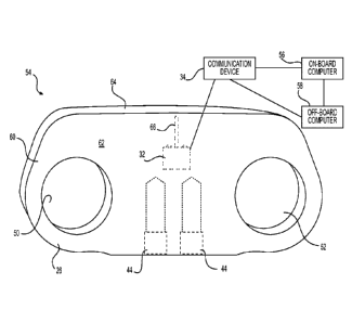
Fig. 3 illustrates an exemplary detection system 54 that includes
sensing device 32 and communication device 34. In an exemplary embodiment,
detection system 54 may also include an on-board computer 56 and an off-board
computer 58. Sensing device 32 may be mounted to a track link 26 and
configured to transmit a signal indicative of a wear parameter to
communication
CA 02958301 2017-02-16
WO 2016/032793 -9-
PCMJS2015/045603
device 34. Communication device 34 may be configured to receive the signal
and transmit a corresponding signal to on-board computer 56 and/or off-board
computer 58.
As shown in Fig. 3, sensing device 32 may be positioned on or in
a link body 60 of a track link 26, proximate to a surface 62 and a surface 64.
In
one embodiment, sensing device 32 may be positioned within a cavity formed in
surface 62 such that sensing device 32 is embedded within link body 60.
Sensing device 32 may be secured in a manner that allows signals produced by
sensing device 32 to be transmitted outside of link body 60, such as through
the
cavity, perpendicular to surface 62.
In an exemplary embodiment, sensing device 32 may be
positioned adjacent surface 64, which may be a wear surface of link body 60. A
wear surface may be any surface of link body 60 in which material wears away
during use of track assembly 12. For example, surface 64 may be a wear surface
in which material is worn away through contact with other components of track
assembly 12 (e.g., rollers 22 or other track guide) and/or external materials
(e.g.,
the ground). Sensing device 32 may be positioned adjacent surface 64 such that
sensing device 32 may be configured to detect a wear parameter of surface 64.
For example, sensing device 32 may be configured to detect an amount of
material that has been worn away from surface 64.
The manner in which sensing device 32 detects a wear parameter
may depend on the configuration of sensing device 32. Thus, it should be
understood that sensing device 32 is not limited to the configurations
described
herein, and may include other configurations that allow sensing device 32 to
detect a wear parameter of surface 64.
In one embodiment, sensing device 32 may include a wear
portion 66 positioned at surface 64 such that, as surface 64 wears away, wear
portion 66 also wears away. Sensing device 32 may be configured such that the
change in structure of wear portion 66 due to the wear of surface 64 allows
sensing device 32 to determine an amount of wear that has occurred (e.g.,
correlate a dimension, structure, and/or state of wear portion 66 with an
amount
of material at surface 64 that must have been removed to result in that
dimension, structure, and/or state).
CA 02958301 2017-02-16
WO 2016/032793 -10-
PCMJS2015/045603
In another embodiment, sensing device 32 may detect a wear
parameter by measuring a distance from a set point (e.g., an end of sensing
device 32) to surface 64. For example, sensing device 32 may use a depth
sensor
that uses ultrasonic waves, sound waves, lasers, etc. to determine a distance
from
sensing device 32 to surface 64. As surface 64 wears away, this distance will
change, and an amount of material worn away from surface 64 may therefore be
determined.
As will be described, sensing device 32 may include one or more
components (e.g., antenna, transceiver, transmitter, etc.) that are configured
to
transmit a signal indicative of a wear parameter of surface 64 to
communication
device 34. Communication device 34 may be configured to receive the signal
and transmit a corresponding signal to on-board computer 56 and/or off-board
computer 58. In one embodiment, communication device 34 may include an
antenna configured to receive a signal from one device and forward the signal
to
another device. In some embodiments, communication device 34 may also
include a processor and memory for processing and/or storage of information
(e.g., wear parameters from sensing device 32).
On-board computer 56 may be a computing device located on
machine 10 (e.g., inside the operator cabin). For example, on-board computer
56
may be a dashboard computer including at least a processor and a display. On-
board computer 56 may communicate with communication device 34 (e.g., via a
wired or wireless connection) to receive wear parameter information. On-board
computer 56 may display wear parameter information (e.g., to an operator of
machine 10).
Off-board computer 58 may be a similar computing device
located away from machine 10 (e.g., inside a control building). Off-board
computer 58 may also include at least a processor and a display. Off-board
computer 58 may be configured to communicate with communication device 34
and/or on-board computer 56 (e.g., via a wireless network) to similarly
receive
wear parameter information, which may be displayed to an operator (e.g., a
machine supervisor) away from machine 10.
Fig. 4 illustrates an exemplary embodiment of sensing device 32.
Sensing device 32 may include one or more tangible, non-transitory hardware
components, including one or more central processing units (CPUs) or
CA 02958301 2017-02-16
WO 2016/032793 -11-
PCMJS2015/045603
processors. For example, sensing device 32 may include a sensing component
68 configured to directly and/or indirectly measure, sense, and/or otherwise
receive information (e.g., a wear parameter) as input. In the embodiment of
Fig.
4, sensing component 68 may be wear portion 66, which may be a portion of
sensing device 32 that is configured to wear away with a wear surface of a
track
link 26. For example, wear portion 66 may be a resistance member (e.g., one or
more resistors) configured such that, as wear portion 66 wears away, a
resistance
value associated with the resistance member changes. This change in resistance
may be correlated with an amount of material at surface 64 that has worn away.
In other embodiments, wear portion 66 may take another configuration (e.g.,
other than being a resistance member, an alternative shape, etc.). Further, in
some embodiments, sensing component 68 may not be a wear portion, and may
be another device configured to detect a wear parameter (e.g., a depth
sensor).
Sensing device 32 may further include circuitry components 70
configured to generate, receive, transmit, and/or modify a signal indicative
of a
wear parameter detected by sensing device 32. For example, circuitry
components 70 may include a signal conditioner, an amplifier, a multiplexer,
and/or a converter (e.g., an analog-to-digital (A/D) converter or a digital-to-
analog (D/A) converter). It should be understood that these components are
exemplary and that additional and/or alternative circuitry components may be
used, depending on the configuration of sensing component 68.
A controller 72, such as a low-power microcontroller, may
provide an output in response to the input received from sensing component 68
and/or one or more signals processed by any or all of circuitry components 70.
A memory device 74, such as either or both of a random-access memory (RAM)
and a read-only memory (ROM), may store information related to one or more
of the input received from sensing component 68, one or more processed signals
from circuitry components 70, and the output from controller 72. Alternatively
or additionally, memory device 74 may store instructions used by one or more
other components of sensing device 32 (or other component of detection system
54), such as controller 72.
A transceiver 76, such as for example a radio-frequency (RF)
transceiver, may wirelessly broadcast the output provided by controller 72
(e.g.,
to communication device 34). Alternatively or additionally, an output port
(not
CA 02958301 2017-02-16
WO 2016/032793 -12-
PCMJS2015/045603
shown), such as for example a USB (universal serial bus) port or similar port,
may transmit the output provided by controller 72 through a cable or other
connection removably connected to the output port.
A power source 78 may power one or more of the components of
sensing device 32. In one embodiment, power source 78 may include a battery,
such as a coin-cell type battery. In some embodiments, power source 78 may
additionally or alternatively include a motion-based energy source, such as a
vibration-based energy-harvesting system, to power one or more of the
components of sensing device 32, and/or may be used to charge a battery of
power source 78. In yet another embodiment, power source 78 may include a
battery capable of being wirelessly charged (e.g., near-field charging). In
this
way, sensing device 32 may be embedded within link body 60 while being
capable of receiving electrical power from outside of link body 60, and thus
reducing on-board power (e.g., battery) requirements.
Although Fig. 4 shows examples of specific components used by
sensing device 32, sensing device 32 is not limited to the particular
configuration
shown. Rather, consistent with the disclosure, sensing device 32 may include
other components, more components, or fewer components than those described
above. Further, it is contemplated that one or more of the hardware components
listed above may be implemented in part or wholly using software. One or more
of such software components may be stored on a tangible, non-transitory
computer-readable storage medium that includes computer-executable
instructions that, when executed by a processor or other computer hardware,
perform methods and processes consistent with the disclosure.
Fig. 5 illustrates an exemplary track link 26 in which a sensing
device 32 has been installed. In an exemplary embodiment, track link 26 may
include a cavity 80 formed in surface 62. Cavity 80 may be sized and shaped to
receive at least a portion of sensing device 32. In some embodiments, a
passage
82 may be connected to cavity 80 and configured to receive wear portion 66 of
sensing device 32. Passage 82 may extend from cavity 80 to surface 64 such
that wear portion 66 may wear away with surface 64.
Sensing device 32 may be positioned in cavity 80 and held in
place by a containment mechanism 84. Containment mechanism 84 may be a
material, device, or system configured to hold sensing device 32 in place in
CA 02958301 2017-02-16
WO 2016/032793 -13-
PCMJS2015/045603
cavity 80. In one embodiment, containment mechanism 84 may be an encasing
material filling cavity 80, with sensing device 32 embedded therein. In
another
embodiment, containment mechanism 84 may be a housing configured to house
sensing device 32 and be received in cavity 80. In some embodiments,
containment mechanism 84 may include a cover (not shown) configured to seal
an opening into cavity 80 at surface 62. For example, sensing device 32 may be
held in place by fasteners (e.g., threaded fasteners) and a cover may close
sensing device 32 within cavity 80 to protect sensing device 32 from damage.
While cavity 80 and containment mechanism 84 are depicted and
described, it should be understood that there may be other means for mounting
sensing device 32 to track link 26. An exemplary process for mounting sensing
device 32 to track link 26 and using detection system 54 is described in more
detail below.
Industrial Applicability
The exemplary disclosed track link having a wear sensing device
may be applicable to a track assembly of any track-type machine. The track
link
and wear sensing device may be used to monitor a wear parameter associated
with the track link and automatically transmit a signal indicative of the wear
parameter to a computing device for further use. Since wear of a track link
may
be indicative of the remaining life of a machine undercarriage (e.g., a chain
assembly of the undercarriage), the disclosed embodiments may allow for a
determination of a state of a machine undercarriage (e.g., whether critical
wear
levels have been reached, structural health of the undercarriage, etc.).
Further,
monitoring of a wear parameter may allow an operator to accurately make
inventory part predictions, proactively schedule machine maintenance, and
easily and efficiently track wear rates.
In addition, the exemplary disclosed detection system, including
an embedded sensing device and strategically positioned communication device,
may allow for reliable monitoring of a wear parameter of a track link.
Positioning the sensing device within the track link protects the sensing
device
from damage during use of the associated track assembly and allows the sensing
device to be positioned adjacent a wear surface of the track link for accurate
detection of a wear parameter (e.g., through corresponding wear of a portion
of
CA 02958301 2017-02-16
WO 2016/032793 -14-
PCMJS2015/045603
the sensing device or direct measurement). An exemplary process for mounting
sensing device 32 to track link 26 will now be described.
In an exemplary embodiment, an existing (e.g., manufactured)
track link 26 may be selected and cavity 80 may be machined therein. In other
embodiments, track link 26 may be manufactured (e.g., cast, forged, 3-D
printed,
etc.) with cavity 80 formed therein. In one embodiment, cavity 80 may be
formed as a recess in outward-facing surface 38 of link body 60. In other
embodiments, cavity 80 may be located elsewhere on link body 60. Passage 82
may be machined and/or formed adjacent to cavity 80 to receive wear portion 66
of sensing device 32 (in embodiments in which sensing device 32 includes a
wear portion 66).
With cavity 80 formed in link body 60, sensing device 32 may be
placed in cavity 80 and secured therein by containment mechanism 84. In one
embodiment, containment mechanism 84 may be a material configured to fill
cavity 80 with sensing device 32 embedded therein. For example, containment
mechanism 84 may be a potting epoxy that may be poured/injected into cavity
80 with sensing device 32 positioned therein. The potting epoxy may cure to
form a solid material, thereby holding sensing device 32 in place. The
material
used to embed sensing device 32 may have sufficient strength to prevent damage
to sensing device 32 while also being capable of allowing signals to be
transmitted therethrough (such that wireless transmissions between sensing
device 32 and communication device 34 may be reliably made).
In another embodiment, containment mechanism 84 may be a
housing configured to be received in cavity 80. The housing may removably or
permanently receive and protect sensing device 32 therein and may be
removably or permanently insertable into cavity 80. In one example, the
housing may removably receive sensing device 32 therein. In addition, the
housing may be removably received in cavity 80 (e.g., the housing may include
threads, a detent mechanism, clips, etc., that mate with a corresponding
feature
of cavity 80). In this way, sensing device 32 (and/or a housing including
sensing
device 32) may be accessible (e.g., for replacement, service, wired
connection,
etc.).
As described herein, containment mechanism 84 may be
configured to allow signals produced by sensing device 32 to pass
therethrough.
CA 02958301 2017-02-16
WO 2016/032793 -15-
PCT/1JS2015/045603
For example, the material of containment mechanism 84 may be substantially
transparent to radio transmissions produced by transceiver 76. Further, when
installed on machine 10, track link 26 that includes sensing device 32 may be
positioned such that cavity 80 faces away from a center of machine 10. In this
way, an exposed portion of containment mechanism 84 may face away from
machine 10, thus allowing signals transmitted by sensing device 32 to be more
easily broadcast away from track assembly 12 (e.g., and to communication
device 34) by avoiding travel solid components of machine 10.
Sensing device 32 mounted to track link 26 may be configured to
detect a wear parameter of track link 26. For example, sensing device 32 may
include wear portion 66, which may wear away with surface 64 of link body 60
as operation of machine 10 causes such wear. The change in structure of wear
portion 66 may allow sensing device 32 to determine a wear parameter of track
link 26. For example, when a threshold amount of wear portion 66 is worn
away, sensing device 32 may be configured to detect the change and correlate
the change with a wear parameter (e.g., a particular amount of material has
worn
away from surface 64). For instance, controller 72 may detect that a structure
of
wear portion 66 has changed via circuitry components 70. In another example,
sensing device 32 may include a depth sensor configured to measure a
dimension of link body 60. Controller 72 may similarly communicate with the
depth sensor via circuitry components 70.
Controller 72 may produce a signal indicative of a detected wear
parameter. For example, controller 72 may determine that a threshold amount of
wear portion 66 has worn away, determine an amount of wear that corresponds
to the threshold, and produce a signal indicating the amount of wear. In
another
embodiment, controller 72 may directly measure the wear parameter (e.g.,
correlate a current state of wear portion 66 or use a depth sensor to measure
a
dimension from a set point to surface 64). Transceiver 76 may transmit the
signal to communication device 34. Communication device 34 may receive the
signal and forward the determined wear parameter to on-board computer 56
and/or off-board computer 58. On-board computer 56 and/or off-board
computer 58 may receive the signal and perform one or more processes to
inform an operator of the wear parameter, automatically schedule maintenance,
CA 02958301 2017-02-16
WO 2016/032793 -16-
PCMJS2015/045603
update tracked wear information, estimate a remaining life of track link 26
and/or an associated track assembly 12, etc.
Through the exemplary disclosed processes, the disclosed track
link 26 and sensing device 32 may provide automatic and/or on-demand
monitoring of a wear parameter associated with track link 26. In addition, the
use of sensing device 32 in conjunction with on-board computer 56 and/or off-
board computer 58 allows wear information to be tracked and analyzed by a
computing device and/or an operator (e.g., an operator within machine 10, a
supervising operator in a control building, etc.). In this way, track assembly
12
may be monitored and maintained without requiring inefficient manual
inspection and without relying on estimates of remaining part life.
It will be apparent to those skilled in the art that various
modifications and variations can be made to the track assembly and detection
system of the present disclosure without departing from the scope of the
disclosure. Other embodiments will be apparent to those skilled in the art
from
consideration of the specification and practice of the embodiments disclosed
herein. It is intended that the specification and examples be considered as
exemplary only, with a true scope of the disclosure being indicated by the
following claims.