Note: Descriptions are shown in the official language in which they were submitted.
LINER DRILLING USING RETRIEVABLE
BOTTOM-HOLE ASSEMBLY
TECHNICAL FIELD
[0001] The
embodiments disclosed herein relate generally to methods and systems for oil
field directional drilling. In particular, the embodiments relate to a method
for directional
liner drilling and cementing using a retrievable bottom-hole assembly.
BACKGROUND
[0002] A liner is
basically a casing string that does not extend to the top of the wellbore,
but instead is suspended from inside the bottom of the previous casing string.
In directional
liner drilling, the bore hole is drilled with the liner located above the
bottom hole drilling
assembly. The liner effectively becomes part of the drill string. Drilling
through thousands
of feet of subterranean formation may dull the drill bit, which requires the
bottom hole
drilling assembly to be brought to the surface to change the drill bit or
perform other
maintenance. When the bottom-hole assembly is tripped out of the bore hole to
retrieve the
drill bit, the liner is typically pulled out with the bottom-hole assembly.
Accordingly, what is
needed are systems and methods for retrieving the bottom-hole assembly to the
surface while
leaving the liner down hole.
SUMMARY
[0002a] In
accordance with a general aspect, there is provided a system for liner
drilling in a wellbore, comprising: a drill pipe work string including a
liner, a liner hanger
coupled to a liner hanger running tool, a reamer, and a thruster; release pins
in the liner
hanger running tool that can be sheared to de-couple the liner hanger and the
liner from the
liner hanger running tool, wherein the drill pipe work string is removed from
the borehole
while the liner remains in place; a latch coupling that couples the liner
hanger running tool to
the liner hanger when the drill pipe work string is tripped back into the
borehole so the liner
drilling can be performed using the thruster until the thruster is at full
stroke; and at least one
additional latch coupling for coupling the liner hanger running tool to the
liner hanger after
the drill pipe string is set down so that liner drilling can be performed
using the thruster until
the thruster is again at full stroke; the system further comprising a lower
latch coupling that
couples the liner hanger running tool to the liner hanger and an expansion
cone is against the
liner hanger, allowing directional liner drilling.
[0002b] In
accordance with another aspect there is provided an apparatus having a
retrievable bottom-hole assembly, comprising: a drill pipe work string
including a liner, a
1
CA 2958465 2018-06-19
liner hanger coupled to a liner hanger running tool, a reamer, and a thruster;
a shearable
release pin in the liner hanger running tool connecting the liner hanger and
liner to the liner
hanger running tool allowing the drill pipe work string to be removed from the
borehole
while the liner remains in place; a latch coupling connecting the liner hanger
running tool to
the liner hanger when the drill pipe work string is tripped back into the
borehole; and at least
one additional latch coupling for coupling the liner hanger running tool to
the liner hanger
after the drill pipe string is set down so that liner drilling can be
performed using the thruster
until the thruster is again at full stroke; the apparatus further comprising a
lower latch
coupling for coupling the liner hanger running tool to the liner hanger and an
expansion cone
is against the liner hanger, allowing directional liner drilling.
BRIEF DESCRIPTION OF DRAWINGS
[0003] FIG. 1 is a schematic diagram illustrating a directional liner
drilling operation
according to one or more embodiments of the disclosure.
[0004] FIG. 2 is a schematic diagram illustrating a directional liner
drilling operation
according to one or more embodiments of the disclosure.
[0005] FIG. 3 is a schematic diagram illustrating a directional liner
drilling operation
according to one or more embodiments of the disclosure.
[0006] FIG. 4 is a schematic diagram illustrating a directional liner
drilling operation
according to one or more embodiments of the disclosure.
[0007] FIG. 5 is a schematic diagram illustrating a directional liner
drilling operation
according to one or more embodiments of the disclosure.
[0008] FIG. 6 is a schematic diagram illustrating a directional liner
drilling operation
according to one or more embodiments of the disclosure.
1a
CA 2958465 2018-06-19
CA 02958465 2017-02-16
WO 2016/057032 PCT/US2014/059712
[0009] FIG. 7 is a schematic diagram illustrating a directional liner
drilling operation
according to one or more embodiments of the disclosure.
[0010] FIG. 8 is a schematic diagram illustrating a directional liner
drilling operation
according to one or more embodiments of the disclosure.
[0011] FIG. 9 is a schematic diagram illustrating a directional liner
drilling operation
according to one or more embodiments of the disclosure.
[0012] FIG. 10 is a schematic diagram illustrating an operation for
directional liner
drilling cementing, according to one or more embodiments of the disclosure.
[0013] FIG. 11 is a schematic diagram illustrating an operation for
directional liner
drilling cementing, according to one or more embodiments of the disclosure.
[0014] FIG. 12 is a schematic diagram illustrating an operation for
directional liner
drilling cementing, according to one or more embodiments of the disclosure.
[0015] FIG. 13 is a schematic diagram illustrating an operation for
directional liner
drilling cementing, according to one or more embodiments of the disclosure.
[0016] FIG. 14 is a schematic diagram illustrating an operation for
directional liner
drilling cementing, according to one or more embodiments of the disclosure.
[0017] FIG. 15 is a schematic diagram illustrating an operation for
directional liner
drilling cementing, according to one or more embodiments of the disclosure.
[0018[ FIGS. 16A ¨ 16E are cutaway views of a liner hanger system
according to one
or more embodiments of the disclosure.
[0019] FIG. 17 is a perspective view showing a latch coupling according
to one or
more embodiments of the disclosure.
[0020] FIG. 18 is a perspective view showing a latch coupling according
to one or
more embodiments of the disclosure.
[0021] FIG. 19 is a cross-sectional view of a lug arrangement used in a
liner hanger
system according to one or more embodiments of the disclosure.
[0022] FIGS. 20A ¨ 20E are flowcharts illustrating a method for
directional liner
drilling and cementing according to one or more embodiments of the disclosure.
DETAILED DESCRIPTION OF DISCLOSED EMBODIMENTS
[0023] As an initial matter, it will be appreciated that the development of
an actual,
real commercial application incorporating aspects of the disclosed embodiments
will
require many implementation-specific decisions to achieve the developer's
ultimate goal
2
CA 02958465 2017-02-16
WO 2016/057032 PCT/US2014/059712
for the commercial embodiment. Such implementation-specific decisions may
include,
and likely are not limited to, compliance with system-related, business-
related,
government-related and other constraints, which may vary by specific
implementation,
location and from time to time. While a developer's efforts might be complex
and
time-consuming in an absolute sense, such efforts would nevertheless be a
routine
undertaking for those of skill in this art having the benefit of this
disclosure.
[0024] It
should also be understood that the embodiments disclosed and taught herein
are susceptible to numerous and various modifications and alternative forms.
Thus, the
use of a singular term, such as, but not limited to, "a" and the like, is not
intended as
limiting of the number of items. Similarly, any relational terms, such as, but
not limited
to, "top," "bottom," "left," "right," "upper," "lower," "down," "up," "side,"
and the like,
used in the written description are for clarity in specific reference to the
drawings and are
not intended to limit the scope of the invention.
[0025] As
mentioned above, the embodiments disclosed herein relate to directional
liner drilling and cementing using a retrievable bottom-hole assembly.
According to one
or more embodiments, a method is provided that allows the running of a liner
into a
borehole while directionally drilling a new borehole. The liner may be placed
downhole
and left in position while the directional drilling bottom-hole assembly is
brought to the
surface to change the drill bit or perform other maintenance. The operator may
then re-
enter the liner with the bottom-hole assembly and subsequently re-attach the
bottom-hole
assembly to the liner and continue drilling the borehole. Leaving the liner in
place at the
bottom of the borehole helps protect that portion of the borehole from
collapsing or
otherwise filling up with debris or formation material that may prevent or
make it more
difficult to properly case off that portion of the borehole.
[0026] In one
implementation, a drill pipe work string is attached to a liner hanger and
a liner hanger running tool. The liner hanger may be an expandable liner
hanger in some
implementations and may also include a packer in some implementations, while
the liner
hanger running tool may be an expandable liner hanger running tool in some
implementations, without departing from the scope of the disclosed
embodiments. A
tailpipe, an inner string below the liner hanger running tool, may be attached
below, or
downhole of, the expandable liner hanger and packer running tool. The drill
pipe work
string may also include a thruster tool and a directional drilling assembly.
The liner is
attached to the expandable liner hanger and packer. In one embodiment, the
liner or any
3
CA 02958465 2017-02-16
WO 2016/057032 PCT/US2014/059712
suitable liner tubular or tubular system may be continuous and made from any
suitable
materials such as metals, plastics, composites, etc. In various embodiments
the liner may
be segmented or contain sliding sleeve subs and/or packers. The expandable
liner hanger
and packer is attached to the expandable liner hanger and packer running tool
with a
latch. The directional drilling assembly is located at the bottom of the liner
with a no-go
shoulder and attached to the bottom of the liner with a latch.
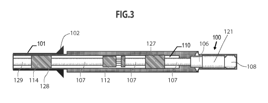
[0027] Reference is now made to FIGS. 1 ¨ 10, which are cross-sectional
views
showing a drilling work string or drill string having a bottom-hole assembly
("BHA") 100
in a section of casing 101 and a liner 110, as they would appear at the
beginning of
directional liner drilling according to an embodiment of the disclosure. As
shown in
FIG. 1, the BHA 100 may include reamer 106, drill bit 108, and other BHA
components
121, such as mud motors, measurement-while-drilling (MWD) or logging-while-
drilling
(LWD) tools, or other similar tools familiar to those of skill in the art. As
FIG. 3 shows,
the drilling work string further includes drill pipe 129, which is located
above a liner
hanger running tool 114 and sections of an inner work string 107. A thruster
112 is
mounted on the inner work string 107, which is part of an expandable liner
hanger
running tool assembly 103 (shown in FIGS. 16A, 16B), that includes the
combination of a
liner hanger running tool 114 and an expandable liner hanger and packer 128.
[0028[ In general operation, an operator initially uses the drilling
work string to
directionally liner drill out of a casing shoe 102, creating a borehole 104.
The borehole
104 is typically filled with drilling mud 105. After drilling has advanced far
enough out
of the casing shoe 102, the reamer 106 is opened to enlarge the borehole 104
as shown in
FIG. 2. The borehole 104 should be enlarged to a diameter greater than the
diameter of
the drill bit 108 and the liner 110. The operator may then continue
directionally drilling
the borehole through the liner 110, as shown in FIG. 3.
[0029] Eventually, however, the demands of drilling through the rock
formation are
likely to cause the drill bit 108 to become dull or cause the need for other
maintenance to
be performed on the drill pipe work string. Some maintenance operations may
require the
drill pipe work string to be removed or "tripped" from the borehole.
[0030] When the drill pipe work string is to be removed, according to one
implementation, the liner 110 may be set on the bottom of the borehole 104 as
shown in
FIG. 4. After setting the liner 110 on the bottom, release pins may be sheared
to allow
the liner hanger running tool 114 to disengage from the expandable liner
hanger and
4
CA 02958465 2017-02-16
WO 2016/057032 PCT/US2014/059712
packer. Other release mechanisms besides the release pins may be used without
departing
from the scope of the disclosed embodiments. As mentioned above, the liner
hanger
running tool 114 may be part of an expandable liner hanger running tool
assembly 103
that is described in detail in FIGS. 16A ¨ 16E. In the embodiment shown in
FIGS. 1 ¨
10, a fluid seal 127 is provided between the thruster 112 and the BHA 100 to
prevent
wellbore fluid and formation debris from getting inside the liner 110.
Instead, wellbore
fluid, or mud 105, should flow from the drill bit 108 back up through the
wellbore 104.
In another embodiment, particularly useful if the expandable liner hanger
running tool
assembly 103 is long, the fluid seal 127 may also include one or more latches
that operate
in a similar manner to the operation of the latches described below in
connection with
FIGS. 16A¨ 16E and 17.
[0031] FIGS. 16A ¨ 16E show a cutaway view of an expandable liner hanger
running
tool assembly 103. In FIGS. 16A ¨ 16E, the uphole end closest the surface of
the
assembly is depicted on the left side of the figure, while the downhole end of
the
assembly is depicted on the right. The expandable liner hanger running tool
assembly
103 comprises the inner work string 107 mentioned above and an outer work
string 109.
Both the inner string 107 and the outer string 109 of the expandable liner
hanger running
tool assembly 103 may include various components, which will be further
described in
connection with FIGS. 16A ¨ 16E. FIG. 16C shows a cutaway view of a lower
section of
the expandable liner hanger running tool assembly 103 having an expansion cone
140 and
expansion sleeve 141. In some embodiments, this section is arranged downhole
of the
section shown in FIG. 16A. FIG. 16B shows another section of the expandable
liner
hanger running tool assembly 103, including a latch 136 for engaging the outer
string 109
of the expandable liner hanger running tool assembly 103. The section shown in
FIG.
16B may be arranged downhole of the section shown in FIG. 16C.
[0032] FIG.
16D shows a cutaway view of the expandable liner hanger and packer 128
referenced above. The expandable liner hanger and packer 128 is arranged as a
sleeve
over inner string mandrel 113, which serves to transfer tensile loads, shown
in FIG. 16C,
so that the upper end of the expandable liner hanger and packer 128 is
immediately
downhole of expansion cone 140.
[0033] FIG.
16E shows a cutaway view of an outer sleeve section 117 of the
expandable liner hanger running tool assembly 103. The outer sleeve section
117 is part
of the outer string of expandable liner hanger running tool assembly 103, and
includes
5
CA 02958465 2017-02-16
WO 2016/057032 PCT/US2014/059712
latch couplings 130, 132, and 134 spaced a predefined distance from each
other, which
engages the latch 136 on the inner string of the expandable liner hanger
running tool
assembly 103, shown in FIG. 16B. Outer sleeve section 117 is positioned
immediately
downhole of the expandable liner hanger and packer 128, shown in FIG. 16D.
Liner 110
is attached to the outer sleeve 117, and may include additional components,
such as
centralizer 119, sliding sleeve subs, packers, etc.
[0034]
FIGS. 16A and 19, illustrate the operation of the release pins according to an
embodiment of the disclosure. In this embodiment, release pins 126 are
provided in the
expandable liner hanger running tool 114 to engage it with the expandable
liner hanger
and packer. Release pins 126 may be sheared in the expandable liner hanger
running tool
114, allowing it to disengage from the expandable liner hanger and packer 128
as shown
in FIG. 16A. As shown in FIG. 19, a lug 144 is disposed in a H-slot 146 and is
in
position 152 when in tension and moves down into position 154 when in
compression.
Lug 144 is part of lug body 148, as shown in FIG. 16A, which connects to the
drill pipe
string. H-slot 146 is part of H-slot mandrel 150. Lug 144 can move between
position
152 and position 154 without shearing pins 126. To shear pins 126, the drill
pipe string is
put in tension to put lug 144 into position 152, then the drill pipe string is
rotated left,
counter clockwise, and next set into compression which moves lug 144 into
position 156.
The lug body 148 travels downward and contacts shear sleeve 158 and then the
shear pins
126 are sheared. Additional downward movement pushes the latch 136 down and
out of
the lowest latch coupling 134, as shown in FIGS. 16A ¨ 16B. This frees the
directional
liner drilling work string and allows it to be tripped out of, or removed
from, the
borehole.
[0035] The
drill pipe work string may then be tripped out of the borehole 104,
leaving the liner 110 in place as shown in FIG. 5. The liner 110 is attached
to expandable
liner hanger and packer 128, which includes a plurality of latch couplings
130, 132, and
134 spaced a predefined distance from each other. The drill bit may be
replaced, or other
operations may be performed on the drill pipe work string at the surface.
[0036] It
will be recognized that one drawback to removing the drill pipe work string
from the bore hole is that a portion of the borehole below the liner may
collapse or rock
formation cuttings may settle into the bottom of the borehole 104. FIG. 5
shows a cross-
section of the borehole with the liner 110 set on the bottom of the borehole
104.
6
CA 02958465 2017-02-16
WO 2016/057032 PCT/US2014/059712
Although not expressly shown, a portion of the recently-drilled, but not
reamed, borehole
104 may be filled in by cuttings.
[0037] With reference now to FIG. 6, when the drill pipe work string is
run back into
the bore hole, the expandable liner hanger running tool 114 is first engaged
with the first,
or upper, latch coupling 130 of the expandable liner hanger and packer 128.
[0038] Once engaged, the liner 110 may then be picked up off the bottom
of the
borehole 104 and rotated. Drilling fluid is then pumped into the drill pipe
work string to
activate a thruster 112. The thruster is activated and deactivated with
hydraulic pressure
through fluid ports. In various embodiments the fluid ports are always open or
opened
and closed selectively by mud pulse signals, slick line intervention, wire
line intervention,
etc. The thruster 112 applies force to the drill bit 108, while the downhole
motor spins to
drill out the portion of the borehole below the liner 110, which may or may
not be
collapsed. Drilling may be continued until the thruster 112 reaches full
stroke, as seen in
FIG. 7.
[0039] FIG. 17 shows a latch coupling according to an embodiment of the
disclosure.
The latch 1701 includes a series of engagement surfaces that are carried on a
latch
mandrel 1702. The latch 1701 and latch mandrel 1702 fit within latch coupling
1703.
Latch coupling 1703 is provided with a series of engagement grooves that
correspond to
the engagement surfaces on latch 1701. When the latch 1701 is engaged, the
latch
engagement surfaces move radially outward to engage with the corresponding
latch
grooves on latch coupling 1703. FIG. 18 shows a latch coupling according to
another
implementation of the disclosure. Though the arrangement of the engagement
surfaces is
different, the latch 1801 similarly is carried on latch mandrel 1802 and
engages with
grooves provided on latch coupling 1803. Of course, other coupling mechanisms
may be
used besides the latch coupling shown here without departing from the scope of
the
disclosed embodiments.
[0040] As shown in FIGS. 6 and 7, after the thruster 112 reaches full
stroke with the
first latch coupling 130 engaged, the drill pipe work string is then lowered
in the borehole
until the second latch of the expandable liner hanger running tool 114 engages
with the
second latch coupling 132. Once the second latch coupling is engaged, then
directional
liner drilling is resumed using the thruster 112 until it is again at the full
stroke, as shown
in FIG. 8. This process may be repeated until the expandable liner hanger
running tool
7
CA 02958465 2017-02-16
WO 2016/057032 PCT/US2014/059712
114 engages the lowest latch coupling 134 and the expansion cone no-go is
against the
expandable liner hanger and packer 128.
[0041] FIGS. 16C ¨ 16D illustrate the operation of the expansion cone in
more detail.
The expansion cone 140 may be moved downward, toward the bit, through
expandable
liner hanger and packer 128 until contacting the no-go shoulder 142 inside the
expandable
liner hanger and packer 128. The portion of the expandable liner hanger and
packer 128
above the no-go shoulder 142 is expanded radially outward by the force of the
expansion
cone 140. The expansion cone 140 and no-go shoulder 142 are conically locked
due to
sharing the same radial and angular profile.
[0042] FIG. 9 is a cross-sectional view of the drill pipe work string
positioned in the
well bore 104 after the lowest latch coupling is engaged with the expandable
liner hanger
running tool 114 and the expansion cone no-go against the liner hanger.
Although three
latch couplings are depicted in the embodiment shown, the number of latch
couplings and
spacing may be adjusted based on the length of thruster stroke and length of
bottom hole
drilling assembly stickout outside of the bottom of the liner.
[0043] The liner hanger running tool is now torsionally locked to the
liner at the latch
and latch coupling interface and will transmit tensile forces from the liner
to the drill pipe
string through this same latch and latch coupling interface, and will transmit
compression
forces from the drill pipe string to the liner through the expansion cone and
no-go
shoulder interface. At this point, the expandable liner hanger running tool
114 would be
fully engaged into the expandable liner hanger and packer and directional
drilling may
continue to total depth.
[0044] Once total depth is reached, the liner will be in the correct
position for final
installation in the borehole. Embodiments of final installation may be
applicable to
injection wells as well as production wells, including hydrocarbon wells. In
various
embodiments, the liner may contain sliding sleeve subs and/or packers. The
packers may
be set mechanically, electronically, or after pumping an activation fluid and
allowing the
packers to swell. In various embodiments, cementing of the liner, which may or
may not
contain sliding sleeve subs, may be performed upon reaching total depth with
the same
directional drilling bottom-hole assembly still in hole. In other embodiments,
cementing
of the liner may be performed using a different cementing tool string. The
expandable
liner hanger running tool 114 may then be set down on the bottom of the
borehole, and
the release pins 126 in expandable liner running tool sheared.
8
CA 02958465 2017-02-16
WO 2016/057032 PCT/US2014/059712
[0045] With
reference now to FIGS. 10 ¨ 12, after the work string is out of the
borehole 104, the cementing work string is then picked up and tripped into the
borehole.
Figures 11-14 show a cross-sectional view of a borehole with the cementing
work string
116 positioned in the borehole 104. In one embodiment of the disclosure, the
cementing
work string 116 includes the expandable liner hanger and packer running tool,
a top liner
wiper plug 118, and a pumpable float valve 120. In another embodiment of the
disclosure, the cementing work string 116 includes the expandable liner hanger
and
packer running tool, a top liner wiper plug 118, a bottom wiper plug (not
shown), and a
pumpable float valve 120. The expandable liner hanger running tool 114 latch
then
engages the latch coupling in the expandable liner hanger and packer and picks
the liner
off the bottom of the hole, as shown in FIG. 11. The liner can now be rotated
and
reciprocated during the cementing operations. A ball or dart is then released
at the
surface and pumped down the drill pipe until it engages the pumpable float
valve 120.
This releases the pumpable float valve 120 from the bottom of the liner wiper
plug 118.
The float valve may then be pumped to the bottom of the liner where it engages
a no-go
latch shoulder 122. This is best seen in the cross-sectional view of the
borehole 104 as
shown in FIG. 12. The fluid pressure in the casing string is then increased to
firmly seat
the float valve in place.
[0046[ With
reference to FIG. 13, pumping of the cement begins and continues until
the annulus around the casing in the borehole 104 is sufficiently filled with
cement 124.
The liner can be rotated and/or reciprocated at this time. A drill pipe dart,
such as dart
125 shown in FIG. 16B, may then be released at the surface and pumped down the
drill
pipe until it engages and releases the top wiper plug 118 from the bottom of
the
expandable liner hanger running tool 114. With reference to FIG.14, pumping is
continued until the top liner wiper plug 118 engages the top of the pumpable
float valve
120. At this point, the cement is fully displaced outside the liner. Next,
fluid pressure in
the liner string is increased to set and expand the expandable liner hanger
and packer. It
is often advantageous to perform a pull test at this point to ensure that all
steps have gone
correctly. Next, the drill pipe weight may be set down to release the
expandable liner
hanger running tool 114 from the expandable liner hanger. The cementing work
string is
then tripped out of hole, leaving the liner in place, as shown in FIG. 15, and
the well
ready for next operational step. This embodiment of the disclosure allows for
directional
9
CA 02958465 2017-02-16
WO 2016/057032 PCT/US2014/059712
liner drilling and the changing drill bits, or other procedures, without
pulling the liner
fully back to the surface.
[0047] In
another embodiment of the disclosure, a method is provided for liner drilling
in a wellbore that includes drilling new borehole at the base a casing shoe
using a drill
pipe work string having a liner coupled to an expandable liner hanger and
packer attached
to an expandable liner hanger and packer running tool. It may also include
reaming at
least a portion of the new borehole to enlarge the diameter of the borehole,
and setting the
liner on the bottom of the reamed portion of the borehole. Release pins may be
sheared in
the expandable liner hanger running tool 114 to de-couple the expandable liner
hanger
and packer from the expandable liner hanger running tool 114. The drill pipe
work string
may then be removed from the borehole, leaving the liner in place. The drill
bit may be
replaced on the surface, then the drill pipe work string tripped back into the
borehole.
When the drill pipe work string is tripped back into the borehole, the
expandable liner
hanger running tool 114 engages a first, or upper, latch coupling to couple
the expandable
liner hanger running tool with the expandable liner hanger and packer and
liner.
[0048] In a
further embodiment, the disclosure provides a method for liner drilling in
a wellbore. The method includes drilling new borehole at the base of a casing
shoe using
a drill bit attached to the bottom of a drill pipe work string having a liner
attached to an
expandable liner hanger and packer and coupled to a running tool, reaming at
least a
portion of the new borehole to enlarge the diameter of the borehole, and
setting the liner
on the bottom of the reamed portion of the borehole. The method also may
include
shearing release pins in the expandable liner hanger running tool to de-couple
the
expandable liner hanger and packer from the expandable liner hanger running
tool, then
removing the drill pipe work string from the borehole, leaving the liner in
place. Next,
the method may include returning the drill pipe work string back into the
borehole,
engaging a latch coupling to couple the expandable liner hanger running tool
with the
liner, raising the liner off the bottom of the reamed portion of the borehole,
and using a
thruster to drill into the borehole until the thruster is at full stroke. Once
the thruster
reaches full stroke, the method may include setting the drill pipe string down
until a next
latch coupling is engaged between the expandable liner hanger running tool and
the
expandable liner hanger and packer, and drilling until the thruster is at full
stroke.
[0049] The
previous steps may be repeated until a lowest latch coupling is engaged
between the expandable liner hanger running tool and the expandable liner
hanger and
CA 02958465 2017-02-16
WO 2016/057032 PCT/US2014/059712
packer and an expansion cone no-go is against the liner hanger. Liner drilling
may
continue until target depth is reached.
[0050]
FIGS. 20A-20E are a flow chart illustrating a method for directional liner
drilling and cementing according to an embodiment of the disclosure. With
reference to
FIG. 20A, the method begins with directional liner drilling a new bore hole.
In step 201,
the method begins by starting the directional liner drill-out of the previous
casing shoe.
Next, in step 202, the reamer is opened in order to enlarge the hole, and
directional liner
drilling is continued. After a while, the bit may become dull and need to be
replaced.
Therefore, in step 203, the operator performs a bit trip to bring the bit out
of the hole for
replacement. With reference now to FIG. 20B, in step 204, the operator sets
the liner on
the bottom of the hole, shears the release pins in the running tool, such as
the VersaFlex0
Expandable Liner Hanger ("ELH") running tool available from Halliburton Energy
Services, Inc., and trips the string out of the hole. Next, in step 205, the
hole may have
closed in or cuttings may have settled into the bottom of the hole. These need
to be
removed before continuing the next step. Therefore, in step 206, the operator
engages the
first latch coupling with the ELH running tool, picks the string off the
bottom of the hole,
and uses the thruster to drill out the hole. The operator may continue to use
the thruster to
drill out the hole until the thruster reaches full stroke. Referring now to
FIG 20C, in step
207, the operator may set the drill pipe string down until the next latch
coupling is
engaged with the ELH running tool. In step 208, the operator may drill until
the thruster
is again at full stroke. In step 209, the operator may set the drill pipe
string down until
the lowest latch coupling is engaged with the ELH running tool and the
expansion cone
"no-go" is against the liner hanger. In this configuration, the operator may
continue
directional liner drilling until total depth is reached.
[0051] FIG. 20D is a
flow chart illustrating a method for directional liner drilling and
cementing according to an embodiment of the disclosure. In step 210, total
depth has
been reached with the directional liner drilling ("DLD") assembly. The
assembly is then
set down on the bottom shear release pins in the ELH running tool, and the DLD
work
string is tripped out of the hole. In step 211, the operator may trip-in-hole
("TIH") with
the ELH running tool, top plug, and pumpable float. The operator may then
engage the
liner and pick it off the bottom. In step 212, the operator may drop a ball or
dart to
release the pumpable float. The float then engages a no-go latch. The operator
may then
pressure up to open the ball scat or dart catcher and allow fluid to flow
through the float.
11
CA 02958465 2017-02-16
WO 2016/057032 PCT/US2014/059712
Referring now to FIG. 20E, in step 213, the operator may start pumping cement,
launch
the dart, release the top wiper plug, and start displacing the cement. Next,
in step 214, the
operator may bump the wiper plug, set and expand the ELH liner hanger, and
perform a
pull test and release. If the test is successful, the operator may trip out of
hole ("TOOH").
Then, in step 215, the well is ready for the next operation step.
[0052] In yet a further embodiment, an apparatus according to the
disclosure is
conveyed into the hole on a drill pipe. Hanging from the bottom joint of the
drill pipe
begins an inner and outer string. The inner string is the service string, and
the other string
is the open hole completion string referred to herein as the liner. The inner
service string
may start with an expandable liner hanger running and setting tool with drill
pipe hanging
below it connected to a thruster device, a floating seal and/or lower latch,
then a drill pipe
dart and burst disk subs and a directional drilling assembly. The outer liner
string may
start with an expandable liner hanger and packer. Below it may hang latch
couplings,
with a number of sliding sleeve devices (there might be a number of open hole
packers
above and below each sliding sleeve device in some embodiments), then a no-go
and/or
latch collar, and a quick trip valve at the bottom of the liner. For short
liners, the
apparatus may require only a floating seal on the inner string and a no-go
collar at the
bottom of the outer string to prevent a fluid flow path in the annulus between
the inner
diameter of the outer string and the OD of the inner string. For long liners,
due to the
different torsional properties of the inner string and outer string, a lower
latch coupling
with seal may be required to prevent any trapped torque from backing off inner
or outer
string thread connections.
[0053] In one implementation, the directional liner drilling assembly
may be run in
hole, beginning by drilling out the previous casing shoe. Once the drilling
bottom-hole
assembly has drilled enough hole, the under reamer may activated and the
directional well
path is drilled and total depth is reached. The under reamer may then be
retracted.
Circulation may be established at bottom prior to starting the cementing
operation.
[0054] The cement may be mixed at the surface. The bottom drill pipe
wiper dart may
then be released from the plug dropping container at surface, and the bottom
drill pipe
dart may be pumped downhole with cement following it. After all the cement has
been
pumped, a second top drill pipe wiper dart is released from the plug dropping
container at
surface, and the cement is pumped and displaced downhole. The bottom drill
pipe wiper
dart lands in a dart catcher sub, and a rupture disk ruptures, allowing the
cement to be
12
CA 02958465 2017-02-16
WO 2016/057032 PCT/US2014/059712
pumped and displaced into the annulus between the open hole ID and the outer
liner
string. Cement displacement continues until the top drill pipe wiper dart
lands in a
second dart catcher sub. This completes the cementing displacement. Pressure
may then
be applied down the drill pipe string to set and expand the expandable liner
hanger and
packer at the top of the liner string.
[0055] The
drill pipe string is picked up to perform a pull test on the set expandable
liner hanger packer, and then slack off weight is applied to the drill pipe to
set the
expandable liner hanger running and setting tool into compression to decouple
the inner
string from the outer string at the latch coupling.
[0056] The drill pipe
string is then picked up, which pulls the entire inner string
upward. After the drill bit is pulled inside the liner shoe and above the
quick trip valve,
the quick trip valve is closed to keep the cement in place and prevent it from
flowing back
inside the liner. With the quick trip valve closed, pressure may be applied to
a second
rupture disk at the bottom of the inner string. Forward or reverse circulation
can be
established at this time, and any excess cement can be pumped out of hole, or
the well can
be swapped over to completion fluid. A mechanical shifting tool may be run to
open the
sliding sleeves and allow for hydraulic fracturing operations, or if Remote
Open Close
Technology (eREDO), available from Halliburton Energy Services, Inc., is
implemented,
the sleeves may be opened interventionless.
[0057] Accordingly,
as set forth above, the embodiments disclosed herein may be
implemented in a number of ways. In general, in one aspect, the disclosed
embodiments
relate to a method for liner drilling in a wellbore. The method comprises,
among other
things, drilling a borehole using a drill pipe work string having a liner
attached to a liner
hanger on the work string, the liner hanger coupled to a liner hanger running
tool on the
work string, reaming at least a portion of the borehole to enlarge a diameter
of the
borehole, and setting the liner in the reamed portion of the borehole. In some
embodiments, the liner hanger may be an expandable liner hanger that may also
include a
packer, and the liner hanger running tool may be an expandable liner hanger
running tool.
The method additionally comprises de-coupling the liner hanger from the liner
hanger
running tool, removing the drill pipe work string from the borehole while
leaving the liner
in place in the reamed portion of the borehole. The drill pipe work string is
then returned
back into the borehole and the liner hanger running tool is coupled with the
liner.
13
CA 02958465 2017-02-16
WO 2016/057032 PCT/US2014/059712
[0058] In
one or more embodiments, the method for liner drilling may further
comprise any one of the following features individually or any two or more of
these
features in combination: (a) raising the liner in the reamed portion of the
borehole,
drilling into the borehole a predefined distance, setting the drill pipe
string down a preset
distance, and repeating the previous steps until a drilling target is reached
in the wellbore;
(b) cementing the liner in place in the borehole, wherein cementing the liner
in place
comprises (i) setting the expandable liner on the bottom of the borehole, (ii)
de-coupling
the liner hanger running tool from the liner hanger, (iii) removing the drill
pipe work
string out of the borehole, (iv) tripping into the borehole with a work string
including a
liner hanger running tool, a top plug, and/or a bottom plug, and a pumpable
float valve,
(v) coupling the liner hanger running tool to the liner hanger and picking the
liner off the
bottom of the borehole, (vi) releasing the pumpable float valve, pumping
cement through
the pumpable float valve, and (vii) expanding the liner hanger and tripping
the liner
hanger running tool out of the borehole; and (c) the liner hanger is coupled
with the liner
by engaging a latch coupling, the borehole is drilled using a thruster until
the thruster is at
full stroke, the drill pipe string is set down a preset distance by setting
the drill pipe down
until a next latch coupling is engaged between the liner hanger running tool
and the liner
hanger, and drilling until the thruster is at full stroke, and the raising,
drilling, and setting
steps are repeated until a lowest latch coupling is engaged between the liner
hanger
running tool and the liner hanger and an expansion cone no-go is against the
liner hanger.
[0059] In
general, in another aspect, the disclosed embodiments relate to a system for
liner drilling in a wellbore. The system comprises, among other things, a
drill pipe work
string including a liner, a liner hanger coupled to a liner hanger running
tool, a reamer,
and a thruster. As mentioned above, in some embodiments, the liner hanger may
be an
expandable liner hanger that may also include a packer, and the liner hanger
running tool
may be an expandable liner hanger running tool. The system additionally
comprises
release pins in the liner hanger running tool that can be sheared to de-couple
the liner
hanger and the liner from the liner hanger running tool, wherein the drill
pipe work string
is removed from the borehole while the liner remains in place. A latch
coupling couples
the liner hanger running tool to the liner hanger when the drill pipe work
string is tripped
back into the borehole so the liner drilling can be performed using the
thruster until the
thruster is at full stroke.
14
CA 02958465 2017-02-16
WO 2016/057032 PCT/US2014/059712
[0060] In
one or more embodiments, the system for liner drilling in a wellbore may
further comprise any one of the following features individually or any two or
more of
these features in combination: (a) at least one additional latch coupling for
coupling the
liner hanger running tool to the liner hanger after the drill pipe string is
set down so that
liner drilling can be performed using the thruster until the thruster is again
at full stroke;
(c) a lower latch coupling that couples the liner hanger running tool to the
liner hanger
and an expansion cone no-go is against the liner hanger, allowing directional
liner
drilling; (c) a drill bit; (d) mud motor; (e) a directional drilling assembly;
and (f) a
bottom-hole assembly.
[0061] In general, in
yet another aspect, the disclosed embodiments relate to an
apparatus having a retrievable bottom-hole assembly. The apparatus comprises,
among
other things, a liner hanger coupled to a liner hanger running tool, a reamer,
and a
thruster. As set forth above, in some embodiments, the liner hanger may be an
expandable liner hanger that may also include a packer, and the liner hanger
running tool
may be an expandable liner hanger running tool. The apparatus additionally
comprises a
shearable release pin in the liner hanger running tool connecting the liner
hanger and liner
to the liner hanger running tool allowing the drill pipe work string to be
removed from the
borehole while the liner remains in place. A latch coupling connects the liner
hanger
running tool to the liner hanger when the drill pipe work string is tripped
back into the
borehole.
[0062] In
one or more embodiments, the apparatus having a retrievable bottom-hole
assembly may further comprise any one of the following features individually
or any two
or more of these features in combination: (a) at least one additional latch
coupling for
coupling the liner hanger running tool to the liner hanger after the drill
pipe string is set
down so that liner drilling can be performed using the thruster until the
thruster is again at
full stroke; (b) a lower latch coupling for coupling the liner hanger running
tool to the
liner hanger and an expansion cone no-go is against the liner hanger, allowing
directional
liner drilling; (c) the drill pipe work string is independently removable from
the borehole
when the shearable release pin disconnects the liner; (d) the thruster
performs liner
drilling until the thruster is at full stroke; (e) a directional drilling
assembly; (f) an H-slot
mandrel having an H-slot; and (g) a lug is provided in the H-slot.
[0063] In
general, in still another aspect, the disclosed embodiments relate to a method
of cementing a liner in a borehole. The method comprises, among other things,
tripping a
CA 02958465 2017-02-16
WO 2016/057032 PCT/US2014/059712
drill pipe work string into the borehole, the drill pipe work string including
a liner hanger
running tool, a top plug, and/or a bottom plug, and a float valve. The method
additionally
comprises coupling the liner hanger running tool to a liner hanger coupled
with the liner,
raising the liner in the borehole by a predefined distance, releasing the
float valve, and
pumping cement through the float valve.
[0064] In
one or more embodiments, the method of cementing a liner in a borehole
may further comprise any one of the following features individually or any two
or more
of these features in combination: (a) expanding the liner hanger in the
borehole and
tripping drill pipe work string including the liner hanger running tool out of
the borehole;
(b) the liner hanger is coupled with the liner by engaging a latch coupling,
(c) the liner
hanger is an expandable liner hanger, and (d) the liner hanger running tool is
an
expandable liner hanger running tool.
[0065]
While the disclosed embodiments have been described with reference to one or
more particular implementations, those skilled in the art will recognize that
many changes
may be made thereto without departing from the spirit and scope of the
description.
Accordingly, each of these embodiments and obvious variations thereof is
contemplated
as falling within the spirit and scope of the claimed invention, which is set
forth in the
following claims.
16