Note: Descriptions are shown in the official language in which they were submitted.
CA 02958474 2017-02-16
Electrochemical device for storing electrical energy and producing
hydrogen, and method for producing hydrogen
Field of the invention
The invention relates to an electrochemical device for electric power storage
and for hydrogen production and to a hydrogen production method.
State of the art
The stakes involved in bulk storage of electric power are considerable. It is
in
fact essential to have storage units able to operate over a very wide power
and
capacity range while at the same time privileging reduced volume aspects.
One promising way for storing such energies is the electrochemical channel. At
the present time, the most efficient and most dependable electrochemical
technology is that of electrolysis of non-ferrous metals in an aqueous medium,
and more particularly electrolysis of metals which have a high energy content
such as zinc or manganese.
The technology is moreover simple and inexpensive: it would therefore be
advantageous to be able to make such an electrolysis operate in reversible
manner.
Application WO 2011/015723 describes a simultaneous electric power and
hydrogen cogeneration method by totally electrochemical means. The method
comprises an electricity storage phase by electrolysis of a solution of an
electrolyzable metal and formation of an electrolyzable metal-hydrogen
battery,
and an electricity recovery and hydrogen generation phase by operation of said
battery.
CA 02958474 2017-02-16
2
However, in such devices, the volumes of the reactors are very large in order
to
be able to provide a large quantity of electric power.
Furthermore, for high-power applications, the metallic deposits are often
inhomogeneous, which reduces the electrochemical performances of the
devices and even causes short-circuiting of the electrodes by formation of
metallic dendrites.
Object of the invention
The object of the invention is to remedy the shortcomings of the prior art,
and in
particular to propose a device enabling a large quantity of electric power to
be
stored.
This object tends to be achieved by the appended claims.
Brief description of the drawings
Other advantages and features will become more clearly apparent from the
following description of particular embodiments of the invention given for non-
restrictive example purposes only and represented in the appended drawings,
in which:
- figure 1 represents a schematic view, in cross-section, of a reactor of an
electrochemical device according to an embodiment of the invention,
- figure 2 schematically represents, in top view, a stack of electrodes of a
reactor of an electrochemical device according to the invention,
- figure 3 represents a schematic view, in cross-section, of a reactor of an
electrochemical device according to another embodiment of the invention,
CA 02958474 2017-02-16
3
- figure 4 schematically represents, in top view, an electrochemical device
comprising several reactors, according to another embodiment of the invention,
- figure 5 schematically represents an electric coupling of two reactors,
according to an embodiment of the invention.
Description of a preferred embodiment of the invention
The invention relates to an electrochemical device for storing electric power
in
direct and reversible manner.
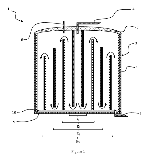
As represented in figure 1, the reversible electrochemical device 1,
configured
for electric power storage and for hydrogen production, comprises:
- a reactor 2, the wall of the reactor advantageously forming a first
electrode 3,
the reactor 2 being provided with an electrolyte input 4 and an electrolyte
output 5,
- a central electrode 6 located in the centre of the reactor 2, the
central
electrode 6 being substantially parallel to the wall of the reactor 2,
- additional electrodes Ex, with x an integer ranging from 1 to n,
the additional electrodes Ex being tubular and arranged around the central
electrode 6.
The central electrode 6 is preferentially tubular. What is meant by tubular is
that
the electrode has a closed cross-section preferably of cylindrical or ovoid
shape.
Advantageously, the electrode is hollow so as to allow passage of the
electrolyte.
In one operating mode, the central electrode 6 forms the anode of the
electrochemical device. The central electrode 6 is then connected to a
positive
terminal of a DC electric power supply.
The central electrode 6 is advantageously supported by the cover 7 of the
CA 02958474 2017-02-16
4
reactor to facilitate fabrication of a device that is robust and simple to
implement.
In a particular case, the cover 7 is electrically conductive and it is then
advantageous to electrically connect the cover 7 with the positive terminal of
the
DC power supply to polarise the central electrode which bathes in the
electrolyte.
The central electrode 6 is for example formed by an electrically conductive
tube.
Preferentially, the tube is a metallic tube.
The metallic tube can be covered by a coating on its outer diameter to enhance
the electrochemical reactions and its resistance to chemical and gas attacks.
The central electrode 6 is advantageously made from a material that is a
unable
to be attacked by oxygen in an acid medium. It is for example covered by
titanium nitride on its surface, made from steel covered by an electrically
conductive ceramic. This conductive ceramic is non oxide.
As represented in figures 1 and 2, the additional electrodes Ex are
advantageously tubular. They surround the central electrode 6.
They are advantageously of increasing and symmetrical cross-sections with
respect to the central electrode 6.
Preferentially, the additional electrodes Ex are concentric. What is meant by
concentric is that the electrodes are concentric or substantially concentric.
Advantageously, the centre of the additional electrodes Ex corresponds to the
centre of the central electrode 6.
The additional electrodes Ex are nested in one another like "Russian dolls".
Advantageously, the additional electrodes and the central electrode 6 are in
the
form of a tube.
Electrode E1 is the closest additional electrode to the central electrode 6.
It is
the proximal electrode with respect to the central electrode 6.
Electrode En is the farthest additional electrode from the central electrode
6. It is
CA 02958474 2017-02-16
the distal electrode with respect to the central electrode 6.
Figure 1 represents for example a reactor comprising three concentric
additional electrodes E1, E2 and E3, arranged around the central electrode.
The
distal electrode is electrode E3.
5 Figure 2 represents, in top view, additional electrodes Ex with x = 4.
The distal
electrode is electrode E4.
The electrochemical potential of the additional electrodes Ex is said to be
floating i.e. the total potential difference provided by the electric
generator
between electrode 6 and electrode 3 supported by the tank is distributed
naturally between each of the electrodes Ex.
In preferential manner, the electrodes Ex have the same morphology, i.e. the
shape of one of the electrodes is modified by scaling to form the other
electrodes. This configuration makes it possible to have a fixed difference
between two electrodes and therefore a better distribution of the potentials
and
of the chemical reactions.
Advantageously, a tubular configuration enables deformation of the electrodes
to be limited during electrolysis. It is thus possible to substantially reduce
the
thickness of the electrodes compared with electrodes configured in flat
structures which deform very greatly. The use of concentric tubular electrodes
rather than flat electrodes makes it possible to obtain a more compact stack
with an improved exchange surface.
This electrode assembly enables large reaction surfaces to be obtained in an
extremely small space. The volume of the reactor 2 can be considerably
reduced.
Such devices enable larger quantities of energy to be stored than a device
with
flat electrodes, for the same reactor volume.
The number of additional electrodes depends on the required electric power.
The total number of electrodes having floating electric potential supported in
the
CA 02958474 2017-02-16
6
tank is an odd number.
Additional electrodes E8 present different heights.
Preferentially, the additional electrodes E8 present a height H8, the height
H, of
the electrodes being decreasing from the proximal electrode El to the distal
electrode E.
The height of each of the electrodes is defined by the formula:
Hx=Do. Hi /(D0+2.P.n)
with
io H8 the height of electrode x,
Do the diameter of the central electrode in mm,
H1 the height of the proximal electrode in mm,
P the distance between two successive electrodes, the pitch between two
successive electrodes,
n the number of additional electrodes.
Advantageously, the active reaction surface remains homogeneous from one
pair to the other, from the centre of the reactor to the outer body, the
surface
varying in the ratio of the perimeters of the concentric elements the height
of
which is calculated with the object of achieving a current isodensity.
The pitch P, the distance between two successive electrodes, is
advantageously comprised between 0.2cm and 4cm. Preferentially, the
distance between the electrodes is comprised between 0.5cm and 1.5cm, which
enables ohmic losses to be considerably reduced.
Preferentially, the architecture of the reactor is configured so that the
additional
electrodes E8 are bipolar. What is meant by bipolar is that the electrodes can
act both as anode and as cathode. The bipolar electrode presents two surfaces:
an anodic surface and a cathodic surface.
CA 02958474 2017-02-16
7
During the electrodeposition step, the metal is deposited on the cathodic
surface and the native oxygen forms on the anodic surface.
These particular electrodes are advantageously designed from materials
suitable for these electrochemical conditions, and in particular for
bipolarity. The
electrodes are for example made from lead, nickel, or titanium with
advantageously for each of said materials electrically conductive coatings
such
as non-oxide ceramics.
The electrodes can also be mixed bipolar electrodes made from lead oxide and
lead, or from lead alloy.
Preferentially, electric power storage is performed on mixed bipolar
electrodes
made from lead oxide and lead, thus forming a battery, in a cylindrical and
concentric configuration. These electrodes enable energy to be stored in a
very
small volume having a large exchange surface.
The bipolar electrodes enable total polarity reversal and operation as counter-
electrodes in the chemical attack phase when the polarities are reversed when
the reactor is used as a hydrogen generator. The hydrogen is extracted under
pressure through the cover via the gas outlet or collector 8.
Preferentially, at least one of the surfaces of the additional electrodes is
coated
with conductive ceramics. The ceramics are advantageously non-oxides. They
can be formed by silicon carbide (SiC), titanium carbide (TiC), silicon
nitride
(Si3N4), titanium nitride (TiN), etc.
Advantageously, the set of bipolar additional electrodes Ex therefore forms a
compact stack of electrochemical surfaces facing one another, one surface of
which acts as anode and the other surface as cathode.
The additional electrodes Ex are electrically insulated from one another. They
are also electrically insulated from the wall of the reactor 2 which forms the
cathode, and from the central electrode 6 which forms the anode.
CA 02958474 2017-02-16
8
The potential between each electrode, called "floating potential", balances
out in
natural manner in the electrolyte bath flowing between the electrodes. This
potential depends on the potential difference applied between the tank and the
cover of the reactor, and also on the number of additional electrodes E.
The reactor 2 is for example a tank. The tank is made from an electrically
conductive material. The reactor is advantageously configured so that the
electrolyte flows from the centre of the reactor to its periphery following
the
circuit imposed by the electrodes E. In this way, it is easier to control the
113 reactions within the reactor.
Advantageously, the material forming the tank, and the thickness of the
material, will be chosen by the person skilled in the art so as to present
mechanical properties enabling it to withstand the hydrogen pressure and
resist
corrosion.
The tank is for example made from aluminium. It is advantageously cathodically
protected.
Advantageously, the centre of the tank corresponds to the centre of the
central
electrode 6 and also to the centre of the additional electrodes E. All these
elements are concentric.
The reactor 2 is preferentially a closed reactor in which the electrolyte
flows.
The reactor is formed by a wall, a bottom and a cover. The wall is a side
wall. It
is preferentially circular.
The reactor wall advantageously forms the first electrode 3. According to one
embodiment, the first electrode could be formed by another tubular electrode
arranged between the additional electrode En and the reactor wall.
The reactor wall advantageously forms a first electrode. It forms the cathode
of
the device. It is connected to the negative pole of the DC power supply.
The reactor is closed at its top part by a cover 7.
Advantageously, the cover 7 is frustum-shaped in order to withstand the gas
CA 02958474 2017-02-16
9
pressure generated inside the reactor.
The cover 7 comprises for example a clamp at its periphery and a seal serving
the purpose of maintaining the pressure inside the tank and at the same time
acting as electric insulator between the tank at negative potential and the
cover
7 at the positive potential of the external electric generator.
The cover 7 acts as mechanical support for the central electrode 6 which acts
as anode. The cover 7 is electrically connected to the anode and is at the
potential of the positive terminal of the external power supply.
The gases given off during the operating phases are collected via the top part
of
the reactor 2 which is provided with a gas outlet 8.
Flowrate sensors of the liquids and gases and sensors measuring the electric
conditions of the device during the different steps of the method are
integrated
in the electrochemical device. The device can further comprise a calculator
enabling the liquid flow rate to be regulated according to the gas flowrate.
According to a preferred embodiment, the bottom 9 of the reactor is
electrically
insulating. For example, and as represented in figure 1, an electrically
insulating
plate 10 is deposited on the bottom 9 of the reactor 2 and prevents electric
contact between the bottom 9 of the reactor 2 and the electrodes 3.
Preferably, the electrically insulating plate 10 performs electric insulation
of the
electrodes inside the reactor and also acts as mechanical support. The
concentricity of the electrodes is achieved by their engagement in circular
grooves machined in this electric insulator. The grooves are machined to
define
the pitch P.
According to a preferential embodiment, the electrolyte inlet 4 of the reactor
is
located in the top part of the central electrode, on the apex of the central
electrode 6.
The electrolyte is for example propelled through the cover into the central
electrode by a volumetric pump, which enables the flowrate and pressure of the
CA 02958474 2017-02-16
electrolyte to be regulated.
The electrolyte outlet 5 is located in the bottom part of the reactor 2,
between
the electrode En and the reactor wall.
In the case where the bottom 9 of the tank is electrically insulating, the
central
5 electrode 6 and additional electrodes Ex, with x an even integer, are
separated
from the bottom 9 of the reactor 2 by an empty space. Additional electrodes
Ex,
with x an odd integer, are in contact with the bottom 9 of the reactor 2.
In the case where the bottom 9 of the tank is covered by an electrically
insulating plate 10, the additional electrodes Ex with x an even integer are
10 separated from the electrically insulating plate 10 by an empty space,
and the
additional electrodes Ex with x an odd integer are in contact with the bottom
9 of
the reactor 2, the electrically insulating plate 10.
A flow path of the electrolyte is thus formed, the path running from the
electrolyte inlet 4 to the electrolyte outlet 5, passing alternately at the
level of the
top part or at the level of the bottom part of the additional electrodes E.
The path of the electrolyte is schematically represented by arrows in figure
1.
The electrolyte flows, in a first stage, in the tube of the central electrode
6, and
then flows up along the additional electrode El. By overflow, it passes over
the
additional electrode E1 to reach the second reaction interface.
The electrolyte then passes through the calibrated passage holes at the foot
of
the electrode E2. The electrolyte thus flows in symmetrical manner from the
central electrode to the electrode En, where after a last overflow, it is
evacuated
from the tank via an aperture forming the electrolyte outlet 5, located at the
foot
of the tank.
In this embodiment, flow of the electrolyte is natural and gravitational.
This architecture enables an excellent circulation of the electrolyte fluxes
to be
obtained, its permanent renewal in front of each electrode using the central
electrode 6 as inlet means of the electrolyte into the reactor via the centre
of the
latter.
CA 02958474 2017-02-16
11
The decreasing height of the electrodes from the proximal electrode E1,
closest
to the central electrode, to the distal electrode En, farthest from the
central
electrode, ensures overflow of the electrolyte and makes it possible to
control
the current densities of the pairs of electrodes which have to be constant.
The circulation of the inter-electrode fluids is simplified as it is directed
symmetrically from the centre of the reactor to the outside of the reactor by
a
single supply.
Such a totally symmetric geometry enables a pertinent circulation of the
electric
currents to be delivered from one electrode to the other and eliminates
leakage
currents.
Control of the circulation of the electric currents, associated with a
reduction of
the turbulences, results in a better homogeneity of the metallic deposits.
Advantageously, the heat losses are reduced and well distributed.
According to another preferred embodiment, and as represented in figure 3, the
top level of the additional electrodes Ex is at the same height.
The level of the electrodes can be equalised by means of shims placed at the
foot of each electrode. The shims enable a space to be maintained between the
bottom of the reactor and the additional electrodes.
The securing system can also be arranged at the level of the top part of the
electrodes.
The shims and securing system, not represented in figure 3, are electrically
insulating.
This configuration is particularly used when the reactor 2 comprises lead
electrodes, in the case of direct electricity storage, and without release of
gas
(reactor working at atmospheric pressure).
CA 02958474 2017-02-16
12
Advantageously, in this embodiment, the bottom 9 of the reactor does not need
to be insulating.
The electrolyte inlet 4 is arranged in the top part of the reactor 2, and the
electrolyte outlet 5 is arranged in the bottom part of the reactor 2. The
electrolyte outlet 5 can be formed by one or more apertures located at the
level
of the bottom 9 of the reactor 2.
Only the electrolyte inlet 4 to the tank has been represented.
The electrochemical device 1 comprises an injector 11 connected to the
electrolyte inlet and configured to inject the electrolyte between each
additional
electrode. The electrolyte then flows in parallel direction between each
electrode. The flow of the electrolyte is represented by arrows in figure 3.
The electrolyte level rises gradually in the reactor, progressively placing
the
electrodes of the different pairs in contact with one another via said
electrolyte.
Preferentially, and as represented in figure 4, the reactor 2 is arranged in a
cooling tank 12 to enable the heat accumulated in the body of the tank 2 to be
removed thereby preventing problems of overheating of the electrochemical
device.
Advantageously, in case of a hydrogen leak for example, the hydrogen spreads
into the water of the cooling tank where it is advantageously immediately
dissolved.
The electrochemical device, with its assembly of bipolar electrodes, presents
an
ideal distribution of the electric currents flowing from one bipolar electrode
to
another electrode, in operation, while at the same time ensuring a precise and
controlled gravitational flow of the electrolyte fluxes of the chemical
solution
containing the metal to be deposited.
The assembly of the electrodes inside the electrochemical device makes it
possible to obtain a better compactness of the active surfaces,
electrochemical
compression of the gas produced, operation at temperatures chosen at ambient
CA 02958474 2017-02-16
13
temperature with greatly improved heat exchange coefficients and partial and
direct recovery of the electrical energies induced in the chemical dissolution
reactions.
The morphology of the electrodes, the original electric connections via the
body
of the reactor with complementary internal stacking of bipolar electrodes
having
a floating electric potential between the main cathode, the body of the
reactor
and the central anode supported by the cover of the reactor enables a very
compact and concentric assembly to be obtained presenting a large active
surface density in a small volume.
The reversible electric energy storage or hydrogen production method
comprises the following successive steps:
- providing an electrochemical device 1 as described in the foregoing,
- inlet of an electrolyte into the electrochemical device 1, the electrolyte
containing metallic ions,
- electrically connecting the first electrode 3 to the negative
terminal of an
electric power supply and the central electrode 6 to the positive terminal
of an electric power supply,
- providing electric power to reduce the metallic ions on the electrodes so
as to form an electrolyzable metal-dihydrogen battery.
The electrolyte contains metallic ions, which can for example be zinc,
manganese or nickel, or cadmium.
The first electrochemical step, i.e. energy storage, is performed by
electrodeposition of the metal in solution on the electrodes of the
electrochemical device 1.
Electric power storage takes place in the form of a metallic deposit.
CA 02958474 2017-02-16
14
When electrodeposition of the metal is performed, electric power is consumed.
The electrolyte, also called liquor, can be added continuously with water
containing sulphates of a metal.
During the electrodeposition phase of the metal on the cathodes, i.e. on the
wall
of the reactor and on the cathodic surfaces of the bipolar electrodes nesting
in
one another, oxygen is released at the anodes. The oxygen is extracted from
the reactor via an aperture arranged in the top part of the cover.
Advantageously, the oxygen is removed continuously.
When electrodeposition of the metal is performed, the metal content of the
electrolyte changes, decreasing progressively.
For example, in the case of a zinc sulphate electrolyte, the mass
concentration
of the metal electrolyte decreases from 150g/L, at the beginning of the
electrodeposition phase, down to 50g/L, at the end of the electrodeposition
phase. At the same time, the electrolyte progressively acidifies.
Preferentially, at
the beginning of the electrodeposition phase, the mass metal concentration is
comprised between 100g/L and 200g/L. Even more preferentially, it is about
150g/L.
Preferentially, the device 1 comprises an electrolyte tank connected to the
electrolyte inlet 4 and to the electrolyte outlet 5 of the reactor 2 so as to
form a
closed circuit. The electrolyte, used to form the electrolyzable metal-
dihydrogen
battery, is reused for the operating phase of said battery.
In the electrodeposition phase, the electrolyte is stored progressively in the
storage tank. The tank then acts as supply reserve for the electric power
production phase.
After the electrodeposition phase, the electrolyte is advantageously removed
from the reactor 2. By this draining of the electrolyte, there is no longer
any
possible current flow and the circuit is open.
CA 02958474 2017-02-16
The metal deposition performed is stable when the electrolyte is drained from
the tank and is no longer in contact with said deposited metal. The deposition
is
conserved for a very long time without oxidising, intrinsically conserving the
electric power it consumed during its electrodeposition.
5
After formation of the electrolyzable metal-dihydrogen battery, the method
comprises an operating phase of said battery, the operating phase comprising
dissolution of the previously deposited metal so as to produce electric power
and dihydrogen.
10 The electrolyte of the electrolyzable metal-dihydrogen battery is reused
for the
operating phase of said battery.
According to a preferred embodiment, after formation of the electrolyzable
metal-dihydrogen battery, the electrolyte is drained out of the reactor 2.
This
15 enables the electrodes to be conserved for long periods.
Advantageously, the electrolyte is always drained from the reactor in the
intermediate phases and in the down phase of the equipment, and the
equipment is powered-off.
The electrolyte is reinserted in the operating phase of said battery for
production
of dihydrogen.
In the operating phase of the electrolyzable metal-dihydrogen battery, i.e.
when
dissolution of the metal takes place, the electric power is recovered. The
first
electrode 3 and central electrode 6 are connected to an energy recovery
system.
The reactor supplies hydrogen, under pressure. The pressure is for example
about 80 bars.
Dihydrogen, formed in the operating phase of the electrolyzable metal-
dihydrogen battery, is extracted under pressure via the gas outlet 8.
CA 02958474 2017-02-16
16
When controlled dissolution of said metal deposited on the electrodes in the
reactor used for deposition takes place, the electrolyte advantageously flows
in
controlled manner between the electrodes. The electrolyte flows by flowrate-
controlled gravitational overflow. The electrolyte was formed, in the previous
operation, flowing in a closed loop and having an acid content which has
changed and will no longer have the same stoichiometry compared with the
initial sulphate content, this dissolution producing an hydrogen release on
the
electrically connected counter-electrode, the reactor having become an
electric
generator by battery effect.
Advantageously, the electrolyte is inlet to the reactor from the storage tank
at a
corresponding pressure by a pump.
The electrochemical device can comprise a valve that is specifically
calibrated,
or controlled by an external controller, to the required pressure. The valve
regulates the pressure on the outlet 5 of the tank.
At the beginning of the chemical attack, the acid content is situated between
50g/L and 200g/L.
As the chemical attack of the metal progresses, the metal is replaced in
solution
in the electrolyte. In the case of zinc, the zinc sulphate solution is
regenerated
for a future new use, the electrolyte flowing in a closed loop.
According to the chosen configuration, controlled circulation of the
electrolyte
enables either direct storage of the electric power or direct transformation
of the
electric power into hydrogen under pressure, in a second electrochemical step.
The reactor behaves as a cathode, in the storage phase, and it also acts as
pressurised gas generator in the electric power and dihydrogen production
phase.
According to a preferred embodiment, several reactors are electrically
connected to one another. The reactors can be connected in series and in
parallel.
CA 02958474 2017-02-16
17
Preferentially, the device comprises at least a second reactor, the two
reactors
being mounted in series, the reactors being electrically connected.
The two reactors are in fluid communication: the second reactor is arranged
between the first reactor and the electrolyte tank, the electrolyte outlet of
the
first reactor being connected to the electrolyte inlet of the second reactor
and
the electrolyte outlet of the second reactor being connected to the
electrolyte
tank.
For example, and as represented in figure 4, seven reactors have been
assembled in series in a cooling tank 12.
The reactors are electrically symmetrical. Each reactor comprises 19 internal
electrodes, i.e. 20 electrochemical pairs. Each reactor can supply 60 volts.
The electrodes are mixed lead and titanium electrodes coated with complex
nitrides.
Each set of electrodes presents an active surface comprised between 20 and
25m2 for an external reactor diameter of less than 1m. Each reactor has a
current of 500 amps passing through it.
During the tests performed in the presence of zinc sulphate, and in the
electrodeposition step, between 15kg and 20kg of zinc were deposited per
reactor and per powered-on hour.
In the second step, in the dihydrogen production configuration, a flowrate of
1000 to 1500 Nm3/h (standing for normo-cubic metres per hour) of hydrogen
was obtained.
The cooling tank 12 enabled seven reactors to be cooled to an operating
temperature comprised between 30 C and 70 C.
Advantageously, the electric connections for operation of the electrochemical
device are very simple to fit.
The reactor is supplied by a DC generator, in the energy storage phase, and
the
reactor itself behaves as a controlled generator when it generates hydrogen.
The central anode is fixed firmly via its electric connection to the cover,
whereas
CA 02958474 2017-02-16
18
the reactor body forming the cathode is connected to the negative terminal of
the generator when electrodeposition of the metal takes place.
During the chemical attack, the reactor acts as an electricity generator. It
is then
electrically connected to one or more energy recovery systems.
Figure 5 represents an electrochemical device comprising two electrically-
coupled reactors.
This configuration enables the electricity generator effect to be used by
using
the energy produced in the reactor in the metal electrodeposition phase, by
means of connections with DC-DC BOOST converters. The connections enable
the direction of the electric currents to be reversed.
The reactors are electric power receivers during a given period. This is the
case
of the electrodeposition phase. They then produce oxygen. Such an external
DC supply provides the energy necessary for electrodeposition. This direct
current can also be pulsed.
The reactors are then electric power generators in the phase of chemical
attack
of the deposited metal. They then generate an electric current by battery
effect.
The current is used through the connection of the reversible electronic
converter.
The method enables available electric power to be stored, for example during
off-peak hours, and the stored electric power to be recovered with a high
efficiency, for example during peak hours, electric power recovery being
accompanied by hydrogen production.