Note: Descriptions are shown in the official language in which they were submitted.
CA 02958574 2017-02-17
WO 2016/028789 PCT/US2015/045705
SYSTEMS AND METHODS FOR TISSUE CONTAINMENT AND RETRIEVAL
Cross-Reference to Related Applications
[0001] This application claims priority to and benefit of U.S.
Provisional
Patent Application Serial No. 62/038,740 filed on August 18, 2014 entitled
"Power
morcellation system" which is incorporated herein by reference in its
entirety.
Field of the Invention
[0002] This application relates to medical devices, in particular,
systems
and methods for the surgical removal of tissue through small incision sites
and/or body
orifices including specimen containment bags are described.
Background of the Invention
[0003] Where needed, a small incision is made in a patient to
access
surgically targeted tissue located inside a body cavity. Surgically targeted
tissue may
also be approached through a body orifice without an initial incision.
Sometimes the
targeted tissue is approached directly through the incision or body orifice.
Other times,
an access device system is placed and/or positioned into, across, at, and/or
within the
incision and/or body orifice to retract tissue, enlarge, reshape, and/or
isolate the incision
or body orifice. The access device system serves as a portal for accessing
targeted
tissue that is located in or adjacent to the body cavity or body orifice. The
targeted
tissue is detached from adjacent and surrounding tissue employing known
surgical
techniques and procedures. Once freed, the targeted tissue is ready for
removal
through the small incision or body orifice. If the targeted tissue is too
large to be
removed in whole, then it is reduced in size and removed in parts through the
small
incision. Ideally, the surgeon will "core" or "peel" the targeted tissue to
keep it in one
piece as much as possible. However, more likely than not, the targeted tissue
will be
reduced into multiple pieces.
[0004] Reducing the size of the targeted tissue is called
morcellation. A
morcellation procedure includes cutting the targeted tissue into smaller
pieces manually
with a scalpel or knife, for example, or employing a power morcellator to cut
the
targeted tissue so that it is removable through the small incision. Pieces of
the targeted
1
CA 02958574 2017-02-17
WO 2016/028789 PCT/US2015/045705
-
tissue are removed from the patient through the small incision. As the
targeted tissue is
being reduced in size in order to fit through the small incision, small pieces
of tissue
may be cut off and left behind in the patient. As such, morcellation is
contraindicated in
cases of malignancy or endometriosis. If cancer is morcellated, it can spread
malignant
tissue and upstage cancer and increase patient mortality.
[0005] A hysterectomy is an example of a surgical procedure that
may
involve morcellation. More than 500,000 hysterectomies are performed annually
on
women in the United States. Common reasons that a woman may have a
hysterectomy
are the presence of fibroids, cancer, endometriosis or prolapse. Of these
hysterectomies, about 200,000 are performed laparoscopically. When the uterus
is too
large (>300g) to be removed through the vagina or if the cervix is still in
place, the
specimen must be reduced in size to be removed through an abdominal incision
or
through the vagina. During myomectomy (fibroid removal), large fibroids may
also need
to be extracted using a morcellation procedure. During morcellation, the
targeted tissue
(usually a uterus and sometimes adnexal structures) is brought to the
abdominal wall
surface within the pelvic cavity such as with a tissue grasper and is reduced
in size
using a blade and removed through the incision from the pelvic cavity. In
another
variation, the targeted tissue is removed through a body orifice such as
through the
vagina. Fibroids, or uterine leiomyoma, account for about 30-40% of
hysterectomies.
These are benign tumors of the uterus that can lead to heavy and painful
bleeding. In
the past there has been a mild concern that these tumors could be undetected
cancer,
or Leiomyosarcoma, and it was believed to affect about 1 in 10,000 women. More
recent data has come out to support a much higher risk of undetected
malignancy in
these tumors, putting the range at 1:1000 to 1:400. Because of this elevated
risk, many
surgeons have begun changing their technique to try to enclose the specimen to
do a
closed morcellation process by morcellating in a bag to contain errant pieces,
rather
than morcellating without a bag in a process called open morcellation. Many
GYN
societies, including the American Association of Gynecologic Laparoscopists
(AAGL),
the American Congress of Obstetricians and Gynecologists (ACOG), and the
Society of
Gynecologic Oncology (SGO), have released statements warning of the potential
danger of open morcellation. On April 17, 2014, the FDA issued a statement
discouraging the use of open power morcellation for hysterectomies and
myomectomies
2
CA 02958574 2017-02-17
WO 2016/028789 PCT/US2015/045705
-
for women undergoing these procedures for fibroids. The FDA also increased
their
estimated of malignant likelihood to 1 in 350. For these reasons, systems and
methods
are needed to safely and effectively reduce tissue specimens. The present
invention
sets forth such safe systems and methods for both manual morcellation and
power
morcellation performed in closed system.
Summary of the Invention
[0006] According to one aspect of the invention a tissue
containment bag
is provided. The tissue containment bag includes a first opening and a second
opening
interconnected by a sidewall of flexible material. The sidewall defines a
first interior
compartment and a base configured for receiving a tissue specimen through the
first
opening into the first interior compartment and supporting the tissue specimen
on the
base. The sidewall forms an elongated hollow, sleeve-like neck extension
defining a
second interior compartment having a proximal end interconnected with the
first interior
compartment and a distal end interconnected with the second opening. The
second
opening is in fluidic communication with the second interior compartment. The
second
interior compartment is in fluidic communication with the first interior
compartment and
the first interior compartment is in fluidic communication with the first
opening. The
proximal end of the neck extension is connected to the sidewall of the first
interior
compartment at a first side. The neck extension extends laterally in a
direction away
from a first longitudinal axis defined by the radial plane of the first
opening when the bag
is in an undeflected configuration. A second longitudinal axis is defined by
the radial
plane of the second opening when in an undeflected configuration. The sidewall
at the
first interior compartment has a width perpendicular to the first longitudinal
axis and a
length along the first longitudinal axis. The neck extension has a width
perpendicular to
the second longitudinal axis and a length along the second extension. The
width of the
neck extension is smaller than the width of the first interior compartment.
The proximal
end of the neck extension at the first interior compartment defines an
entryway
intersection between the first compartment and the second compartment.
[0007] According to another aspect of the invention, a tissue
containment
bag is provided. The tissue containment bag includes a first opening and a
second
opening interconnected by a sidewall of flexible material. The sidewall
defines a first
3
CA 02958574 2017-02-17
WO 2016/028789 PCT/US2015/045705
-
interior compartment and a base configured for receiving a tissue specimen
through the
first opening into the first interior compartment and supporting the tissue
specimen on
the base. The sidewall forms an elongated hollow, sleeve-like neck extension
defining
a second interior compartment having a proximal end interconnected with the
first
interior compartment and a distal end interconnected with the second opening.
The
second opening is in fluidic communication with the second interior
compartment. The
second interior compartment is in fluidic communication with the first
interior
compartment and the first interior compartment is in fluidic communication
with the first
opening. The proximal end of the neck extension is connected to the base of
the first
interior compartment. The neck extension extends in a direction along a first
longitudinal axis defined by the radial plane of the first opening when the
bag is in an
undeflected configuration. A second longitudinal axis is defined by the radial
plane of
the second opening when in an undeflected configuration. The sidewall at the
first
interior compartment has a width perpendicular to the first longitudinal axis
and a length
along the first longitudinal axis. The neck extension has a width
perpendicular to the
second longitudinal axis and a length along the second extension. The width of
the
neck extension is smaller than the width of the first interior compartment.
The proximal
end of the neck extension at the first interior compartment defines an
entryway
intersection between the first compartment and the second compartment.
[0008] According to another aspect of the invention, a containment
vessel
is provided. The containment vessel includes a first opening at a first end, a
second
opening at a second end and a sidewall interconnecting the first opening and
the
second opening. The sidewall defines an interior extending between the first
opening
and the second opening. The sidewall has a diameter and cross-section
perpendicular
to a longitudinal axis and a length. The containment vessel further includes
at least one
fastener connected to the sidewall around the interior at a location between
the first
opening and the second opening. The fastener is configured to reduce the
diameter of
the sidewall at the location of the fastener.
[0009] According to another aspect of the invention, a method for
deploying a tissue containment bag inside a body cavity is provided. The
method
includes the step of providing a tissue containment bag having a first opening
and a
second opening interconnected by a sidewall of flexible material. The sidewall
defines a
4
CA 02958574 2017-02-17
WO 2016/028789 PCT/US2015/045705
-
first interior compartment and a base configured for receiving a tissue
specimen through
the first opening into the first interior compartment and supporting the
tissue specimen
on the base. The sidewall forms an elongated hollow, sleeve-like neck
extension
defining a second interior compartment having a proximal end interconnected
with the
first interior compartment and a distal end interconnected with the second
opening. The
second opening is in fluidic communication with the second interior
compartment. The
second interior compartment is in fluidic communication with the first
interior
compartment and the first interior compartment is in fluidic communication
with the first
opening. The proximal end of the neck extension is connected to the first
interior
compartment. The neck extension extends outwardly from the first interior
compartment
when in a deployed configuration. The neck extension has a retracted delivery
configuration. The method includes the step of inserting the tissue
containment bag into
a body cavity while in a delivery configuration. The method includes the step
of moving
the neck extension from the delivery configuration to a deployed configuration
inside the
body cavity.
[0010] According to another aspect of the invention, a method for
removing a tissue specimen from a body cavity is provided. The method includes
the
step of providing a tissue containment bag having a first opening at a first
end, a second
opening at a second end and a sidewall interconnecting the first opening and
the
second opening. The sidewall defines an interior extending between the first
opening
and the second opening having a diameter and cross-section perpendicular to a
longitudinal axis. The tissue containment bag has a resilient, compressible
ring
connected to the sidewall coaxial with the second opening that is configured
to keep the
second opening in an open configuration. The method includes the step of
inserting the
second opening and ring of the tissue containment bag through a body orifice
or incision
into the body cavity. The method includes the step of inserting a tissue
specimen
through the second opening into the interior of the tissue containment bag.
The method
includes the step of moving the second opening and ring into the interior of
the tissue
containment bag past the tissue specimen located inside the containment bag
toward
the first opening to pouch the tissue specimen inside the containment bag.
[0011] According to another aspect of the invention a method for
performing a hysterectomy on a patient is provided. The method includes the
step of
CA 02958574 2017-02-17
WO 2016/028789 PCT/US2015/045705
-
making an abdominal incision to access a body cavity. The method includes the
step of
mobilizing a uterus inside the body cavity. The method includes the step of
providing a
tissue containment bag having a first opening and a second opening
interconnected by
a sidewall of flexible material. The sidewall defines a first interior
compartment and a
base configured for receiving a tissue specimen through the first opening into
the first
interior compartment and supporting the tissue specimen on the base. The
sidewall
forms an elongated hollow, sleeve-like neck extension defining a second
interior
compartment having a proximal end interconnected with the first interior
compartment
and a distal end interconnected with the second opening. The second opening is
in
fluidic communication with the second interior compartment. The second
interior
compartment is in fluidic communication with the first interior compartment
and the first
interior compartment is in fluidic communication with the first opening. The
proximal
end of the neck extension is connected to the first interior compartment. The
neck
extension extends outwardly from the first interior compartment when in a
deployed
configuration. The method includes the step of inserting the tissue
containment bag into
the body cavity. The method includes the step of inserting the uterus through
the first
opening and into the first interior compartment of the tissue containment bag.
The
method includes the step of moving the neck extension into a deployed
configuration.
The method includes the step of pulling the second opening of the tissue
containment
bag through the vaginal canal to outside of the patient while the first
interior
compartment remains in the body cavity. The method includes the step of
pulling the
first opening of the tissue containment bag through the abdominal incision
while the first
interior compartment remains in the body cavity. The method includes the step
of
simultaneously debulking the uterus inside the tissue containment bag through
either
one of the first opening or second opening while observing the uterus inside
first interior
compartment through the other one of the first opening or second opening. The
method
includes the step of removing the uterus from the patient.
[0012] According to another aspect of the invention a method for
removing
a tissue specimen from a body cavity is provided. The method includes the step
of
making an abdominal incision to access a body cavity. The method includes the
step of
mobilizing a tissue specimen inside the body cavity. The method includes the
step of
providing a tissue containment bag having a first opening and a second opening
6
CA 02958574 2017-02-17
WO 2016/028789 PCT/US2015/045705
-
interconnected by a sidewall of flexible material. The sidewall defines an
interior
compartment. The sidewall has an external first pocket on one side of the
sidewall and
an external second pocket on an opposite side. The first pocket and second
pocket are
located near the second opening. The method includes the step of inserting the
tissue
containment bag into the body cavity. The method includes the step of
inserting the
tissue specimen into the interior compartment through the first opening of the
tissue
containment bag. The method includes the step of folding the sidewall distal
to the first
pocket and placing the rolled sidewall into the first pocket. The method
includes the
step of tucking the first pocket into the second pocket.
[0013] According to another aspect of the invention, a method for
extracting a tissue specimen from inside a body cavity is provided. The method
includes the step of providing a containment vessel having a first opening at
a first end,
a second opening at a second end, and a sidewall interconnecting the first
opening and
the second opening. The sidewall has a diameter and cross-section
perpendicular to a
longitudinal axis and defines an interior and length extending between the
first opening
and the second opening. The containment vessel has a plurality of fasteners
connected
to the sidewall around the interior and spaced apart along the length of the
containment
vessel between the first opening and the second opening. Each fastener is
configured
to individually reduce the diameter of the sidewall at the location of the
fastener when
activated. The method includes the step of inserting at least the second
opening of the
containment vessel into the body cavity. The method includes the step of
placing a
tissue specimen having a first diameter through the second opening into the
interior of
the containment vessel. The method includes the step of reducing the diameter
of the
tissue specimen to a second diameter by reducing the diameter of the
containment
vessel by activating one or more fastener in the location of the tissue
specimen. The
method includes the step of removing the tissue specimen having the reduced
second
diameter.
Brief Description of the Drawings
[0014] FIG. 1A is a top perspective view of a containment bag
according to
the present invention.
7
CA 02958574 2017-02-17
WO 2016/028789 PCT/US2015/045705
_
[0015] FIG. 1B is a top perspective view of a containment bag
according to
the present invention.
[0016] FIG. 2 is a top perspective view of a containment bag
according to
the present invention.
[0017] FIG. 3A is a top perspective view of a containment bag
according to
the present invention.
[0018] FIG. 3B is a top view of a containment bag according to the
present
invention.
[0019] FIG. 3C is a top view of a containment bag according to the
present
invention.
[0020] FIG. 4 is a side view of a containment bag according to the
present
invention.
[0021] FIG. 5A is a top perspective view of a containment bag
according to
the present invention.
[0022] FIG. 5B is a top perspective view of a containment bag
according to
the present invention.
[0023] FIG. 6 is a schematic of a containment bag inside a patient
according to the present invention.
[0024] FIG. 7A is a top perspective view of a containment bag
according to
the present invention.
[0025] FIG. 7B is a top perspective view of a containment bag
according to
the present invention.
[0026] FIG. 7C is a top perspective view of a containment bag
according
to the present invention.
[0027] FIG. 7D is a top perspective view of a containment bag
according
to the present invention.
[0028] FIG. 7E is a top perspective view of a containment bag
according to
the present invention.
[0029] FIG. 7F is a top perspective view of a containment bag
according to
the present invention.
[0030] FIG. 7G is a top perspective view of a containment bag
according
to the present invention.
8
CA 02958574 2017-02-17
WO 2016/028789 PCT/US2015/045705
_
[0031] FIG. 7H is a top perspective view of a containment bag
according
to the present invention.
[0032] FIG. 71 is a sectional view taken along 71 of FIG. 7H of a
containment bag according to the present invention.
[0033] FIG. 7J is a top perspective view of a containment bag
according to
the present invention.
[0034] FIG. 7K is a top perspective view of a containment bag
according to
the present invention.
[0035] FIG. 7L is a sectional view of a containment bag according
to the
present invention.
[0036] FIG. 7M is a sectional view of a containment bag according
to the
present invention.
[0037] FIG. 7N is a sectional view of a containment bag according
to the
present invention.
[0038] FIG. 70 is a sectional view of a containment bag according
to the
present invention.
[0039] FIG. 7P is a sectional view of a containment bag according
to the
present invention.
[0040] FIG. 70 is a schematic of two retractors, a scope, trocar,
tissue
specimen, and containment bag inside a patient according to the present
invention.
[0041] FIG. 7R is a top perspective view of a containment bag
according
to the present invention.
[0042] FIG. 8A is a sectional view of a containment bag according
to the
present invention.
[0043] FIG. 8B is a sectional view of a containment bag according
to the
present invention.
[0044] FIG. 8C is a sectional view of a containment bag with a
portion of
the containment bag rolled according to the present invention.
[0045] FIG. 8D is a sectional view of a containment bag with a
portion of
the containment bag rolled and inserted into a first pocket according to the
present
invention.
9
CA 02958574 2017-02-17
WO 2016/028789 PCT/US2015/045705
-
[0046] FIG. 8E is a sectional view of a containment bag with a
portion of
the containment bag rolled and inserted into a first pocket and a second
pocket
according to the present invention.
[0047] FIG. 9 is a sectional view of a containment bag with a tied
end
according to the present invention.
[0048] FIG. 10 is a sectional view of a containment bag with a
sealed end
according to the present invention.
[0049] FIG. 11 is a sectional view of a containment bag having an
interlocking releasable seal at one end according to the present invention.
[0050] FIG. 12 is a sectional view of a containment bag configured
to be
heat sealed and sectional view of an instrument used to heat-seal the
containment bag
according to the present invention.
[0051] FIG. 13 is a top perspective view of a containment bag
according to
the present invention.
[0052] FIG. 14A is a schematic of a grasper pulling a specimen into
a
containment bag according to the present invention.
[0053] FIG. 14B is a schematic of a specimen inside a containment
bag
and a grasper grabbing the second opening of the containment bag according to
the
present invention.
[0054] FIG. 14C is a schematic of a specimen inside a containment
bag
and a grasper pulling to invert the second opening of the containment bag
proximally
past the specimen to pouch the specimen inside the containment bag according
to the
present invention.
[0055] FIG. 15 is a top perspective view of a containment bag
having two
rings at one end according to the present invention.
[0056] FIG. 16 is a top perspective view of a containment bag
having three
openings according to the present invention.
[0057] FIG. 17 is a top perspective view of a containment bag
having four
openings according to the present invention.
[0058] FIG. 18A is a top perspective view of a containment bag
having a
scope window according to the present invention.
CA 02958574 2017-02-17
WO 2016/028789 PCT/US2015/045705
-
[0059] FIG. 18B is a sectional view of a scope at a scope window of
a
containment bag according to the present invention.
[0060] FIG. 19A is a top perspective view of a containment bag with
a
sealed port according to the present invention.
[0061] FIG. 19B is a sectional view of a scope inserted past a
sealed port
of a containment bag according to the present invention.
[0062] FIG. 20 is a schematic view of a trocar inserted into an
opening of a
containment bag at a tissue wall according to the present invention.
[0063] FIG. 21 is a schematic view of a proximal end and opening of
a
containment bag pulled through the lumen of a trocar at a tissue wall
according to the
present invention.
[0064] FIG. 22 is a top perspective view of a seal at an opening of
a
containment bag according to the present invention.
[0065] FIG. 23 is a top perspective view of a trocar at an opening
of a
containment bag according to the present invention.
[0066] FIG. 24A is a top perspective view of a containment bag with
a
channel according to the present invention.
[0067] FIG. 24B is a top perspective view of a containment bag with
a
channel according to the present invention.
[0068] FIG. 24C is a sectional view of a containment bag with a
channel
according to the present invention.
[0069] FIG. 25 is a schematic view of an insufflation system for a
containment bag and body cavity according to the present invention.
[0070] FIG. 26 is a schematic view of a double-walled containment
bag
and insufflation system according to the present invention.
[0071] FIG. 27 is a top perspective view of a containment bag with
perforation according to the present invention.
[0072] FIG. 28 is a top perspective view of a containment bag with
clip
retention according to the present invention.
[0073] FIG. 29 is a top perspective view of a containment bag with
adhesive retention according to the present invention.
11
CA 02958574 2017-02-17
WO 2016/028789 PCT/US2015/045705
-
[0074] FIG. 30 is a top perspective view of a containment bag with
inverted neck extension according to the present invention.
[0075] FIG. 31 is a top perspective view of a containment bag with
an
external pocket for a neck extension according to the present invention.
[0076] FIG. 32A is a schematic of a specimen inside a containment
bag
with drawstrings according to the present invention.
[0077] FIG. 32B is a schematic of a specimen inside a containment
bag
with drawstrings activated to reduce the diameter of the containment bag and
specimen
according to the present invention.
[0078] FIG. 32C is a schematic of a specimen inside a containment
bag
with drawstrings activated to reduce the diameter of the containment bag and
specimen
according to the present invention.
[0079] FIG. 33A is a schematic of a knot pusher and drawstring in
an open
configuration around the circumference of a containment bag according to the
present
invention.
[0080] FIG. 33B is a schematic of a knot pusher and drawstring in a
reduced or activated configuration around the circumference of a containment
bag
according to the present invention.
[0081] FIG. 34A is a schematic of a specimen inside a containment
bag
with drawstrings and a coring instrument inserted into the containment bag
placed
across a body wall according to the present invention.
[0082] FIG. 34B is a schematic of a specimen inside a containment
bag
with drawstrings in a reduced or activated configuration according to the
present
invention.
[0083] FIG. 34C is a schematic of a specimen inside a containment
bag
with drawstrings in a reduced or activated configuration according to the
present
invention.
[0084] FIG. 35A is a schematic of a specimen inside a containment
bag
with drawstrings and a coring instrument inserted a first time into the
containment bag
according to the present invention.
12
CA 02958574 2017-02-17
WO 2016/028789 PCT/US2015/045705
-
[0085] FIG. 35B is a schematic of a specimen inside a containment
bag
with drawstrings in a reduced or activated configuration and a coring
instrument inserted
a second time into the containment bag according to the present invention.
[0086] FIG. 35C is a schematic of a specimen inside a containment
bag
with drawstrings in a reduced or activated configuration according to the
present
invention.
[0087] FIG. 36A is a schematic of a specimen inside a containment
bag
with drawstrings and a coring instrument inserted a first time into the
containment bag
according to the present invention.
[0088] FIG. 36B is a schematic of a specimen inside a containment
bag
with drawstrings in a reduced or activated configuration and a coring
instrument inserted
a second time into the containment bag according to the present invention.
[0089] FIG. 36C is a schematic of a specimen inside a containment
bag
with drawstrings in a reduced or activated configuration according to the
present
invention.
Detailed Description of the Invention
[0090] Turning now to FIGs. 1A-1B, there is shown a containment bag
10
according to the present invention. The containment bag 10 includes a first
opening 12,
also called a mouth, and a second opening 14 interconnected by a sidewall 16.
A first
ring 18 is provided at the first opening 12 and a second ring 20 is provided
at the
second opening 14. The rings 18, 20 are connected to the sidewall 16 by
enclosing the
rings 18, 20 in a pocket formed by the sidewall 16 heat sealed onto itself
and/or with
adhesive. The sidewall 16 is formed of any suitable flexible material
including but not
limited to polymer, fabric, polymer reinforced with fabric, mesh, nylon,
fibers and the
like. The first opening 12 is larger than the second opening 14 and the
sidewall 16
forms a frusto-conical configuration. Accordingly, the first ring 18 is larger
than the
second ring 20. The sidewall 16 is formed by heat-sealing the sidewall
material
longitudinally forming one or more seams along the length of the bag 10. As
shown in
FIG. 1B, the bag 10 may optionally include at least one fastener 22 connected
to
sidewall 16 at a location between the two rings 18, 20. In one variation, the
fastener 22
includes a cincture, belt, girdle or cinch comprising a string, tape or other
means known
13
CA 02958574 2017-02-17
WO 2016/028789 PCT/US2015/045705
-
in the art that girds the sidewall 16 at least in part and can be pulled to
reduce the
diameter of the sidewall 16 in the location of the fastener 22. Other types of
fasteners
22 are within the scope of the present invention. Multiple fasteners 22 may be
also
employed and spaced apart along the longitudinal axis of the bag 10 as will be
described in greater detail below. The single fastener 22 functions to reduce
the
diameter of the bag 10 at a location approximately midway between the two
openings
12, 14 and as a result creates a base 24 also called a bottom or floor or semi-
floor for
the bag 10 upon which a surgical tissue specimen may be supported. In general,
the
fastener 22 also functions to close the sidewall 16 and create two
compartments or
chambers in the bag 10 a first proximal compartment 26 and a second distal
compartment 28 separated by the cinch. The fastener 22 can advantageously be
released such that lumen of the bag 10 is uninterrupted from the first opening
12 to the
second opening 14. A first tether and tag may be attached to the first ring 18
and a
second tether and tag may be attached to the second ring 20 to facilitate
placement of
the bag 10 and to facilitate removal of the bag 10. As shown in FIGs. lA and
1B, the
first opening 12 and second opening 14 are coaxial or substantially located
along the
longitudinal axis of the bag 10 when the bag 10 is in a normal undeflected
orientation
forming a sleeve-like, tubular structure.
[0091] In use for a surgical procedure that involves detaching a
uterus or
other surgical target and its subsequent morcellation, the containment bag 10
according
to the present invention is employed. In use, an incision is first made in the
patient's
abdominal region, typically, in the umbilicus. A retractor is inserted into
the incision.
[0092] The retractor (not shown) typically comprises a first ring
and a
second ring interconnected by a flexible sidewall. The sidewall defines a
lumen
interconnected between an opening of the first ring and an opening of the
second ring of
the retractor. The second ring is resilient and compressible. When compressed
the
second ring forms an oval elongated shape and is inserted through the incision
in the
abdominal wall and into an abdominal cavity which may have already been
expanded
by insufflation gasses to create a surgical working space. When the second
ring is no
longer compressed into a low-profile condition it freely expands into its
original high-
profile configuration due to its own resiliency as a result of being made of
suitable
materials, construction and design. The sidewall of the retractor connects the
second
14
CA 02958574 2017-02-17
WO 2016/028789 PCT/US2015/045705
-
ring to the first ring. When the second ring is located inside the patient,
the sidewall
traverses the incision and the abdominal wall while the first ring resides
above the
abdominal wall outside the patient. Because the sidewall is relatively loose,
the small
incision tends to bow the sidewall inwardly toward the retractor lumen. The
first ring is
configured to be rolled down to retract and enlarge the opening in the
abdominal wall.
The first ring is flipped about itself to roll the sidewall material onto the
first ring of the
retractor reducing the length of the retractor. As the length of the retractor
is decreased
the second ring is drawn closer to the first ring. Continued rolling of the
first ring
reduces the length of the sidewall increases tension on the sidewall moving it
outwardly
toward its cylindrical shape and thereby, retracting tissue in contact with
the outer
surface of the sidewall and, thereby, enlarging the opening in the abdominal
wall. The
first ring has an elongated, oblong, oval cross-sectional shape which
facilitates rolling of
the sidewall and prevents unrolling of the sidewall compared to a ring having
a circular
cross-section. The sidewall is made of polyurethane laminate or similar
material
including woven or reinforced polymeric material to resist cuts and breaks
through the
sidewall. Various examples of access systems to be included or integrated into
the
morcellation system of the present invention in which the entire access
systems,
portions of the access systems or combinations of access systems and/or
components
thereof arranged to provide a channel and/or a protective region in accordance
with
various embodiments of the present invention are described in U.S. Patent
Application
Nos. 13/865,854, filed April 18, 2013; 61/880,641, filed Sept. 20, 2013;
12/578,422, filed
Oct 13, 2009, 61/104,963, Oct. 13, 2008; 12/358,080, filed Jan. 22, 2009;
11/374,188,
filed Mar. 13, 2006; 11/683,821, filed Mar. 8,2007; 12/396,624, filed Mar.
3,2009;
14/209,161, filed Mar. 13, 2014; 12/873,115, filed Aug. 31, 2010; 12/840,989,
filed Jul
21, 2010; 11/548,758, filed Oct. 12, 2006; 10/516,198, filed Nov. 30, 2004;
and
10/666,579, filed Sept. 17, 2003; the entire disclosures of which are hereby
incorporated by reference as if set forth in full herein. Also, U.S.
Provisional Patent
Application Nos. 61/970,436 filed on March 26, 2014, 61/983,413 filed on April
23,
2014, 62/014,038 filed on June 18, 2014, 62/024,698 filed on July 15, 2014,
62/079,171
filed November 13, 2014, 62/081,297 filed on November 18, 2014, 61/982,997
filed on
April 23, 2014 and 62/107,107 filed January 23, 2015 are all incorporated by
reference
in their entireties.
CA 02958574 2017-02-17
WO 2016/028789 PCT/US2015/045705
-
[0093] After the retractor is inserted into the incision and the
opening at
the incision is enlarged, an access port cap/platform is attached to the first
ring of the
retractor covering and sealing the opening created by the retractor. The
access port
cap may include one or more access ports including an insufflation port and/or
be made
of penetrable material such as gel that seals around an inserted instrument.
Insufflation
gas is delivered across the incision sealed with the access port cap to
insufflate the
patient's abdominal cavity and create an expanded surgical working space. The
body
cavity is insufflated by delivering gas across the access port cap into the
abdominal
cavity. Instruments such as graspers, scissors, scopes, and
electrocautery/electrosurgical instruments are inserted through the access
port to
detach the uterus. The instruments are removed and the access port
cap/platform is
removed.
[0094] In use, the bag 10 is inserted through the incision in the
umbilicus.
The access port cap/platform is re-attached to the first ring of the retractor
and the body
cavity is re-insufflated to allow for visualization of the procedure via a
scope inserted
through the access port cap/platform or secondary incision. The detached
tissue
specimen such as the uterus is inserted into the first opening 12 of the bag
10 with
graspers while inside the abdominal cavity. The first opening 12 is larger
than the
second opening 14 of the bag 10 making it easy to introduce the tissue
specimen. Also,
the rings 18, 20 are flexible and can be compressed into a low-profile
configuration
suitable for insertion through a small port and/or incision. The tether
attached to the first
ring 18 is pulled to bring the larger first ring 18 through the umbilicus
incision. The
access port cap/platform is removed and the first ring 18 of the bag 10 and a
portion of
the sidewall 16 near the first ring 18 is pulled out of the first incision. A
portion of the
sidewall 16 overlays the first ring of the retractor and the access port
cap/platform is re-
attached to the retractor capturing the bag between the access port
cap/platform and
the retractor ring. The tether attached to the second ring 20 of the bag 10
grasped from
the vaginal canal which is now opened because the uterus has been detached.
The
second ring 20 of the bag 10 is pulled through the vaginal opening and a
second access
port cap/platform is attached to the second ring 20. The second ring 20 may be
compressed into a low-profile orientation to facilitate removal of the second
ring 20.
The access port cap/platform is smaller to fit the smaller second ring 20. A
scope is
16
CA 02958574 2017-02-17
WO 2016/028789 PCT/US2015/045705
-
inserted through the second access port cap/platform into the bag 10. The
second
opening 14 is smaller in order to be sized and configured for placement along
the
vaginal canal and/or for the insertion of a narrow long instrument such as a
scope for
observation or a power or manual morcellating instrument for morcellation of
the uterus
inside the bag. Alternatively, a trocar may be inserted through the second
access port
cap/platform and a scope inserted through the trocar. In yet another
variation, an
access port cap/platform is not employed and a balloon trocar is inserted into
the
second opening 14 through which a scope is inserted. In another variation, a
scope is
inserted into the bag 10 without an access port cap/platform or retractor. In
another
variation, a retractor may be placed inside the second opening 14 of the bag
10 and the
vaginal canal retracted together with the bag 10 with the retractor. Or,
alternatively, the
second opening 14 of the bag 10 is pulled through the lumen of a retractor
already in
position within the vaginal canal.
[0095] A morcellator is inserted through the first access port
cap/platform
and morcellation of the specimen is commenced under observation via the scope
inserted through the vaginal canal and through the second opening 14 in the
bag 10
advantageously providing an unobstructed view of the procedure. This procedure
constitutes morcellation through the umbilicus or other incision site in the
abdominal
region. An alternative to morcellating through the umbilicus is morcellating
through the
vaginal canal which will be described further below.
[0096] After the morcellation through the umbilicus or other
incision site is
completed, the bag 10 is removed from the patient by first removing the access
port
cap/platform at the vaginal canal attached to the smaller second ring 20. If a
retractor is
employed at the vaginal opening, it is also removed. The second opening 14 of
the bag
is sealed prior to removal of the bag by various methods which will be
described in
greater detail below. For example, the sidewall 16 near the second opening 14
may be
rolled-up and tucked into one or more pockets or the sidewall 16 may be sealed
by tying
the distal end of the bag 10 into a knot. The first access port cap/platform
and retractor,
if one is employed, are removed at the umbilicus or other abdominal incision.
With the
second opening 14 of the bag sealed, the entire bag 10 is removed from through
the
abdominal incision. At the point of removal, most of the uterus or tissue
specimen is
already removed or reduced in size by the morcellation process making removal
of
17
CA 02958574 2017-02-17
WO 2016/028789 PCT/US2015/045705
-
large specimens easy. Sealing the second opening 14 prior to removal of the
bag
prevents the bag contents from spilling out. Hence, the system remains fully
contained.
[0097] In another variation of morcellation through the umbilicus
or other
abdominal location, after the bag 10 is inserted into the abdominal cavity and
a
specimen is inserted into the first opening 12. Before the first ring 18 is
pulled to the
abdominal surface of the patient, the access port cap/platform is removed from
the
retractor and also, the retractor is removed. Then, the first ring 18 is
squeezed into a
low-profile configuration and a proximal portion of the bag 10 is pulled out
through the
umbilicus with the remainder of the bag with the specimen inside it remaining
inside the
abdominal cavity. The retractor is re-inserted into the mouth of the bag 10
and then the
tissue is advantageously retracted together with the sidewall 16 of the bag 10
as shown
in FIG. 6. The access port cap/platform is re-attached to the retractor ring
as shown in
FIG. 6. The proximal portion of the bag 10 overlays the retractor and first
ring 18 of the
bag 10 is resident outside of the patient.
[0098] As an alternative to morcellation through the umbilicus,
morcellation
of the tissue specimen, such as the uterus, through the vaginal canal will now
be
described. The bag 10 is inserted through the incision in the umbilicus or
other
abdominal location. A retractor may be inserted into the incision and the
surrounding
tissue retracted. The access port cap/platform is re-attached to the first
ring of the
retractor and the body cavity is re-insufflated to allow for visualization of
the procedure
via a scope inserted through the access port cap/platform or secondary
incision. The
detached tissue specimen such as the uterus is inserted into the first opening
12 of the
bag 10 with graspers. The tether attached to the first ring 18 is pulled to
bring the larger
first ring 18 through the vaginal canal instead of through the umbilical
incision. The first
ring 18 of the bag 10 and a portion of the sidewall 16 near the first ring 18
is pulled out
of the vaginal canal. A retractor is inserted into the first opening 12 of the
bag 10 and
the vaginal canal is retracted together with the bag 10 in the location of the
retractor by
rolling the first ring about itself to wind the sidewall around the first ring
of the retractor.
An access port cap/platform is attached to the retractor ring. Alternatively,
a retractor
may be placed before the bag 10 is pulled through the vaginal opening in which
case
the access port cap/platform captures the bag 10 against the first ring of the
retractor.
The tether attached to the smaller second ring 20 of the bag 10 is grasped
from the
18
CA 02958574 2017-02-17
WO 2016/028789
PCT/US2015/045705
-
umbilical incision or other abdominal incision. The second ring 20 of the bag
10 is
pulled through the umbilical incision or other abdominal incision and a second
access
port cap/platform is attached to the second ring 20. The second access port
cap/platform is smaller to fit the smaller second ring 20 relative to the
first access port
cap/platform. A scope is inserted through the second access port cap/platform
into the
bag 10 to observe the morcellation process. Alternatively, a trocar may be
inserted
through the second access port cap/platform and a scope inserted through the
trocar.
Alternatively, a balloon trocar may be employed without an access cap/platform
or
retractor or simply the scope may be inserted into the bag 10 at the second
opening 14
resident at the umbilical or other incision. A morcellator is inserted through
the first
access port cap/platform through the vaginal canal and morcellation of the
specimen is
commenced under observation via the scope that is inserted through the
umbilical first
incision and through the second opening 14 in the bag 10 advantageously
providing an
unobstructed view of the procedure. The bag 10 is removed from the patient by
removing the first access port cap/platform attached to the retractor at the
vaginal
opening. The retractor at the vaginal opening is also removed. Any retractor
or second
access port cap/platform at the second opening 14 is removed. The second
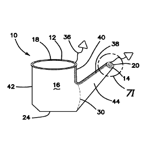
opening 14
of the bag 10 is sealed by various methods which will be described in greater
detail
below. For example, the sidewall 16 near the second opening 14 may be rolled-
up and
tucked or the sidewall 16 may be tied into a knot. With the second opening 14
sealed,
the entire bag 10 is removed through the vaginal canal. At the point of
removal, most of
the uterus or tissue specimen is already removed or reduced in size by the
morcellation
process.
[0099]
Turning now to FIG. 2, another containment bag 10 variation will
now be described using like numbers to designate like parts of the invention.
The bag
of FIG. 2 may also be used in any one or more of the methods described above.
The bag 10 includes a first opening 12, also called a mouth, and a second
opening 14
interconnected by a sidewall 16. A first ring 18 is provided at the first
opening 12 and a
second ring 20 is provided at the second opening 14. The rings 18, 20 are
connected to
the sidewall 16 by enclosing the rings 18, 20 in a pocket formed by the
sidewall 16 heat
sealed onto itself and/or with adhesive. The sidewall 16 is formed of any
suitable
flexible material including polymer, fabric, polymer reinforced with fabric,
mesh, nylon,
19
CA 02958574 2017-02-17
WO 2016/028789 PCT/US2015/045705
-
fibers and the like. The first opening 12 is larger than the second opening 14
and,
accordingly, the first ring 18 is larger than the second ring 20. The sidewall
16 forms a
funnel-like shape configuration dividing the lumen of the bag 10 into a first
compartment
26 and a second compartment 28. The first compartment 26 is substantially
parabolic,
funnel-like in shape having curved sidewalls when the bag 10 is in a natural
undeflected
orientation. The sidewall 16 is formed by heat-sealing the sidewall material
longitudinally forming one or more seams along the length of the bag 10. At
the
intersection of the first compartment 26 and second compartment 28, there is a
reduced
diameter location entryway 30 that advantageously reduces the amount of
specimen
passing therethrough and, as a result, creates a base 24 also called a bottom
or floor or
semi-floor for the bag 10 upon which a surgical tissue specimen may be
supported for
morcellation with the small entryway preventing tissue specimen from readily
moving
into the second compartment 28. The curved sidewall 16 helps retain the
specimen at
the base 24 forming a reservoir-like configuration. From the intersection 30
to the
second opening 14, the cross-sectional opening is substantially constant
and/or
gradually increases or decreases to create a tubular, sleeve-like section of
the bag 10
that is sized and configured for placement through the vaginal canal and that
is much
narrower than the first compartment 26 which has a larger cross-sectional
opening
along the first compartment 26. A first tether and tag may be attached to the
first ring
18 and a second tether and tag may be attached to the second ring 20 to
facilitate
placement of the bag 10 and to facilitate removal of the bag 10.
[0100] Turning now to FIGs. 3A-3C, there is shown another
containment
bag 10 according to the present invention. The containment bag 10 includes a
first
opening 12, also called a mouth, and a second opening 14 interconnected by a
sidewall
16. A first ring 18 is provided at the first opening 12 and a second ring 20
is provided at
the second opening 14. The rings 18, 20 are connected to the sidewall 16 by
enclosing
the rings 18, 20 in a pocket formed by the sidewall 16 heat sealed onto itself
and/or with
adhesive. The sidewall 16 is formed of any suitable sheet of flexible material
including
but not limited to polymer, polymer reinforced with fabric, mesh, nylon,
fibers and the
like. The first opening 12 is larger than the second opening 14 and the
sidewall 16
forms a frusto-conical configuration. Accordingly, the first ring 18 is larger
than the
second ring 20. The sidewall 16 is formed by heat-sealing the sidewall
material
CA 02958574 2017-02-17
WO 2016/028789 PCT/US2015/045705
-
longitudinally forming one or more seams along the length of the bag 10. The
bag 10
includes one or more inwardly extending lateral seams 32 reducing the lumen of
the
bag 10 at a location between the first opening 12 and the second opening 14.
The
seams 32 are formed into the sidewall 16 by selectively hot-sealing portions
of the
sidewall 16 together to reduce the diameter of the sidewall 16 in the location
of the
seam. Four seams 32 spaced around the sidewall 16 are shown in FIG. 3B and two
seams 32 are shown oppositely disposed in FIG. 3C. The seams 32 function to
reduce
the diameter of the bag 10 at a location anywhere including midway between the
two
openings 12, 14 and as a result creates a base 24 also called a bottom or
floor or semi-
floor for the bag 10 upon which a surgical tissue specimen may be supported.
In
general, the seams 32 function to close the sidewall 16 and create two
compartments in
the bag 10, a first proximal compartment 26 and a second distal compartment
28,
separated by the seams 32. At the intersection of the first compartment 26 and
second
compartment 28 there is a reduced entryway 30 that advantageously reduces the
amount of specimen passing therethrough and, as a result, creates a base 24 or
semi-
base. A first tether and tag may be attached to the first ring 18 and a second
tether and
tag may be attached to the second ring 20 to facilitate placement of the bag
10 and to
facilitate removal of the bag 10.
[0101] Turning now to FIG. 4, there is shown a containment bag 10
for the
purposes of showing the various dimensions of the bag 10 according to the
invention.
The dimensions are not limited to the exact configuration for the bag 10 but
approximately the same dimensions may be used for any one or more the bag
variations disclosed herein. The length A of the bag 10 is approximately 20.0
inches.
The diameter B at the first opening 12 is approximately 9.0 inches. The
diameter C at
the second opening 14 is approximately 5.0 inches. The distance D to the seams
32 or
fastener 22 from the second opening 14 is approximately 8.0 inches. The
diameter G of
the entryway 30 is approximately 1.5 inches. The rings 18, 20 are rigid,
resilient and
flexible and made of plastic capable of assuming a low-profile, compressed
configuration from a relaxed, normal, undeformed high-profile expanded
configuration.
The low-profile configuration is elongated and oval with the opening reduced
in side and
configured for easy insertion through a small incision. The high-profile
configuration is
substantially circular but may be of any shape. The rings 18, 20 are capable
of
21
CA 02958574 2017-02-17
WO 2016/028789 PCT/US2015/045705
-
supporting the bag sidewall 16 opening the bag sidewall 16 as the ring 18, 20
moves
from a low-profile configuration to a high profile configuration. The rings
18, 20 are
resilient and tend to spring back to their undeformed high-profile
configuration. A
clinician can easily compress the ring 18, 20 to reduce its size for insertion
through an
incision into a body cavity.
[0102] Turning now to FIGs. 5A-5B, there is shown another variation
of the
containment bag 10 wherein like reference numbers are used to describe like
parts.
The containment bag 10 includes a first opening 12, also called a mouth, and a
second
opening 14 interconnected by a sidewall 16. A first ring 18 is provided at the
first
opening 12 and a second ring 20 is provided at the second opening 14. The
rings 18,
20 are connected to the sidewall 16 by, for example, enclosing the rings 18,
20 in a
pocket formed by the sidewall 16 heat sealed onto itself and/or with adhesive.
The
sidewall 16 is formed of any suitable flexible material including fabric,
polymer, polymer
reinforced with fabric, mesh, nylon, fibers and the like. The first opening 12
is larger
than the second opening 14. Accordingly, the first ring 18 is larger than the
second ring
20. The sidewall 16 is formed by heat-sealing the sidewall material
longitudinally
forming one or more seams along the length of the bag 10. As shown in FIGs. 5A-
5B,
the bag 10 is formed into a first compartment 26 and a second compartment 28
with an
entryway 30 at their intersection. The first compartment 26 has a proximal
section that
is substantially cylindrical in shape with a vertical sidewall 16 connected to
a distal
section that is funnel-like in shape having an angled sidewall 16 when the bag
10 is in a
normal undeflected orientation as shown. The distal section that is funnel-
like in shape
is connected to the second compartment 28 via the entryway 30. The entryway 30
is
sized and configured to permit a scope to pass. A scope would be typically
inserted
through the second opening 14 into the second compartment 28 and extended all
the
way to near the entryway 30 for observation of morcellation taking place in
the first
compartment 26. Therefore, the entryway 30 is sized as small as possible to
prevent
escape of specimen from the first compartment 26 and to form a large enough
base 24
to support a specimen and large enough to receive the scope shaft. The angled
sidewall 16 of the funnel-like distal section of the first compartment 26
forms the base
24 also called a bottom or floor or semi-floor for the bag 10 upon which a
surgical tissue
specimen may be supported. The entryway 30 is as small as the diameter of a 5-
10mm
22
CA 02958574 2017-02-17
WO 2016/028789 PCT/US2015/045705
-
scope. In the variation shown in FIG. 5B, the diameter of the entryway 30 is
smaller
than the diameter of the second opening 14. The larger diameter at the second
opening
14 compared to the diameter at the entryway 30 facilitates the second ring 20
being
rolled upon itself to reduce the length of the second compartment 28. A third
ring (not
shown) may be further provided near the second ring 20 such that the second
ring 20
and the third ring serve as a built-in, integral retractor of the like
described above. The
larger second opening 14 relative to the diameter at the entryway 30 also
facilitates
insertion of instruments and retraction of tissue. The sidewall 16 of the
second
compartment 28 angles outwardly progressively with distance from the entryway
30 to
the second opening 20. The bag 10 of FIGs. 5A-5B is shown provided with a seal
mechanism 34 configured to seal the second opening 20 so that specimen does
not
spill from the bag 10. The various possible seal mechanisms 34 that can be
including in
this variation as well as in any variation of the containment bag 10 will be
described in
greater detail below. A first tether/tag 36 may be attached to the first ring
18 and a
second tether/tag 38 may be attached to the second ring 20 to facilitate
placement of
the bag 10 and to facilitate removal of the bag 10.
[0103] Turning now to FIGs. 7A-7R, there is shown a containment bag
10
according to the present invention. The containment bag 10 includes a first
opening 12,
also called a mouth, and a second opening 14 interconnected by a sidewall 16.
A first
ring 18 is provided at the first opening 12 and a second ring 20 is provided
at the
second opening 14. The rings 18, 20 are connected to the sidewall 16 by, for
example,
enclosing the rings 18, 20 in a pocket formed by the sidewall 16 heat sealed
onto itself
and/or with adhesive. The sidewall 16 is formed of any suitable flexible
material
including but not limited to fabric, polymer, polymer reinforced with fabric,
mesh, nylon,
fibers and the like. The first opening 12 is larger than the second opening
14. The
sidewall 16 forms a teapot shape wherein the second opening 14 forms the
opening at
the spout or neck of the vessel. The sidewall 16 includes a base 24 configured
for
supporting a tissue specimen. Unlike the previous variations described above
in which
the first opening 12 and second opening 14 were substantially coaxial or
otherwise
described as being in alignment with each other along a longitudinal axis of
the bag 10
when the bag 10 is laid flat or suspended in air in an undeflected
orientation, in this
variation, the first opening 12 and the second opening 14 are adjacent to each
other or
23
CA 02958574 2017-02-17
WO 2016/028789 PCT/US2015/045705
-
have longitudinal axes that are parallel or angled with respect to each other
wherein the
first ring 18 defines a first central longitudinal axis perpendicular to the
radial plane of
the ring 18 and/or opening 12 and the second ring 20 defines a second central
longitudinal axis perpendicular to the radial plane of the ring 18 and/or
opening 14. The
openings 12, 14 are eccentric or nonconcentric. The base 24 defines a first
side 40 and
a second side 42 relative to the base and first opening 12. The second opening
14 is
formed in the first side 40 of the bag 10. The first side 40 of the bag 10 may
form an
extension neck 44 of various sizes, shapes, lengths, and positional locations
with
respect to the side 40 and base 24. In FIG. 7A, the second opening 14 is
slightly lower
than the first opening 12 as measured from the base 24. In FIG. 7B, the second
opening 14 is at approximately the same height from the base 24 as the first
opening
12. In FIG. 7C, the second opening 14 is higher from the base 24 relative to
the first
opening 12 and also includes a narrower and longer neck extension 44 leading
to the
second opening 14 compared to a shorter neck extension 44 shown in FIGs. 7A,
7B
and 7D. In FIG. 7E, the neck extension 44 is positioned at the bottom of the
side 40
closer to the base 24. The angle of the neck extension 44 with respect to the
base 24 in
FIG. 7E is less than the angle of the neck extension 44 with respect to the
base 24 in
FIGs. 7A, 7B, 7C or 7D. In one such variation of FIG. 7E, one side of the neck
extension 44 is contiguous with the base 24 forming a larger effective base.
The angle
of the neck extension 44 is substantially equal to the base 24 and the neck
extension 44
is positioned a distance or height from the base 24. In FIG. 7F, the neck
extension 44 is
located in the middle of the side 40. In such a variation, the base 24 forms a
larger bowl
having wide sides for containing the specimen 16 and, advantageously,
preventing
movement of specimen into the neck extension 44. In FIG. 7G, the neck
extension is
located at the top of the side 40 near the first opening 12 and a greater
distance from
the base 24. Still referencing FIGs. 7A-7R, the size of the entryway 30 or
intersection
between with the neck extension 44 may vary. For example, in FIG. 7A, the
entryway is
larger than in FIG. 7B, similar to the difference in the entryway in FIGs. 7C
and 7D. In
FIG. 7F, the entryway 30 is very small and located between the first opening
12 and the
base 24 or substantially midway along the first side 40. In FIG. 7E, the
entryway 30 is
near and contiguous with the base 24. In FIG. 7G, the entryway 30 is near the
first
opening 12.
24
CA 02958574 2017-02-17
WO 2016/028789 PCT/US2015/045705
-
[0104] Turning now to FIGs. 7H-7P, the various tethers/tags and
their
various configurations will now be described. Each bag 10 includes at least
one of a
first tether 36 and an optional tag associated with the first opening 12 and a
second
tether 38 with an optional tag associated with the second opening 14. Some
figures in
this description show no tether, one tether at the first opening, one tether
at the second
opening, or a tether at both of the first and second openings; however, the
invention is
not so limited and any number of tethers and combinations are within the scope
of the
present invention, regardless of whether a figure shows such a combination of
various
tether locations and tether exclusions or inclusions. A tether can include a
string such
as one made of nylon, a tab, a film, a tape, a lead or the like. A tag is
attached to the
proximal end of the string. The tag is a piece of plastic that facilitates
locating and
grasping the tether. The tether may or may not include a tag. Furthermore, the
word
"tether" may be interchanged with the word "tab" and vice versa. In FIG. 7B, a
first tab
36 is shown at the second side 42 and a second tab 38 at the second opening
14. In
one variation, the first tab 36 is connected to the first ring 18 and the
second tab 38 is
connected to the second ring 20.
[0105] In FIG. 7H, a first tab 36 is interconnected with a second
tab 38
wherein the first tab 36 is located at the first opening 12 and exits at the
first side 40 and
the second tab 38 extends along the neck extension 44 and out at the second
opening
14. In FIG. 7H, the first tab 36 and the second tab 38 are the same tab, the
free ends of
which extend out from the bag 10 and include tags as shown and may or may not
be
attached fixedly to their respective rings 18, 20. In another variation, the
first tab 36 and
the second tab 38 are formed with separate tabs. The one or more tabs are
fixed
relative to the bag 10 and/or respective ring 18, 20. Of course, as mentioned
above, the
tabs may be tabs, strings, tethers, film, tape, lead and the like. FIG. 71
shows an
enlarged section of the second opening 14 of FIG. 7H, wherein the second tab
38 is
wrapped around the second ring 20 before exiting at the second opening 14. The
first
tab 36 may also be similarly wrapped around the first ring 18. In a variation
in which the
first tab 36 and the second tab 38 are separate tabs, the first tab 36 may be
connected
to the first ring 18 and not extend along the first side 40 of the bag 10. In
another
variation in which the first tab 36 and the second tab 38 are separate tabs,
the first tab
36 is fixed to the first ring 18 and or to the sidewall 16 and, if fixed to
the sidewall 16 it
CA 02958574 2017-02-17
WO 2016/028789 PCT/US2015/045705
-
may extend along the sidewall 16 by any distance. In one variation, the first
tab 36
extends along the first side 40 of the sidewall 16 to approximately near the
intersection
of the sidewall 16 and the neck extension 44. This configuration is
advantageous
because when the first tab 36 is pulled, the sidewall 16 portion that is above
the neck
extension 44 is pulled upwardly bringing the bag 10 closer to the abdominal
wall and will
scrunch together that portion of the sidewall 16 above the neck extension 44
making
removal of the bag 10 from the abdominal cavity easier. Also, the second tab
38 may
also extend along only a portion the neck extension 44. The neck extension 44
is a
distinct tubular, sleeve-like arm that branches from the main bag first
compartment 26
and extends laterally outwardly from the sidewall 16 in a straight or angled
orientation to
interconnect the second opening 14 with the first compartment 26 via an
intersection
called an entryway 30 that is located between the first opening 12 and the
second
opening 14.
[0106] In FIG. 7J, the bag 10 includes a first tab 36 at the second
side 42
exiting at the first opening 12 and a second tab 38 exiting the second opening
14. The
second tab 38 extends along the bottom of the neck extension 44 and runs
contiguously
along the base 24 as shown and may or may not interconnect with the first tab
36.
[0107] In FIG. 7K, the bag 10 includes a first tab 36 at the first
opening 12
and second side 42 adjacent and above the neck extension 44 and a second tab
38 at
the second opening 14. The second tab 38 extends along the length of the neck
extension 44 and upwardly along the first side 40 to the first opening 12 but
does not
exit at the first opening 12. Also, FIG. 7K illustrates a relatively large and
deep
specimen receiving portion in the lateral and vertical direction because the
base 24
extends contiguously into the neck extension 44 at the first side 40. The
first side 40 is
shown in FIG. 7K to extend from the first opening 12 approximately one third
of the
length of the first side 40 wherein the specimen receiving portion rises
approximately
two thirds upwardly from the base 24 along the length of the first side 40.
Having a
large specimen receiving portion which is the case in variations in which the
base 24 is
contiguous with the neck extension 44 prevents twisting of the neck extension
44
because the neck extension 44 is smaller at the second opening 14 compared to
the
width of the neck extension 44 at an entryway 30 formed by the intersection of
the neck
extension 44 with the first side 40. Therefore, the neck extension 44 flares
out or
26
CA 02958574 2017-02-17
WO 2016/028789 PCT/US2015/045705
-
widens in diameter with distance towards the bag 10 and decreases in size or
narrows
in diameter with distance towards the second opening 14. A scope that is
inserted in
through the second opening 14 can land the distal end of the scope near the
base 24 to
observe that careful morcellation is proceeding without compromise to the bag
walls.
Also, a zero degree scope may be employed easily to observe morcellation
taking place
inside the bag. Referring back to FIG. 7F, there is shown a neck extension 44
that has
approximately the same width or diameter at the second opening 14 as at the
entryway
30 formed by the intersection of the neck extension 44 with the first side 40.
The wider
entryway 30 advantageously provides a larger specimen viewing and receiving
location
and also minimizes twisting of the neck extension 44 about itself.
[0108] Turning now to FIGs. 7L and 7M, the configuration of the tab
with
respect to the bag 10 will be described in greater detail wherein the neck
extension 44
is shown for illustrative purposes and the same configuration may be applied
to
anywhere in the bag 10 where a tab is located including the sidewall 16, first
side 40,
and second side 42. The sidewall 16 will have a primary seam 46a, 46b formed
along
the edges of the bag. The primary seam 46a, 46b is formed by adhesive and/or
hot
sealing two sides of the bag sidewall 16 together. The primary seam 46a, 46b
helps
define the shape of the bag 10. A secondary seam 48 is shown adjacent to a
primary
seam 46a and spaced apart from the primary seam 46a to form a channel 50 for
the tab
36, 38. Of course, in some areas of the bag 10, there may be no primary seam
46a,
46b, in which case, the secondary seam 48 is formed near the edge of the
sidewall 16.
The tab 36, 38 may be fixed within the channel 50 or may be free to translate
within the
channel 50. FIG. 7M illustrates the axis of the tab 38 which defines an axis
of rotation
about which the neck extension 44 would tend to rotate. The presence of a tab
38 at
the neck extension 44 advantageously permits a rotated or twisted neck
extension 20 to
be quickly straightened by simply pulling the tether 38 at the proximal end
where the tag
is located. The tab 38 may be at anywhere around the neck extension 44. In one
variation, the tab 38 is along at least a portion of top of the neck extension
44. This
configuration advantageously permits the second tab 38 to be lifted by raising
the tag at
the end of the tab 38 and allowing the weight of the remainder of the neck
extension 44
that is wrapped or tangled about itself along and around the longitudinal axis
of the neck
extension 44 to unfurl and unflip in a relatively downwardly direction to open
the lumen
27
CA 02958574 2017-02-17
WO 2016/028789 PCT/US2015/045705
-
of the neck extension 44. The unfurling or untangling of the neck extension 44
is
preferably performed while the neck extension 44 is inside an insufflated
patient cavity
and before the second ring 20 is pulled into a position such as through an
incision or
body orifice such as the vagina. After the second ring 14 is resident outside
the patient,
untwisting the neck extension 44 becomes more difficult due to pressure from
the
adjacent tissue margin onto the neck extension 44. The tab 38 along at least a
portion
of the neck extension 44 greatly assists in quickly orienting and positioning
the neck
extension relative to the anatomy. Pulling or lifting the tab 38 untwists the
neck
extension 44 and prevents it from interfering with the scope when it is
inserted and also
when the scope is viewing specimen. The tab 36, 38 may be contrast colored
against
the rest of the bag sidewall so that the user can view the tab 36, 38 to
discern if the
position of the neck extension 44 is correct. For example, a user will see the
colored
tab 36, 38 and if it is oriented along a bottom end of the neck extension 44
or does not
form a straight line, for example, the user will know that there is one or
more twists in
the neck extension 44 and that the tab 36, 38 needs to be pulled such that the
tab 36,
38 is a straight line along the top of the neck extension 44. In lieu, of a
tab 36, 38
serving as an indicator for the proper orientation of the bag 10, the bag 10
itself may be
printed with indicator markers such as lines and arrows in contrast color to
provide
information to the user about the position of the bag 10 and/or neck extension
44.
[0109] In another variation, and with reference to FIGs. 24A, the
channel
50 along the neck extension 44 can be connected to a source of insufflation
fluid, which
when delivered into the channel 50, unfurls the neck extension 44 into the
proper
orientation and direction. The channel 50 may extend only along the neck
extension 44
or along the sidewall 16 of the bag 10. In FIG. 24A, the channel 50 is shown
to extend
along both the neck extension 44 and sidewall 16 to the first opening 12 from
the
second opening 14. The proximal end of the channel 50 can have a connector 124
configured for connection to the source of insufflation fluid and resident
outside the
patient, for example near the first opening 12 as shown in FIG. 24B or near
the second
opening 14 as shown in FIG. 24A. In both FIG. 24A and FIG. 24B, the channel 50
extends from the first opening 12 to the second opening 14. The channel 50 can
be
applied for any variation of bag 10 described herein and is not limited to the
sleeve-like
and two-headed bags as shown in FIGs. 24A and 25B. One or more channels 50 may
28
CA 02958574 2017-02-17
WO 2016/028789
PCT/US2015/045705
-
be provided that are interconnected or separated. The channels 50 are shown to
be
straight but may also form a pattern suitable for insufflation or include a
plurality of
spaced apart rings around the neck extension 44 or other part of the bag 10.
The
channel 50 is formed by heat sealing a portion of the bag together, as
described above,
to form a primary seam 46 and a secondary seam 48 as shown in FIG. 24C. The
channel 50 may also be a separate tube attached internally or externally to
the bag 10.
[0110] In
another variation, a connector 124 is provided at the proximal
end of the bag at or near the first opening 12 that is configured to perform
one or more
of the following functions: insufflating the bag 10, insufflating a second bag
10,
insufflating an inner bag, insufflating an outer bag, insufflating the
abdominal cavity, and
insufflating the channel 50. For example, as shown in FIG. 25, a Y-shaped
connector
124 connected to a source of insufflation fluid can divert insufflation fluid
into the interior
of the bag 10 and into the abdominal cavity 74 outside the bag 10 via a trocar
90 or
insufflation needle. An optional access port cap/platform 76 may be used to
seal the
first opening 12 and the connector 124 may be connected to the cap/platform 76
or to
the bag 10 itself. Insufflation of both the bag 10 and abdominal cavity 74
creates an
equal pressure. The bag 10 acts as a membrane and the organs in the abdominal
cavity are advantageously moved away from the bag 10, thereby, protecting the
organs
from inadvertent morcellation. In another example, the connector 124 can be a
three-
way connector to direct insufflation fluid into the abdominal cavity 74, into
the bag 10
and into the channel 50 to unfurl the neck extension 44. Another variation is
shown in
FIG. 26 in which the system includes a first bag 10 containing the specimen 78
and a
second bag 11 that contains the first bag 10. The first bag 10 or inner bag 10
is located
inside the second bag 11 or outer bag 11. A connector 124 is configured to
deliver
insufflation fluid to one or more of the first bag 10 and second bag 11.
Preferably, both
the first bag 10 and the second bag 11 are insufflated via the connector 124.
An access
port cap/platform 76 is provided to seal insufflation pressure within the
first bag 10 and
the connector 124 may be connected directly to the each bag 10, 11 or via the
cap/platform 76 for delivery of insufflation fluid to the first bag 10 and
directly to the
second bag 11 for delivery of insufflation fluid to the second bag 11. The
connector 124
in FIG. 126 may be a three-way connector 124 and further deliver insufflation
fluid into
the abdominal cavity 74. The double-bag system of FIG. 26 advantageously
provides
29
CA 02958574 2017-02-17
WO 2016/028789 PCT/US2015/045705
-
added protection in the event the inner bag 10 is accidentally punctured with
surgical
instruments. In such an event, containment of the specimen would not be
breached as
the outer bag 11 would retain the specimen in a closed system.
[0111] Turning now to FIGs. 7N-7P, there is shown more detail of
the
tether/tab configuration at either the first opening 12 or the second opening
14 or both.
For illustrative purposes, the second opening 14 and a section of the neck
extension 44
is shown in FIG. 7N. The tab 38 extends inside a channel 50 and exits at the
second
opening 14. Placement of the tab 38 inside the channel 50 is for exemplary
purposes
and the tab may be integrally formed with the bag. In FIG. 70, the detail of
the second
ring 20 is shown for illustrative purposes and the same configuration may be
applied to
the first ring 18 at the first opening 12. In FIG. 70, the tether 38 is tied
or wrapped
around the second ring 20. A knot may also be formed. In FIG. 7P, the tether
38 is
looped around the second ring 20 multiple times forming multiple windings
before
exiting at the second opening 14. A knot may also be formed in the variation
of FIG. 7P
to secure the tether 38 to the second ring 20. The tether may be attached
anywhere
along the ring and/or bag and the same may be applied to the first opening 12.
FIG. 70
illustrates the bag 10 of FIGs. 7A-7R in use which will be described in
greater detail
below. FIG. 7R illustrates a containment bag 10 as described herein according
to the
present invention.
[0112] Turning now to FIG. 8A, the seal mechanism 34 applicable to
the
neck extension 44 or second compartment 28 will be described in greater
detail. The
seal mechanism 34 is configured to seal off the second opening 14 of any bag
variation
shown herein. When the morcellation is completed and the bag 10 is ready for
removal,
it will be removed from either an incision in the abdominal wall such as at
the umbilicus
or it will be removed through the vaginal opening or other orifice. As such,
the bag 10
will be pulled out at one end; hence, the opposite end must be sealed off to
maintain a
closed system and prevent specimen from spilling out. The seal mechanism 34
will be
described with respect to the second opening 14 as that is preferred location
for the
seal mechanism 34. The seal mechanism 34 includes a first pocket 52 and a
second
pocket 54. The first pocket 52 is located on one side of the bag 10 and the
second
pocket 54 is generally located on the opposite side of the bag 10; however,
the
invention is not so limited. The first pocket 52 is formed by attaching a
first patch 56 to
CA 02958574 2017-02-17
WO 2016/028789 PCT/US2015/045705
-
the outer surface of the sidewall 16. The first patch 56 is attached with
adhesive or by
heat sealing the first patch 56 to the sidewall 16. In one variation, the
first patch 52 is
attached along three sides of its perimeter leaving one side of the perimeter
detached
and serving as part of the mouth to the first pocket 52. The first patch 52 is
shown with
cross hatch marks in FIG. 8A. The second pocket 54 is formed by attaching a
second
patch 58 to the outer surface of the sidewall 16 on the opposite side of the
first patch
56. The second patch 58 is attached with adhesive or by heat sealing the
second patch
58 to the sidewall 16. In one variation, the second patch 58 is attached along
three
sides of its perimeter leaving one side of the perimeter detached and serving
as part of
the mouth to the second pocket 54. The second patch 58 is shown with dashed
hatch
marks in FIG. 8A. The mouth 60 of the first pocket 52 faces distally away from
the
second opening 14 and the mouth 62 of the second pocket 54 faces proximally
toward
the second opening 14. Therefore, the pocket openings 60, 62 face each other.
Also,
the pocket openings 60, 62 are aligned longitudinally along the with the
second opening
14 such that the first pocket 52 is distally located from the second opening
14 and the
second pocket 54 is distally located from the first pocket 52.
[0113] In use and with reference to FIGs. 8B-8E, the resilient
second ring
20 is squeezed into a low-profile configuration as shown in FIG. 8B. The
second ring 20
is rolled distally such that the sidewall 16 of the neck extension 44 is
rolled onto the
second ring 20 all the way over the first pocket 52 to the distally facing
first mouth 60 as
shown in FIG. 8C. The rolled up neck extension 44 is inserted into the first
pocket 52 as
shown in FIG. 8D. Then the first pocket 52 with contents is folded over
towards the
back side and the first pocket 52 is inserted/tucked into the second pocket 54
as shown
in FIG. 8E. The first pocket 52 is inserted into the second pocket 54 such
that the
second pocket 54 encompasses the first pocket 52 and its contents. The tucking
of the
first pocket 52 into the second pocket 54 advantageously prevents the rolled
bag from
snagging onto anything during post morcellation bag retrieval. This
configuration of the
bag 10 and method advantageously seals the contents including fluids inside
the bag 10
and prevents them from escaping through the second opening 14 during bag 10
removal. The resilient second ring 20 when squeezed is biased to expand to its
enlarged high-profile configuration. Advantageously, such resiliency of the
second ring
20 biases the second ring 20 together with the sidewall 16 rolled onto it
towards the
31
CA 02958574 2017-02-17
WO 2016/028789 PCT/US2015/045705
-
inside walls of the first pocket 52. The resiliency of the second ring 20
creates a locking
feature and sealing effect as the second ring 20 tends outwardly and pushes
portions of
the sidewall 16 against adjacent portions of the rolled-up sidewall 16. Hence,
rolling of
the bag 10 and the resilient second ring 20 creates a seal.
[0114] Other constructions and methods for sealing the second
opening
20 will now be described. Turning now to FIG. 9, there is shown another method
for
sealing the second opening 14 of the containment bag 10 in which a knot 64 is
tied at
the distal end. In another variation, the distal end of the bag 10 is provided
with double-
sided tape 66 which seals the second opening 14 at a distance proximal to the
second
ring 20 as shown in FIG. 10. Turning to FIG. 11, an interlocking ridge and
groove 68 is
provided in which the groove is formed on one inner surface of the sidewall 16
and the
ridge is formed on an opposite inner surface of the sidewall 16. The ridge is
configured
to interlock with the groove when pressed together by a user's fingers or by
employing a
zipper. In FIG. 12, a seal 70 is created by employing a bipolar instrument 72
to deliver
electrical current or heat to heat seal or melt the opposite sidewalls 16 at
the neck
extension 44 together to seal the bag 10. In such a variation, the bag 10 is
made of
suitable material such as thermoplastic and the instrument 72 is set so as to
not burn or
melt the bag 10 too much.
[0115] In use, after the uterus has been detached as described
above, the
insertion and removal of a containment bag 10 of the like described with
respect to
FIGs. 7-12 will now be described. Aspects of this method may also apply to any
bag
variation described herein. The containment bags 10 of FIGs. 7A-7R will be
referred to
as dual-head bags 10 for ease of reference and to differentiate from the tube-
like bags
of FIGs. 1-6. Firstly, any trocar is removed from the umbilical incision. Any
one of the
dual-head bags 10 of FIGs. 7A-7R is inserted through the umbilical incision
and the
trocar is re-inserted. The trocar may be inserted directly into the umbilical
incision or
through an access port cap/platform connected to a retractor placed in the
incision.
Referring back to FIG. 70, the abdominal cavity is re-insufflated via the
access port
cap/platform 76 or through the trocar in order to provide a better view for
positioning the
bag 10. A scope is inserted through the umbilical incision 80 and the detached
uterus
78 is inserted into the bag 10 with graspers. A second incision 82 is made
through the
abdominal body wall 84 in a location medial-to-lateral of the umbilicus. A
surgical
32
CA 02958574 2017-02-17
WO 2016/028789 PCT/US2015/045705
-
grasper is inserted through the second incision 82 and the tether at the
second opening
14 is grasped and pulled through the second incision 82 pulling the neck
extension 44
towards the abdominal body wall 84. The smaller second ring 20 is pulled
through the
second incision 82. In one variation, if the neck extension 44 is sufficiently
long, the
second ring 20 can be pulled through the vaginal canal and opening. The tether
attached to the larger first ring 18 is pulled toward the umbilical incision.
As the first
opening 12 of the bag 10 is drawn towards the abdominal body wall 84, the
trocar
and/or the access port cap/platform 76 are removed and the first ring 18 and a
proximal
portion of the bag 10 is pulled through the umbilical incision. If a retractor
86 is in
position at the umbilical incision, the retractor 86 may be removed before the
first ring
18 is pulled through. If the retractor 86 is removed, the first ring 18 is
brought to the
surface of the abdominal body wall 84 and the retractor 86 is inserted into
the first
opening 12 of the bag 10. The adjacent tissue and the bag 10 in the location
of the
umbilical incision 80 is retracted with the retractor 86 as shown in FIG. 70.
The access
port cap/platform 76 is then connected to the retractor 86 by snapping the
access port
cap/platform 76 under or over the first ring of the retractor 86. The bag 10
is held firmly
in place between the retractor 86 and tissue wall 84 at the umbilical
incision. If the
retractor 86 is not removed, the bag 10 is pulled through the lumen of the
retractor 86
and laid over the first ring of the retractor outside the abdominal wall. The
access port
cap/platform 76 is re-attached by snapping the access port cap/platform 76
either
under/over the first ring 18 of the bag 10 or the first ring of the retractor
86. If the
access port cap/platform 76 is snapped under/over the first ring of the
retractor 86, the
bag sidewall 16 will be captured between the retractor 86 and the access port
cap/platform 76 holding it in position. If the retractor 86 is not be used at
all, in which
case, the bag 10 is inserted into the umbilical incision 80 or if a retractor
86 is used
initially to insert the dual-head bag 10, it may not be re-inserted into the
bag 10 at the
first opening 12 as described above. In such a situation, the first ring 18 of
the bag 10 is
pulled through the umbilical incision 80 and overlaid onto the abdominal body
wall 84.
The access port cap/platform 76 is attached directly to the first ring 18 of
the dual-head
bag 10. A morcellator is inserted into the dual-head bag 10 through the first
opening 12
and a scope 88 is inserted through the second opening 14 and into the neck
extension
44 towards the entryway 30 to the first compartment 26. The scope 88 may be
inserted
33
CA 02958574 2017-02-17
WO 2016/028789 PCT/US2015/045705
-
directly into the dual-head bag 10 or through a trocar 90 placed inside the
second
opening 14 as shown in FIG. 70. FIG. 20 also illustrates in greater detail a
trocar 90
inserted into the second opening 14 of the bag 10. The bag 10 is pulled
through an
incision that is small enough to fit a trocar 90 such that the bag sidewall 16
is sealed
against the tissue margin 45 by the trocar 90 so that insufflation gas does
not escape
from the abdominal cavity 74 as shown in FIG. 20. FIG. 23 illustrates a trocar
90
configured to be removably and sealingly attached at the second opening 14. In
FIG.
23, an attachment feature at the end of the neck extension 44 sealingly snaps
and locks
onto the trocar 90 to maintain a pressure and prevent insufflation fluid from
escaping
from inside the bag 10 or inside the abdominal cavity 74. Alternatively, as
shown in
FIG. 21, at least a proximal portion of the neck extension 44 along with the
second ring
20, if one is employed, is pulled through the cannula lumen of the trocar 90.
In this
manner, a seal against the tissue margin 45 is provided by the trocar 90 being
inserted
into an incision that is equally sized or smaller than the outer diameter of
the trocar 90
to prevent the escape of insufflation gases inside the abdominal cavity 74. In
one
variation, the trocar 90 is provided with a balloon 92 which retracts the
tissue along with
the sidewall 16 of the bag 10 located in the second incision 82.
Alternatively, an access
port cap/platform may be attached to the second ring 20 and the scope 88
inserted
through the access port cap/platform with or without a trocar 90. In another
variation, at
least one seal 120 is provided at the second opening 14 as shown in FIG. 22.
The seal
120 may be removably fitted with the second opening such as in a snap-fit or
twist-and-
lock configuration. More than one seal can also be provided in a seal assembly
fitted
and connected the second opening 14. The seal assembly may include a zero seal
that
prevents escape of gas and fluid across the seal when no instrument is
inserted through
the zero seal. The zero seal may be a double duckbill type valve or other
valve. The
seal assembly may further include an instrument seal that seals against an
inserted
instrument to prevent escape of fluid and gas across the seal. Also, a seal
shield may
be provided to protect the seal from being damaged due to impingement with an
instrument. The morcellation of the uterus 78 is commenced while under
unobstructed
observation via the scope 88. After morcellation is completed, the
morcellator, the
scope 88 and trocar 90 (if used) are removed from the second opening 14. The
neck
extension 44 is sealed by closing the second opening 14 according to any one
of the
34
CA 02958574 2017-02-17
WO 2016/028789 PCT/US2015/045705
-
methods described above to prevent any particles of specimen or fluid
remaining inside
the bag from escaping the bag 10 during the removal of the bag 10 from the
patient.
The second ring 20 of the bag 10 is inserted into the abdominal cavity 74
through the
second incision 82. In one variation, the neck extension 44 is rolled up and
tucked into
the first and second pockets 52, 54 or, alternatively, the neck extension 44
is tied into a
knot 64. Any access port cap/platform 76 and/or retractor 86 at the umbilical
incision 80
are removed and the dual-head bag 10 is removed out of the body cavity 74
through the
umbilical incision 80. This same procedure may be employed for the tube-like
bags 10
throughout the specification such as those shown in FIGs. 1-6. The containment
bag 10
and methods effectively create a contained morcellation system wherein
morcellation,
either manual or power, is carried out inside a closed system provided by the
containment bag 10 and its placement within the anatomy. The openings to the
bag 10
are sealed and the procedure carefully performed to prevent inadvertent
scattering of
tissue throughout the abdominal cavity. The containment bag 10 advantageously
also
provides a portal into the bag via the neck extension or second opening
through which a
scope can be inserted to further monitor the morcellation procedure making
sure that
the bag integrity is not broken during the process. This provides to the
surgeon an extra
safety precaution with direct observation of the surgical morcellation field
while
maintaining a closed system. The angle of observation via the neck extension
or
second opening provides the viewer a clear and lateral view of both the bag
and the
specimen and their position with respect to morcellation instruments
throughout the
morcellation. Also, the systems and variations of the present invention
provide an easy
way to deploy the bag internally into position.
[0116] After a uterus is detached laparoscopically, a bag 10 is
inserted into
the abdominal cavity 74 either vaginally or abdominally. At the point of bag
insertion,
pneumoperitoneum may be lost. After the bag is inserted, pneumoperitoneum is
re-
established. The detached uterus is placed inside the bag 10 and the bag 10 is
laparoscopically manipulated to pull the bag openings through the desired
locations
which may include any one or more of the following locations: umbilicus
incision,
abdominal incision, lateral incision and vaginal opening. The tether/tab is
pulled and a
trocar is placed into the second opening 14 or the second opening 14 is capped
with an
access platform or port or the second opening 14 is pulled through the lumen
of the
CA 02958574 2017-02-17
WO 2016/028789 PCT/US2015/045705
-
trocar 90. All the bag openings are then closed and sealed and insufflation is
introduced into the bag and/or abdominal cavity. The specimen inside the bag
is then
morcellated. Morcellation may be carried out using power or manual
morcellation
methods and instruments. The second opening 14 and other bag port openings are
sealed off except for one opening, such as the first opening 12, that will be
pulled to
remove the bag such as through the incision at the umbilicus. The bag port
openings
are sealed to prevent any specimen from escaping containment inside the bag 10
as
the bag is being removed. The bag is removed by being pulled through the
abdominal
incision such as an incision at the umbilicus. Additional variations of the
invention will
now be described for which the methods and features described above can be
applied
in whole or in part to the variations that follow and vice versa.
[0117] Turning now to FIG. 13, there is shown a containment bag 10
according to the present invention wherein like parts are referenced with like
numerals.
The containment bag 10 includes a first opening 12, also called a mouth, and a
second
opening 14 interconnected by a sidewall 16. A first ring 18 is provided at the
first
opening 12 and a second ring 20 is provided at the second opening 14. The
first ring 18
and the second ring 20 have substantially the same diameters. The rings 18, 20
are
resilient and capable of deflection into a low-profile configuration for
insertion through
ports/incisions having diameters that smaller than the rings 18, 20. The
sidewall 16 of
the bag 10 has a substantially cylindrical tube-like shape having a constant
diameter
that is substantially the same diameter as the rings 18, 20. The sidewall 16
defines a
central lumen that can also be called a first compartment 26 between the first
opening
12 and the second opening 14. The bag 10 of FIG. 13 is bi-directional compared
to the
bag 10, for example, of FIG. 1A wherein the smaller second opening 14 seats
more
readily within and at the vaginal opening or other orifice than a bag with a
larger second
opening 14. However, if any one of the openings 12, 14 is too small it will be
difficult to
insert the specimen into the bag 10.
[0118] Turning now to FIGs. 14A-14C, a method of using a
containment
bag 10 according to the present invention will be described. In one variation,
a tube-like
sleeve bag 10 such as shown in FIGs. 1-6 and 13 is provided. A tissue specimen
78,
such as a uterus, is detached and the bag 10 is inserted through an abdominal
incision
or orifice into a body cavity. The bag 10 is placed such that the first ring
18 is resident
36
CA 02958574 2017-02-17
WO 2016/028789 PCT/US2015/045705
-
outside the patient at the location of the abdomen or orifice. A surgical
instrument 94,
such as surgical graspers, is inserted into the first opening 12 of the bag 10
and into the
lumen of the bag 10. The specimen 78 is grabbed and pulled through the second
opening 14 of the bag 10 into the lumen of the bag 10 as shown in FIG. 14A.
The
proximal end of the instrument 94 is manipulated outside the patient to open
and close
the jaws of the grasper at the distal end of the instrument. The specimen 78
is released
inside the lumen compartment 26 as shown in FIG. 14B. The instrument 94 is
then
moved distally past the specimen 78 to grab the second ring 20 of the bag 10.
The
second ring 20 is grasped by the graspers 94 and pulled proximally into the
lumen
compartment 26 as shown in FIG. 14B. The second ring 20 is pulled along inside
the
lumen of the bag 26 proximally past the specimen 78 as shown in FIG. 14C and
to the
surface outside the patient creating a fold in the sidewall 16 inwardly into
the lumen of
the bag 10. After being pulled outside the patient, the second ring 20 can
then be
placed to the side of the first ring 18. The one or more fold divides the bag
10 and
creates within the bag 10 a first pouch 96 that contains the specimen 78 and a
second
pouch 98 adjacent to the first pouch 96. The bag 10 is invaginated, inverted,
turned or,
otherwise, folded back into itself up the lumen toward the first ring 18 to
form the
pockets 96, 98. This action also advantageously pulls the specimen 78 closer
to the
first ring 18 where the specimen 78 can be more readily visualized and
morcellated. To
assist the morcellation, a scope (not shown) may be inserted into the second
pouch 98
to observe the specimen 78 located in the first pouch 96 across the sidewall
16.
Alternatively, a scope is inserted into the second opening 14 of the bag 10
and into the
abdominal cavity and the specimen 78 is observed outside the first pouch 96.
In
another variation of the method, after the uterus is detached, the bag 10 may
be
inserted through the vaginal opening and the bag 10 positioned such that the
first ring
18 is located outside the patient at the vagina. This method and bag 10 can be
employed with any specimen, orifice or incision and is not limited to the
uterus, vaginal
opening and abdominal incision. Of course, the bag can be placed into any
incision or
orifice and pulled from any incision or orifice including the same incision or
secondary
incision.
[0119] Turning now to FIG. 15 there is shown a containment bag 10
according to the present invention wherein like parts are referenced with like
numerals.
37
CA 02958574 2017-02-17
WO 2016/028789 PCT/US2015/045705
-
The containment bag 10 includes a first opening 12, also called a mouth, and a
second
opening 14 interconnected by a sidewall 16. A first ring 18 is provided at the
first
opening 12 and a second ring 20 is provided at the second opening 14. Either
one or
more of the first end and the second end of the bag 10 includes a third ring
100 located
near the first ring 18 or the second ring 20, respectively. For example, in
FIG. 15, a
third ring 100 is located near the second end of the bag 10 near the second
ring 20.
The second ring 20 is located at the distal second end of the bag 10 and the
third ring
100 is spaced proximally from the distal second end by a distance configured
for
retraction purposes. Together with the second ring 20, the third ring 100
forms a
retractor built-in with the bag 10. When positioned within the anatomy as
described
above, the second ring 20 will reside outside the patient such as outside the
vaginal
opening while the third ring 100 will reside inside the patient. The second
ring 20 is
resilient and capable of being flipped about itself to wrap the intermediate
sidewall
located between the second ring 20 and the third ring 100 around the second
ring 20,
thereby, retracting a tissue margin at the orifice, or incision to facilitate
removal of a
specimen placed inside the bag 10. The bag 10 of FIG. 15 is shown to have a
frusto-
conical shape; however, the employment of a third ring 100 is not limited to a
bag 10
having this shape and can be used in any of the bag 10 variations described
herein
including the two-headed variations. Of course, in an alternate variation, the
third ring
100 may be position near the first ring 18 and configured to serve the same
built in
retraction function. In another variation, a fourth ring (not shown) is
provided adjacent
to the first ring 18 and a third ring 100 is located near the second ring 20
such that
retraction of tissue can take place at both ends of the bag 10.
[0120] Turning now to FIG. 16, there is shown another containment
bag 10
variation according to the present invention wherein like reference numbers
are used to
describe like parts. The bag 10 of FIG. 16 is similar to the teapot-like
containment bag
configurations of FIGs. 7A-7R having a neck extension 44. The bag 10 includes
a first
opening 12 and a second opening 14 interconnected by a sidewall 16. A first
ring 18 is
provided at the first opening 12 and a second ring 20 is provided at the
second opening
14. The bag 10 further includes a third opening 102 and a third ring 104 at
the third
opening 102. The sidewall 16 includes a base 24 configured for supporting a
tissue
specimen. The first opening 12, second opening 14 and third opening 102 are
adjacent
38
CA 02958574 2017-02-17
WO 2016/028789 PCT/US2015/045705
-
to each other or have longitudinal axes that are angled with respect to each
other
wherein the first ring 18 defines a first central longitudinal axis
perpendicular to the
radial plane of the ring 18 and/or opening 12, the second ring 20 defines a
second
central longitudinal axis perpendicular to the radial plane of the ring 18
and/or opening
14 and the third ring 104 defines a third central longitudinal axis
perpendicular to the
radial plane of the ring 104 and/or opening 102. The openings 12, 14, 104 are
eccentric. The base 24 defines a first side 40 and a second side 42 relative
to the base
24 and first opening 12. The second opening 14 is formed in the first side 40
of the bag
and the third opening 102 is formed in the second side of the bag 10. The
first side
40 of the bag 10 may form an extension neck 44 of various sizes, shapes,
lengths, and
positional locations with respect to the side 40 and base 24 interconnecting
the first
opening 12 with the second opening 14 and the second side 42 of the bag 10 may
form
a neck extension 106 of various sizes, shapes, lengths and positional
locations with
respect to the side 42 and base 24 interconnecting the first opening 12 with
the third
opening 102 and, of course, to the interior of the bag 10. In use, the bag 10
of FIG. 16
is positioned with respect to the anatomy such that the first opening 12 is at
the
abdomen such as inserted through an umbilical incision and resident with the
first ring
18 outside the patient. The second opening 14 serves as a lateral port
positioned at a
lateral incision in the abdomen or at a lateral orifice such as the vagina
with the second
opening 14 and second ring 20 residing outside the patient. The third opening
102 also
serves as a lateral port positioned at a lateral incision in the abdomen.
[0121] FIG. 17 illustrates yet another variation of the bag 10
further having
a fourth opening 108 and a fourth ring 110 located at the fourth opening 108.
The fourth
opening 108 defines a fourth central longitudinal axis perpendicular to the
radial plane
of the ring 110 and/or opening 108. The fourth longitudinal axis may or may
not be
parallel to the first longitudinal axis associated with the first opening. The
fourth
opening 108 is substantially coaxial with the first opening 12 making the bag
10 of FIG.
17 a hybrid bag that combines the teapot-like bags of FIGs. 7A-7R and the
sleeve-like
bags of FIGs. 1-6, 13 and 15. The fourth opening 108 is formed in the base 24
of the
bag 10 and the base 24 may form an extension neck 112 of various sizes,
shapes,
lengths, and positional locations with respect to the base 40 and base 24
interconnecting the first opening 12 with the fourth opening 108. In use, the
bag 10 of
39
CA 02958574 2017-02-17
WO 2016/028789 PCT/US2015/045705
-
FIG. 17 is positioned with respect to the anatomy such that the first opening
12 is at the
abdomen such as inserted through an umbilical incision and resident with the
first ring
18 outside the patient. The second opening 14 serves as a lateral port
positioned at a
lateral incision in the abdomen with the second opening 14 and second ring 20
residing
outside the patient. The third opening 102 also serves as a lateral port
positioned at a
lateral incision in the abdomen and the fourth opening 108 is position at a
lateral orifice
such as the vagina.
[0122] Turning now to FIGs. 18A and 18B, there is shown a
containment
bag 10 having at least a first opening 12 and sidewall 16 defining at least an
interior first
compartment 26 accessible via at least the first opening 12. A resilient first
ring 18 is
provided at the first opening 12. The bag 10 includes at least one window 114
of clear,
transparent glass or plastic through which visualization of the contents of
the
compartment 26 is possible from outside the bag 10 via a scope 88. The window
114
may include a lens that provides an improved visualization when a scope 88 is
placed
next to the lens as shown in FIG. 18B. The window 114 and/or lens may be flush
with
the exterior sidewall 16 of the bag 10 or recessed at the end of an inwardly
extending
port 116 as shown in FIG. 18B. The port 116 is cylindrical and sized slightly
larger than
the distal end of the scope 88. The inwardly extending port 116 provides a
closer
visualization of the bag contents and also provides a resting ledge for the
scope 88.
[0123] Turning now to FIGs. 19A and 19B, there is shown a
containment
bag 10 having at least a first opening 12 and sidewall 16 defining at least an
interior first
compartment 26 accessible via at least the first opening 12. A resilient first
ring 18 is
provided at the first opening 12. The bag 10 includes at least one port 118 in
the
sidewall 16 providing access to the interior compartment 26. The port 118 is
fitted with
at least one seal 120. More than one seal can also be provided in a seal
assembly
fitted and connected to the port 118. The seal assembly may include a zero
seal that
prevents escape of gas and fluid across the seal when no instrument is
inserted through
the zero seal. The zero seal may be a double duckbill type valve or other
valve. The
seal assembly may further include an instrument seal that seals against an
inserted
instrument to prevent escape of fluid and gas across the seal. Also, a seal
shield may
be provided to protect the seal from impingement with an instrument.
Surrounding the
seal 120 and port 118 may be a circumferential reinforcement 122 of plastic
having a
CA 02958574 2017-02-17
WO 2016/028789 PCT/US2015/045705
-
disk-like or funnel-like shape. The reinforcement 122 is made of stiffer
plastic relative to
the sidewall 16 of the bag 10. The reinforcement 122 provides a smooth funnel
shaped
entry to guide an instrument in through the seal 120 and port 118. Also, the
reinforcement 122 provides a platform for connecting the seal 120 or seal
assembly to
the bag 10. As shown in FIG. 19B, an instrument, such as a scope 88, is
inserted in
through the port 118 to perform surgical procedures inside the bag 10 or to
observe a
specimen undergoing morcellation inside the bag. The seal 120 on the bag 10
will
maintain any pressure differential across the bag 10 sidewall if, for example,
the
abdomen and/or bag 10 are insufflated.
[0124] Turning now to FIGs. 27-29, there is shown a containment bag
10
according to the present invention with different means for retaining the neck
extension
44 in a retracted configuration to facilitate insertion of the bag 10 into the
abdominal
cavity. In FIG. 27, a perforation 126 is provided in the sidewall 16 at a
location between
the neck extension 44 and a first side of the bag 10. The perforation 126
extends
downwardly such that the first opening 12 of the bag 10 remains interconnected
to the
second opening 14. The perforation 126 is configured such that integrity of
the bag is
not compromised by providing a reinforcement that prevents further
perforation. The
bag 10 is delivered into the abdominal cavity and then the perforation 126 is
perforated
inside the abdominal cavity with a surgical instrument or by pulling a
tab/tether 38 at the
second opening or a tab/tether located along the perforation 126. Following
the
perforation, the neck extension 44 is positioned in the anatomy. In another
variation
shown in FIG. 28, a clip 128 is used to hold the neck extension 44 close to
the first side
40 of the bag 10 to facilitate insertion into the abdominal cavity. Once
inside the patient,
the clip 128 is removed and the neck extension 44 is placed in the anatomy. In
another
variation shown in FIG. 29, adhesive 130 such as an adhesive strip is used to
hold the
neck extension 44 close to the first side 40 of the bag 10 during deployment.
The neck
extension 44 may be pulled to release the adhesive from the neck extension 44
so that
it may be placed in the anatomy.
[0125] Turning now to FIG. 30, there is shown a bag 10 according to
the
present invention in which the neck extension 44 is inverted into the interior
or first
compartment 26 of the bag 10 to facilitate delivery of the bag 10 into the
abdominal
cavity. The bag 10 includes an undeployed configuration in which the neck
extension
41
CA 02958574 2017-02-17
WO 2016/028789 PCT/US2015/045705
-
44 is inverted into itself and placed into the interior of the bag such that
the neck
extension 44 does not protrude from the first side 40. The tab 38 may be
pulled
outwardly to place the bag 10 in a deployed configuration. In another
variation shown in
FIG. 31, a pocket 132 is provided on the outer surface of the bag sidewall 16
adjacent
to the intersection with the neck extension 44. The neck extension may be
folded in an
accordion-like fashion and inserted into the pocket opening 134 and placed
inside the
pocket 132 in an undeployed configuration. While in the undeployed
configuration, the
bag 10 is easily delivered through an incision or orifice without the neck
extension 44
becoming caught up or in the way. The tab 38 is pulled out when inside the
patient to
extract the neck extension 44 into a deployed configuration for placement in
the
anatomy.
[0126] Turning now to FIGs. 32-33, a containment bag 10 includes a
first
opening 12 at a proximal end and a second opening 14 at a distal end
interconnected
by a sidewall 16 that is gas-tight and non-porous such as made from a flexible
polymer
into continuous tubular, thin-walled, elongate structure defining an interior
lumen. A
resilient, semi-rigid or rigid ring 18 may be provided at the first opening 12
and a
resilient, semi-rigid ring 20 may be provided at the second opening 14 as
described
above with respect to the tubular, sleeve-like containment bags 10. The first
opening 12
is sized and configured to allow insertion of surgical instruments into and
through the
elongate tubular body lumen. The second opening 14 is sized and configured to
allow
an inserted surgical instrument to pass through and distally beyond the second
opening
14. The second opening 14 is additionally provided with a circumferential
channel 50
having a drawstring 141 within. The circumferential drawstring 141 is sized
and
configured to close the second opening 14 when activated. The activation
procedure
comprises the placement of a "knot-pushing" device 150 proximally upon a
portion of
the drawstring 141 and advancing the device 150 distally to push a slip-knot
152 along
the drawstring 141 until the second opening 14 is closed. A plurality of
drawstring
channels 50 are arranged about the entire length of the elongate tubular
sidewall 16
and spaced at preferred intervals. Any number of channels 50 is within the
scope of the
invention to provide a substantially fixed location for at least the
circumferential portion
of the drawstring. Other means known to one having ordinary skill in the art
for
arranging the drawstring circumferential around the sidewall 16 such as belt-
like loops
42
CA 02958574 2017-02-17
WO 2016/028789 PCT/US2015/045705
-
exterior or interior to the sidewall 16 are within the scope of the present
invention. A
separate drawstring 141, 142, 143, 144, 145 is provided in each of the
circumferential
channels 50 and a portion of each drawstring extends along the longitudinal
length of
the bag 10 toward the proximal end. The longitudinal portion of the
drawstrings may
reside inside the lumen of the bag 10, outside the bag 10, or in a specialized
channel,
plurality of loops or a tube alongside the length of the bag 10. Each of the
drawstrings
also includes a slip-knot 152 preferably along a longitudinal location of the
drawstring.
The invention is not limited to a slip-knot 152. A compression grommet may be
used to
slide along the drawstring to cinch the circumferential drawstring portion.
Also, a
flexible plastic rack and toothed wedge may be employed. Each of the
drawstrings 141,
142, 143, 144, 145 may be acted upon sequentially starting from the distal-
most
drawstring 141 to the proximal-most drawstring 145. Or, alternatively the
drawstrings
may be acted upon simultaneously or little-by-little as needed or in any order
to reduce
the diameter of the elongate tubular body 16 to effect reduction of the
specimen 78 in
the same manner as the closure of the second opening 14 with the knot pusher
150
described above. FIGs. 33A and 33B are exemplary illustrations of the
activation of one
drawstring 143. Only a portion of the tubular bag sidewall 16 is shown in
FIGs. 33A,
33B for illustrative purposes and the same illustrations are applicable to any
of the
drawstrings in the bag 10. FIG. 33A shows the knot pusher 50 in a position
adjacent to
the slip knot 152 with the drawstring 143 extending circumferentially within a
channel 50
and longitudinally along the length of the bag 10. The bag 10 has a first
diameter at the
drawstring 143 location inside the channel 50. FIG. 33B illustrates the knot
pusher 150
advanced distally to cinch and reduce the diameter of the bag 10 to a second
diameter
smaller than the first diameter at the location of the drawstring 143 inside
the channel
50. In one variation of the bag, the second opening 14 is absent from the bag
10 and
specimen is placed into the first opening 12 and the first opening 12 and
first ring 18 are
pulled back up through the incision or orifice and the cinching can commence.
[0127] In use, the second opening 14 of the bag 10 is inserted into
a
surgical incision or natural orifice and placed within a body cavity 74. An
anatomical
structure 78 such as a tumor, tissue specimen, uterus or other tissue
structure that has
been mobilized or a surgical specimen may be drawn into the second opening 14
using
an elongate surgical grasper, forceps or the like. Once the specimen 78 is
within the
43
CA 02958574 2017-02-17
WO 2016/028789 PCT/US2015/045705
-
elongate tubular body 16, the second opening 14 is closed by acting upon the
drawstring 141 associated with the second opening 14. The specimen or isolated
mass
78 may, in some cases, be too large, bulky or oddly shaped to be easily
removed
through the surgical incision or natural orifice. In this instance, a surgeon
may attempt
to reduce or re-shape the mass 78 so that it may be removed. There are several
ways
to do this. A first method may comprise the use of surgical scissors or knives
to slice
the mass 78 into manageable portions while within the containment bag or
sleeve 10. A
second method 78 is to use the drawstrings to compress the mass. A third
method
includes the use of a mechanical chopping or slicing device often referred to
as a
morcellator. Generally speaking, great care must be taken when performing
these
steps to avoid compromising the containment vessel or sleeve 10. The second
opening
14 may be pulled through another incision or orifice to create a closed system
prior to
commencing morcellation.
[0128] With reference now to FIGs. 34-36, methods of using the
containment bag having multiple drawstrings, cinches, or belts will be
described. These
methods minimize the potential for contacting the sidewall 16 of the bag 10
with a
mechanical cutting element. Firstly, the subject mass 78 is drawn into the
containment
vessel 10 either through the second opening 14, if one is provided, or
otherwise,
through the first opening 12. Secondly, the distal second opening 14 of the
bag 10, if
one is provided, is closed in the manner described above using a knot pusher
150 to
push a knot 152 and cinch the diameter with the circumferential portion of the
drawstring 141. Thirdly, as shown in FIG. 34A, a cutting or "coring"
instrument 156 is
inserted into the first opening 12 and used to cut or "core" through the mass
78 one or
more times while avoiding the margins 158, 160 of the mass 78 that may be in
contact
with the sidewall 16 of the bag 10. Fourthly, the cutting or "coring" device
156 may be
removed from the vessel bag 10 as shown in FIG. 34B leaving an elongate empty
core
162 reflected by the dotted lines in FIG. 34B. Fifthly, the plurality of
drawstrings 141,
142, 143, 144, 145 may be acted upon individually or collectively to squeeze
the mass
78 within the vessel bag 10 into an elongate shape having a reduced cross-
sectional
area as a result of the closing of the empty core with the cinching of
drawstrings as
shown in FIG. 34C. The reduced mass 78 is then withdrawal through the incision
or
orifice associated with the first opening 12 either by removing the entire bag
10 or
44
CA 02958574 2017-02-17
WO 2016/028789 PCT/US2015/045705
-
removing the reduced mass 78 from inside the bag 10. The plurality of
tightened
drawstrings 141, 142, 143, 144, 145 advantageously prevents the mass 78 from
shifting
distally during removal of the bag 10 through an incision or orifice and
creating a bolus
at the distal or closed second opening 14 of the bag 10. Hence, the specimen
78 is
retained with the drawstrings in a relatively fixed manner.
[0129] Turning now to FIGs. 35A and 36A, a relatively large mass 78
is
cored with the coring instrument 156 leaving behind an empty core 162. In FIG.
36A,
the second opening 14 is shown as a variation in which the second opening 14
remains
open compared to FIG. 35A such as in a benign surgical environment of if the
bag 10
contained inside another bag. The drawstrings are acted to reduce the diameter
of the
specimen 78 by effectively squeezing closed the empty core 162 as shown in
FIGs. 35B
and 36B. In the instance where a contained mass 78 remains excessively large
or
inappropriately shaped after the drawstrings 141, 142, 143, 144, 145 have been
first
acted upon, the cutting or "coring" morcellator device 156 may be reinserted
to further
reduce the mass 78 as shown in FIGs. 35B and 36B to make a second empty core
162.
The drawstrings 141, 142, 143, 144, 145 may then be further acted upon a
second time
and tightened again to further reduce the profile of the contained mass 78 for
removal
by squeezing closed the empty second core 162 as shown in FIGs. 35C and 36C.
The
specimen 78 is removed through the incision or orifice with the bag 10 while
inside the
bag 10 or the specimen is removed from the inside of the bag 10 through the
first
opening 12 and through the incision or orifice. In these instances, the
constrictive
nature of the containment bag 10 obviates the need to completely morcellate
the
contained mass or specimen 78 for removal or retrieval and effectively uses
the margins
158, 160 of the mass as a buffer zone protecting the sidewall 16 from
inadvertent
contact with the coring instrument. The margins 158, 160 or portions of the
mass 78
that are in contact with the sidewall 16 of the containment vessel 10 may be
left,
thereby, avoiding the potential for cutting, tearing or snagging the vessel
sidewall 16.
[0130] Various examples of bags and devices for inserting,
deploying
and/or retrieving bags to be included or integrated into the morcellation
system in which
the entire systems, portions of the systems or combinations of the systems
and/or
components thereof arranged to provide a containment of object to be
morcellated in
accordance with various embodiments of the present invention are described in
U.S.
CA 02958574 2017-02-17
WO 2016/028789 PCT/US2015/045705
-
Patent Application Nos. 08/540,795, filed Oct 11, 1995; 11/549,701, filed Oct.
16, 2006;
11/549,971, filed Oct. 16, 2006; 12/902,055, filed Oct. 11,2010; and
13/252,110, filed
Oct. 3, 2011; the entire disclosures of which are hereby incorporated by
reference as if
set forth in full herein. Additional bag variations are described in greater
detail in U.S.
Provisional Patent Application Nos. 61/970,436, 62/014,038, 62/024,698 filed
on March
26, 2014, June 18, 2014 and July 15, 2014, respectively, all of which are
herein
incorporated by reference in their entireties. Also, in the same capacity and
incorporated by reference in their entireties are U.S. Provisional Patent
Application Nos.
61/970,436, 62/014,038, 62/024,698 filed on March 26, 2014, June 18, 2014 and
July
15, 2014, respectively.
[0131] It is understood that various modifications may be made to
the
embodiments of the containment system disclosed herein. Therefore, the above
description should not be construed as limiting, but merely as
exemplifications of
preferred embodiments. Those skilled in the art will envision other
modifications within
the scope and spirit of the present disclosure.
46