Note: Descriptions are shown in the official language in which they were submitted.
CA 02958693 2017-02-20
WO 2016/032810
PCT/US2015/045808
DRYWALL TO ACOUSTICAL CEILING TILES TRANSITION TRIMS
BACKGROUND OF THE INVENTION
The invention relates to metal molding useful in interior
building construction.
PRIOR ART
A class of metal moldings exists for ceiling construction
with joints between suspended acoustical panels or tiles and
drywall. These moldings, sometimes called transition
moldings, are typically made of sheet metal roll formed into a
desired shape. Various cross-sectional designs, generally of
an inverted tee shape, have been available to provide a
desired appearance. A shadow or slot division between the
drywall and acoustical panels is a common style for such
molding.
The drywall side of the molding is ordinarily provided
with regularly spaced holes for accepting drywall screws used
to fasten the molding to a support behind the drywall and with
a knurled surface to provide adhesion of joint compound used
to conceal the associated part of the molding. It is also
known to perforate one layer of a double layer stem or leg of
the molding along its length in a regular pattern to receive
and guide the point of a mounting screw as such screw is
driven through the non-perforated layer of the vertical leg
into adjacent support structure.
There is a need for reducing the manufacturing costs of
transition molding as well as for improving the ease of
installation of such molding.
1
CA 02958693 2017-02-20
WO 2016/032810
PCT/US2015/045808
SUMMARY OF THE INVENTION
The invention provides a metal transition molding that
can reduce manufacturing costs, provide greater screw pull out
strength and improve torsional stiffness.
One aspect of the invention involves novel screw
receiving holes on the drywall side or leg of the transition
molding. The disclosed holes are formed in a rotary lancing
mechanism. Metal strip material removed from a hole area in
the lancing operation remains attached to the strip as a slug.
Each slug is folded back on the strip adjacent the hole.
Retention of the slug on the strip avoids machinery
complications otherwise needed to reliably capture a fully
severed slug thereby reducing tooling and maintenance costs of
manufacture. The retained slug serves to increase the screw
pull through strength of the strip at the lanced hole. The
increased pull through force is obtained even while the hole
is large enough to avoid or reduce interference with the
threads of a screw being installed in the hole and to allow
the screw to readily self-counter-sink its head in the molding
strip. Preferably, the slug is folded onto the rear face of
the molding leg that contacts the drywall and is partially
driven into the plane of the sheet proper.
In accordance with another aspect of the invention,
the molding is rotary center-punched in a roll set.
Interlocking dimples are formed in both layers of a double
layer vertical leg of the molding. The dimples are located to
receive and center guide the lead ends of screws used to
fasten the molding to adjacent ceiling structure. The
dimples, additionally, fix the layers against relative motion
in their respective planes, thereby improving the torsional
strength and ease of handling.
2
CA 02958693 2017-02-20
WO 2016/032810
PCT/US2015/045808
BRIEF DESCRIPTION OF THE DRAWINGS
FIG. 1 is a fragmentary isometric view of one form of a
transition molding constructed in accordance with the
invention;
FIG. 2 is a cross-sectional view of the transition
molding of FIG. 1;
FIG. 3 is a cross-sectional view of a second form of a
transition molding of the invention;
FIG. 4 is a cross-sectional form of a third form of a
transition molding of the invention;
FIG. 5 is a fragmentary plan view of the molding of FIGS.
1 and 2;
FIG. 6 is a fragmentary cross-sectional view on an
enlarged scale taken in the plane 6-6 in FIG. 5 of a distal or
upper end of a central double layer leg of the transition
molding;
FIG. 7 is a fragmentary cross-sectional view on an
enlarged scale taken in the plane 7-7 in FIG. 5 of a lanced
hole in the drywall contacting leg of the transition molding;
FIG. 8 is a fragmentary cross-sectional view of the
transition molding installed on a drywall grid tee covered
with drywall and supporting the edge of a ceiling panel;
FIG. 9 is a view similar to FIG. 7 with the transition
molding installed on a sheet metal support;
FIG. 10 is a diagrammatic elevational view of a roll
station at which center punch dimples are formed in the
vertical molding leg in a roll forming line;
FIG. 11 is a diagrammatic plan view of the station of
FIG. 10; and
FIG. 12 is a diagrammatic elevational view of a rotary
lance station and a slug flattening station in a roll forming
line.
3
CA 02958693 2017-02-20
WO 2016/032810
PCT/US2015/045808
DESCRIPTION OF THE PREFERRED EMBODIMENTS
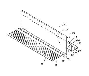
FIGS. 1 and 2 illustrate an example of a "shadow" style
transition molding 10. The molding 10 is a one piece roll
formed sheet metal product, made of .018 gauge pre-painted
steel, for example. The molding is supplied in 10 foot
lengths or industry metric equivalent. The molding 10 has the
general shape of an inverted tee with two horizontal legs 11,
12 and a vertical division leg 13 disposed between the
horizontal legs. FIGS. 8 and 9 illustrate the leg 11 on the
left associated with ceiling drywall 19 and the leg 12 on the
right associated with acoustical tile or panels 15. The
drywall leg 11 has an offset or rise 16 between a minor area
17 adjacent the vertical leg 13 and a larger area 18 distal
from the vertical leg. The offset 16 enables the larger area
18 to be concealed and visually blended in with a sheet of
drywall 19 by taping and coating the large area with joint
compound. As is known in the art, a lower face of the area 18
can be knurled.
A distal edge 20 of the acoustical panel leg 12 has a
downturned hem 21 that contributes to the stiffness and
straightness of the leg. An inner part of the leg 12 adjacent
the vertical leg 13 is formed with horizontal and vertical
sections 22, 23 respectively to produce a "shadow" effect. An
outboard or distal part 24 of the leg 12 is generally coplanar
with the proximal area 17 of the drywall leg 11. In a
completed ceiling installation, the outboard section 24
supports the edge of overlying acoustical tile 15 as depicted
in FIGS. 8 and 9.
The vertical leg 13 is a double layer of the molding
strip. At an upper end, the strip material is folded on
itself while leaving a small hollow 26 that serves to stiffen
the molding 10.
FIGS. 10 and 11 schematically represent a late station in
a roll forming line in which the molding 10 is produced. The
4
CA 02958693 2017-02-20
WO 2016/032810
PCT/US2015/045808
molding stock with its finished cross-sectional profile is
passed between a pair of rolls 28, 29 comprising a rotary
punch and die set. The punch roll 28 has a series of small,
evenly spaced projections or punches on its periphery and the
die roll 29 has a peripheral groove 32 aligned with the
projections 31. The rolls 28, 29 with their peripheries
moving at line speed of the roll forming equipment cooperate
to form a series of center punches or indentations 34 on a
side of the leg 13 facing away from the drywall leg 11. FIG.
6 shows that the center punches 34 are each formed in both
layers of the vertical leg 13. The center punches 34 are
spaced below the upper edge of the vertical leg and serve to
lock the individual layers of the leg 13 together against
shear, thereby stiffening the molding, particularly in torsion
about its length.
The drywall leg 11 is produced with regularly spaced
holes 36 for receiving screws or, less commonly, nails that
attach the molding 10 to a ceiling structure. The holes 36
are formed at a rotary lance station 37 illustrated in FIG.
12. The station 37 has a roll 38 carrying a plurality of
lance punches 39 that project from the roll periphery. The
lance punches 39 pierce the drywall leg 11 as the molding
stock strip passes through the station 37. A die block 41 on
a side of the molding strip stock opposite the punch roll 38
has a close fitting slot 42 that receives the lance punches 39
as they pierce the drywall leg material. The lance punches 39
cut three sides of a square hole 36 leaving a slug 46 from the
hole area attached to the remaining side of the hole. As the
strip moves along the rolling path, the slug 46 is bent back
over the side of the hole at which it is attached by a wipe
block 47 at the exit of the lance station 37. A set of
rollers 48, 49 in the roll forming machine form a nip with
shallow grooves in alignment with the slug 46. The rollers
48, 49 force the slug 46 into the plane of the material of the
5
CA 02958693 2017-02-20
WO 2016/032810
PCT/US2015/045808
leg 11 as shown in FIG. 7. By leaving the slug 46 attached to
the molding stock, the machinery is greatly simplified and
machine maintenance is reduced by avoiding the need to collect
free slugs which can otherwise jam the equipment and/or result
in product defects.
FIG. 8 illustrates the molding 10 installed by anchoring
it to a drywall grid tee or runner 51. A drywall screw 52
located in a hole 36 is driven vertically through a sheet of
drywall 19 and into a flange of the grid tee 51. The holes 36
can be .16 inch square, for example, so that they are larger
than the thread crest of a No. 6 drywall screw. Consequently,
there is no interference with the screw threads and the hole
36 that would cause local buckling of the molding sheet stock
at the hole.
Ideally, the head of the screw 52 is at least partially
countersunk as the perimeter of the hole 36 is drawn inwardly
by the screw head. With the screw head at least partially
countersunk, there is no interference with a taping knife or
trowel used to cover the face of the area 18 of the horizontal
leg 11. The presence of the slug 46 at the hole 36 increases
the ability of the molding 10 to resist pull through of the
screw head so that an installer can quickly set the screw 52
with less concern about over-tightening it such that the head
would completely pull through the hole.
FIG. 8 illustrates the molding 10 additionally attached
to the grid tee 51 by a second drywall screw 54 driven through
the vertical leg 13 at a center punch 34 into the drywall grid
tee web. FIG. 9 illustrates the molding 10 attached with a
self-drilling sheet metal screw 56 driven through the vertical
leg 13 at a center punch 34 into a sheet metal framing member
such as a sheet metal angle 57.
FIGS. 3 and 4 illustrate alternative transition moldings
61, 62 used to practice the invention. The molding 61 of FIG.
3 can be used with narrow faced ceiling grid and the molding
6
CA 02958693 2017-02-20
WO 2016/032810
PCT/US2015/045808
62 of FIG. 4 can be used where a "shadow" look is not
specified.
It should be evident that this disclosure is by way of
example and that various changes may be made by adding,
modifying or eliminating details without departing from the
fair scope of the teaching contained in this disclosure. The
invention is therefore not limited to particular details of
this disclosure except to the extent that the following claims
are necessarily so limited.
7