Note: Descriptions are shown in the official language in which they were submitted.
CA 02958828 2017-02-21
WO 2016/068917 PCT/US2014/062938
1
INTERNALLY TRUSSED HIGH-EXPANSION SUPPORT FOR
REFRACTURING OPERATIONS
TECHNICAL FIELD
The present disclosure relates to wellbore completion operations and, more
particularly,
to a downhole completion assembly for sealing and supporting a previously
perforated section of
production casing.
BACKGROUND
The development of subterranean operations and the processes involved in
removing
hydrocarbons from a subterranean formation typically involve a number of
different steps,
including but not limited to, drilling a wellbore at a desired well site, in
some cases fortifying the
wellbore to prevent its collapse, and treating the region immediately adjacent
the wellbore to
enhance the recovery of the hydrocarbons from the formation into the wellbore.
There are a
number of different ways of enhancing the recovery the hydrocarbons from the
subterranean
formation once the wellbore has been drilled into the region of interest. Over
the past decade or
so, hydraulic fracturing has become one of the widely accepted techniques for
optimizing the
recovery of these hydrocarbons from subterranean formations because it expands
the number and
length of pathways for the oil and gas to make their way from the subterranean
formation to the
wellbore for subsequent recovery.
Presently, there are many wells that were hydraulically fractured, which are
producing
much less than they had previously or never produced as expected. Such wells
include wells
which were completed early in a specific field's development, for example,
when little was
known about how the specific field behaved, wells where insufficient proppant
was placed in the
fractures initially, wells where high production rates caused fracture
collapse, and/or wells where
perforations were spaced too widely. Many of these wells still have sufficient
oil and gas worth
recovering. Indeed, operators stand to benefit from refracturing many of these
wells. However,
before these wells can be refractured, the existing perforations have to be
sealed so that the
fracturing treatment is delivered to the new perforations and not lost through
into the formation
through the old perforations. Accordingly, there is a need for a method and/or
apparatus for
sealing these existing perforations so that the formation can be reperforated
and refractured in
new and more productive zones.
1
SUMMARY
In accordance with a general aspect, there is provided a a method of
refracturing a
subterranean formation having casing installed therein, said method
comprising: (a)
conveying a truss structure and sealing structure disposed thereon into the
casing adjacent a
perforated section of the casing, wherein the perforated section of the casing
comprises a
plurality of perforations formed through the casing, said truss and sealing
structures being
radially expandable between a contracted configuration and an expanded
configuration; (b)
expanding the truss and sealing structures from their contracted
configurations to an
expanded configuration whereby the sealing structure directly contacts and
seals against the
plurality of perforations and thereby reduces or restricts fluid flow between
the subterranean
formation and the inside of the casing; and (c) treating the subterranean
formation through
open perforations at a location that is axially remote from a location
previously fractured.
In accordance with another aspect, there is provided a a downhole completion
system,
comprising: (a) a truss structure, the truss structure radially expandable
between a contracted
configuration and an expanded configuration; and (b) a sealing structure
disposed about the
truss structure, the sealing structure being radially expandable between a
contracted
configuration and an expanded configuration, and said sealing structure being
operable
directly contact and seal against one or more perforations in a perforated
section of casing
when in the expanded configuration so as to restrict the flow of fluids
through the
perforations into a subterranean formation.
la
CA 2958828 2018-06-12
AT Fr IP-N11-7\'' flru'vET: 063718.2995 CA 02958828 2017-02-21
HESWO 2016/06891751 PCT PCT/US2014/062938
BRIEF DESCRIPTION OF THE DRAWINGS
For a more complete understanding of the present disclosure and its features
and
advantages, reference is now made to the following description, taken in
conjunction with the
accompanying drawings, in which:
FIG. 1 illustrates a downhole completion system used to seal previously formed
perforations in a nonproductive zone of an existing wellbore, according to one
or more
embodiments;
FIGs. 2A and 2B illustrate contracted and expanded sections of a truss
structure,
respectively, according to one or more embodiments;
FIGs. 3A and 3B illustrate a truss structure disposed on an expansion tool in
contracted
and expanded configurations, respectively, according to one or more
embodiments; and
FIG. 4 illustrates a sealing structure layered on a truss structure, with an
expansion tool
inserted inside of the truss structure with the truss and sealing structures
in retracted
configurations, according to one or more embodiments;
FIG. 5 is a cross-sectional view of truss and sealing structures in expanded
configurations
showing the sealing structure in engagement with a set of perforations,
according to one or more
embodiments; and
FIG. 6 is a cross-sectional view of truss and sealing structures in expanded
configurations
showing the downhole completion system in sealing engagement with existing
perforations in a
nonproductive zone of a wellbore, according to one or more embodiments.
DETAILED DESCRIPTION
Illustrative embodiments of the present disclosure are described in detail
herein. In the
interest of clarity, not all features of an actual implementation are
described in this specification.
It will of course be appreciated that in the development of any such actual
embodiment,
numerous implementation specific decisions must be made to achieve developers'
specific goals,
such as compliance with system related and business related constraints, which
will vary from
one implementation to another. Moreover, it will be appreciated that such a
development effort
might be complex and time consuming, but would nevertheless be a routine
undertaking for
those of ordinary skill in the art having the benefit of the present
disclosure. Furthermore, in no
way should the following examples be read to limit, or define, the scope of
the disclosure.
The present disclosure provides a downhole completion system that features an
2
,-IfwvET: 063718.2995 CA 02958828 2017-02-21
HESWO 2016/068917J1 PCT PCT/US2014/062938
expandable sealing structure and corresponding internal truss structure that
are capable of being
run through existing production casing and subsequently expanded to support
and seal the
internal surface of a perforated portion of casing so as to restrict the flow
of fluids from the
wellbore into the casing in a previously fractured region. Once the sealing
structure is run to its
proper downhole location, which in most cases will be a previously fractured
portion of
production casing, it may be expanded by any number of expansion tools that
are also small
enough to axially traverse the casing. In operation, the expanded sealing
structure may be useful
in sealing the perforations thereby restricting the influx of fluids into the
casing through the old
perforations. The internal truss structure may be arranged within the sealing
structure and useful
in radially supporting the expanded sealing structure. In some embodiments,
the sealing
structure and corresponding internal truss structure are expanded at the same
time with the same
expansion tool.
The downhole completion system may provide advantages in that it is small
enough to be
able to be run-in through existing casing. When expanded, the disclosed
downhole completion
system may provide sufficient expansion within a perforated portion of the
casing to adequately
restrict the influx of formation fluids. After restricting this flow, a nearby
section of the wellbore
may be perforated and then fractured to form new perforations using fracturing
techniques that
promote increased recovery of production fluids from the formation. As a
result, the
productivity and life of a well may be extended, thereby increasing profits
and reducing
expenditures associated with the well. As will be appreciated by those of
ordinary skill in the
art, the methods and systems disclosed herein may salvage or otherwise revive
certain types of
wells, which were previously thought to be economically unviable.
Referring to Figure 1, illustrated is an exemplary downhole completion system
100,
according to one or more embodiments disclosed. As illustrated, the system 100
may be
configured to be arranged in a previously fractured section 102 of a wellbore
104 to seal
perforations 106 that were previously formed along the casing 108.
Specifically, the system 100
seals against the perforations 106 and thereby creates a fluid impermeable
barrier between the
subterranean formation 109 and the inside of the casing 108. As used herein,
the term "casing"
is intended to be understood broadly so as to encompass casing and/or liners.
For example, the
illustrated casing 108 is cemented into place against the wellbore wall of the
formation 109.
Furthermore, as used, herein, the term or phrase "downhole completion system"
should not be
3
"ru'v.t1`1: 063718,2995 CA 02958828 2017-02-21
HENVO 2016/06891771 PCT PCT/US2014/062938
interpreted to refer solely to wellbore completion systems as classically
defined or otherwise
generally known in the art. Rather, the downhole completion system may also
refer to, or be
characterized as, a downhole fluid transport system. For instance, the
downhole completion
system may not necessarily be connected to any casing or the like. As a
result, in some
embodiments, fluids conveyed through the downhole completion system 100 may
exit the
system 100 into the casing 108, without departing from the scope of the
disclosure.
While Figure 1 depicts the system 100 as being arranged in the fractured
section 102 of a
vertically-oriented wellbore 104, it will he appreciated that the system 100
may be equally
arranged in a horizontal or slanted portion of the wellbore 104, or any other
angular
configuration therebetween, without departing from the scope of the
disclosure. Furthermore, in
some embodiments the system 100 may be arranged in one of several existing
fractured sections
102 along the length of the casing 108.
In present embodiments, the system 100 includes a truss structure and a
sealing structure
disposed around the truss structure. The system 100 may be run in through the
casing 108 until
it reaches the fractured section 102 and is brought into alignment with the
perforations 106 in the
fractured section 102. From this position, as described in detail below, an
expansion tool may be
actuated to expand the truss structure and the sealing structure of the system
100 against an inner
portion of the perforated casing 108, thereby sealing the perforations 106.
Having generally described the context in which the disclosed downhole
completion
system 100 may be utilized, a more detailed description of the components that
make up the
system 100 will be provided. To that end, Figures 2A and 2B illustrate the
truss structure 110 of
the system 100. In one embodiment, the truss structure 110 is formed of a
stainless steel tube,
which has a pattern cut into it that enables it to expand in diameter more
than 50% and up to
approximately 300% without changing axial length, while at the same time
maintaining a useful
strength. It should be noted that any suitable expansion range is contemplated
for the expanded
diameter of the tube without changing its axial length. The tube serves as the
support structure
upon which a separate sealing layer is added. In some embodiments, a feature
of the pattern is
that it enables the the tube to expand radially into a trussed shape that is
internal to the outer
sealing layer. The term "trussed shape" refers to the expanded pattern of the
tube having open
spaces outlined by interconnected portions of the tube (e.g., trusses). These
trusses may provide
additional strength and sealing capabilities.
4
ATTrIDNIE.NI'Q r\r'f'KET: 063718.2995 CA 02958828 2017-02-21
HEWO 2016/068917 PCT PCT/US2014/062938
The sealing element/tube assembly may be expanded in a number of different
ways (e.g.,
a cone, downhole power unit, etc.), but one embodiment is expansion via a
hydraulic inflation
tool 112, such as an inflatable packer, which is shown generally in Figures 3A
and 3B. Figure
3A illustrates the truss structure 110 in its collapsed/contracted
configuration disposed on a
hydraulic inflation tool 112. Figure 3B illustrates the truss structure 110 in
its expanded
configuration upon activation of the hydraulic inflation tool 112. In one
embodiment, the truss
structure 110 is formed of a sheet metal having memory characteristics.
In certain embodiments, the truss structure 110 is formed by cutting the
desired pattern
into a 2.5 to 3 inch diameter, 30 inch long, schedule 40/80 stainless steel
pipe. As those of
ordinary skill in the art will appreciate, the size and composition of the
truss structure 110 is not
limited to this exemplary embodiment. Further, it will be appreciated that the
truss structure 110
may be formed using any suitable manufacturing technique including, but not
limited to, casting,
3D printing, etc. In the illustrated embodiment, the cut pattern is fatmed of
a plurality of rows
114 of perforations disposed equidistant around the circumference of the truss
structure 110.
These perforations may form a plurality of expandable cells 122 defined on the
truss structure
110. Each row 114 is formed of a plurality of generally opposing,
longitudinally offset arc-
shaped perforations 116, each having a dimple 118 formed in the approximate
mid-section of the
arc, as shown in Figure 2A. The arc-shaped perforations 116 are arranged along
the length of the
truss structure 110 and have holes 120 formed at the beginning and end of each
arc. The holes
120 and the arcs 116 may completely penetrate the steel structure of pipe. In
other
embodiments, the arcs 116 themselves may only partially penetrate through the
pipe wall. In
still further embodiments, neither the arcs 116 nor the holes 120 may
penetrate through the pipe
wall. The pattern is preferably cut using a water jet, but may also be cut
using a laser.
Each of the expandable cells 122 includes a perimeter that is defined by the
arc-shaped
perforations 116, the dimples 118, and the holes 120. Upon expansion of the
cells 122, the arc-
shaped perforations open up and form opposing offset generally pie-shaped
openings in the body
of the truss structure 110, which are formed along the length of the pipe, as
shown in Figure 2B.
It should be apparent that other embodiments are possible, such as where the
truss structure 110
uses linear rather than arc-shaped perforations 116. In other embodiments, the
perforations 116
are not generally opposing.
It should be noted that any suitable shaped perforations 116 that permit the
truss structure
5
r`r`rwET: 063718.2995 CA 02958828 2017-02-21
HESWO 2016/068917j' per PCT/US2014/062938
110 to expand may be used in other embodiments. In addition, any suitable
number of such
perforations 116 may be utilized to provide the desired expansion.
Furthermore, any suitable
relationship between the perforations 116 may be contemplated in the disclosed
embodiments.
Still further, the openings 122 in the body of the truss structure 110 may
have any suitable
shaped upon expansion of the truss structure 110.
The run-in configuration of the downhole completion system 100 is shown in
Figure 4,
with a sealing structure 130 disposed on the truss structure 110. The sealing
structure 130 is an
elongate tubular member. In some embodiments, the sealing structure 130 may be
formed by
coiling a sealing material around the truss structure 110. The sealing
material may be formed of
rubber; thermoset plastics; thermoplastics; fiber-reinforced composites;
cementious
compositions; corrugated, crenulated, circular, looped or spiral metal or
metal alloy; any
combination of the forgoing; or any other suitable sealing material. As
illustrated, the truss
structure 110 may be nested inside the sealing structure 130 when the sealing
structure 130 is in
its contracted configuration. In some embodiments, multiple truss structures
110 may be nested
to create a longer length.
In some embodiments, the sealing structure 130 may further include a sealing
element
132 disposed about at least a portion of the outer circumferential surface of
the sealing structure,
as illustrated in Figure 5. In some embodiments, an additional layer of
protective material 134
may surround the outer surface of the sealing element 132 to protect the
sealing element 132 as it
is advanced through the wellbore. The protective material 134 may further
provide external
support to the sealing structure 130. For example, the protective material 134
may provide
external support to the sealing structure 130 (and truss structure) by holding
the sealing structure
130 under a maximum running diameter prior to the placement and expansion of
the truss
structure within the casing 108. The term "maximum running diameter" refers to
a diameter
which the sealing structure 130 is not exceed while the downhole completion
system 100 is
being run through tubing in the wellbore. Indeed, the protective material 134
may exert a slight
compressive force on the sealing structure 130 (and the truss structure) to
maintain these
structures in a compressed position while the system is lowered through the
wellbore. After
reaching the appropriate position in the wellbore, an inflation tool, as
described above, may exert
a force on the inside surface of the truss structure that opposes and
overcomes the compressive
force from the protective material 134 in order to expand the completion
system 100.
6
""nv ET: 063718.2995 CA 02958828 2017-02-21
HESWO 2016/068917T1 PCT PCT/US2014/062938
In operation, the sealing element 132 may be configured to expand as the
sealing
structure 130 expands and ultimately engage and seal against the inner
diameter of the casing
108. In some embodiments, the sealing element 132 may be arranged at two or
more discrete
locations along the length of the sealing structure 130. In some embodiments,
the sealing
element 132 may be arranged at a location along the length of the sealing
structure 130 that
corresponds with the location of the perforations 106 through which production
fluids would
otherwise enter the casing 108. The sealing element 132 may be made of an
elastomer, a rubber,
or any other suitable material. The sealing element 132 may further be formed
from a swellable
or non-swellable material. In at least one embodiment, the sealing element 132
may be a
swellable elastomer that swells in the presence of at least one of water and
oil.. However, it will
be appreciated than any suitable swellable material may be employed and remain
within the
scope of the present disclosure.
In other embodiments, the material for the sealing elements 132 may vary along
the
sealing section in order to create the best sealing available for the fluid
type that the particular
seal element may be exposed to. For instance, one or more bands of sealing
materials may be
located as desired along the length of the sealing section. The material used
for the sealing
element 132 may include swellable elastomeric, as described above, and/or
bands of viscous
fluid. The viscous fluid, for instance, may be an uncured elastomeric that
will cure in the
presence of well fluids. The viscous fluid may include a silicone that cures
with water in some
embodiments. In other embodiments, the viscous fluid may include other
materials that are a
combination of properties, such as a viscous slurry of the silicone and small
beads of ceramic or
cured elastomeric material. The viscous material may be configured to better
conform to the
annular space between the expanded sealing structure and the varying shape of
the casing 108
and/or the perforations 106. It should be noted that to establish a seal, the
material of the sealing
element 132 does not need to change properties, but only have sufficient
viscosity and length to
remain in place the life of the well. The presence of other fillers, such as
fibers, may enhance the
viscous material.
As illustrated, and as will be discussed in greater detail below, at least one
truss structure
110 may be generally arranged within a corresponding sealing structure 130 and
may be
configured to radially expand to seal a previously fractured portion of
casing. For example,
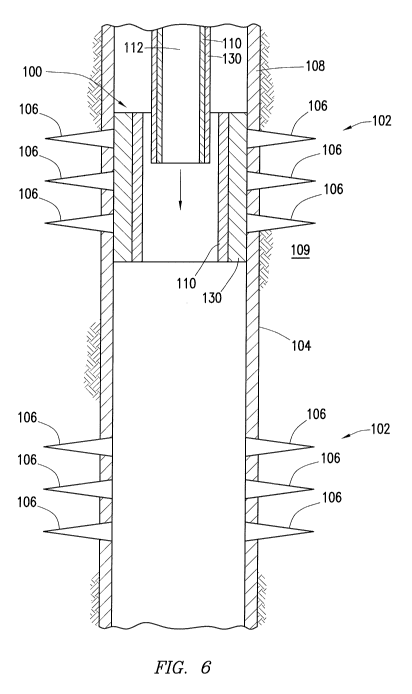
Figure 6 illustrates a cross-section of the fractured section 102 of casing
108 being sealed by the
7
""ET: 063718.2995 CA 02958828 2017-02-21
"
HESWP 6/Q.68'7jii
PCT PCT/US2014/062938
downhole completion system 100 described above. As illustrated, the downhole
completion
system 100 seals off existing perforations 106 through which production fluid
would normally
flow from the subterranean formation into the casing 108. In the downhole
completion system
100, the expanded truss structure 110 holds the sealing structure 130 against
these perforations
.. 106, thereby sealing the fractured section 102 so that fracturing fluids
may be provided to the
formation 106 through the new perforations and not through the old
perforations 106. As
illustrated, there is no expansion tool present within the system 100, since
the expansion tool
may function as a deployment device that is reniovable after being used to
expand the system
100 into sealing engagement with the fractured section 102 of casing 108.
In some embodiments, the disclosed system 100 may be capable of sealing .75
inch
perforations 106. In some embodiments, the system 100 may be able to hold at
least
approximately 10,000 psi of burst pressure for repeated cycles, which may
enable the seals
formed by the downhole completion system 100 against the perforations 106 to
withstand
pressure forces caused by sending pressurized fracturing fluids downhole to
refracture multiple
.. wellbore zones.
During installation, the system 100 may be combined with a mechanical
connection to
the surface for translating the system 100 through the casing 108. The
mechanical connection
may include a conveyance device used to transport the sealing structure 130
and truss structure
110 in their respective contracted configurations through the casing 108 to
the previously
fractured section 102. The conveyance device may include a wireline, a
slickline, coiled tubing
or jointed tubing. In some embodiments, the system 100 may be run into the
fractured section
102 in a contracted state on an expansion tool coupled to the mechanical
connection prior to
expansion via the expansion tool. After expansion of the system 100, the
expansion tool may be
released and translated out of the casing 108 via the mechanical connection.
In some
embodiments, the system 100 may be positioned within the fractured section 102
through the use
of a spinner, a casing-collar locator, tagging off of a known restriction
(e.g., landing nipple), or
any other method. In some embodiments, the system 100 may be equipped with a
sensor for
determining the position of the system 100 with respect to the fractured
section 102 and the
perforations 106 that need to be sealed.
As mentioned above, the downhole completion system 100 may be utilized to seal
a
relatively old fractured section 102 of the casing 108 so that another section
of the formation
8
CA 02958828 2017-02-21
ATT"'"''"T".ET: 063718.2995
HESWO 2016/068917_11 PCT PCT/US2014/062938
may then be fractured. This is illustrated in FIG. 1, which shows a new
location 150 for
refracturing the wellbore 104, this location 150 being axially removed from
the initial fractured
section 102. After sealing the old perforations 106 of the fractured section
102 via the system
100, it may be desirable to refracture the formation in the new location 150
by perforating the
.. casing 108 at this location 150 and subsequently or simultaneously treating
the formation with,
for example, pressurized fracturing fluids and proppant particulates. By
sealing the old
perforations 106, the downhole completion system 100 may direct the fracturing
fluids and other
treatments used in refracturing operations through perforations formed in the
new location 150
instead of diverting the fluid through the old perforations 106. In addition,
sealing the
perforations 106 may prevent production fluids produced via the newly
fractured section from
flowing into the casing 108 via the old perforations 106.
In some embodiments, multiple different fractured sections 102 located along
the
wellbore 104 may need to be sealed throughout the life of the well. In such
situations, multiple
downhole completion system 100 may be deployed into the wellbore 104 to seal
the fractured
sections 102. As illustrated in Figure 6, one or more of the systems 100 may
be translated (in a
contracted configuration) through an expanded system 100 that is already
sealing the
perforations 106 at an upper fractured section 102. In such embodiments the
inner diameter of
the truss structure 110 in the expanded configuration may be greater than the
outer diameter of
the downhole completion system 100 in the contracted configuration. Thus,
sealing can be
provided along the perforations 106 in the casing. In a similar way, it may be
desirable to lower
additional tools, such as a perforating device and a fracturing device,
through the expanded truss
structure 110 in order to perform a refracturing operation on lower wellbore
zones. The
perforating device may include any suitable device for perforating the casing
108. The
additional tools may be lowered (e.g., via wireline and the like) through the
casing 108 and
through the truss structure 110 until they reach a desired lower location of
the wellbore 104
where additional perforations are to be created and enhanced.
The disclosed downhole completion system 100 may be deployed directly into the
casing
108 to seal perforations 106 at any point along the length of the casing 108
and at any point
during production. This allows flexibility in sealing off various fractured
sections 102 that are
no longer producing, and performing refracturing operations in different zones
to increase the
amount of formation fluids produced through the wellbore 104. An operator does
not have to
9
ATIV \13hi L'V'C' r\rµnitET: 063718.2995 CA 02958828 2017-02-21
HESWO 2016/068917H PCT PCT/US2014/062938
anticipate which zones of the wellbore 104 might need to be refractured during
the lifetime of
the well. In addition, the use of the system 100 to seal the perforations 106
at upper fractured
sections 102 of the wellbore does not prevent the perforation and treatment of
another section of
the wellbore 104 further down the wellbore 104.
Embodiments disclosed herein include:
A. A method of refracturing a subterranean formation having
casing installed therein
that includes conveying a truss structure and sealing structure disposed
thereon into the casing
adjacent a perforated section of the casing. The truss and sealing structures
are radially
expandable between a contracted configuration and an expanded configuration.
The method also
includes expanding the truss and sealing structures from their contracted
configurations to an
expanded configuration whereby the sealing structure seals against the
perforated section of the
casing and thereby reduces or restricts fluid flow between the subterranean
formation and the
inside of the casing, and treating the subterranean formation through open
perforations at a
location that is axially removed from a location previously fractured.
B. A downhole completion system includes a truss structure, the truss
structure and a
sealing structure disposed about the truss structure. The truss structure is
radially expandable
between a contracted configuration and an expanded configuration. The sealing
structure is
radially expandable between a contracted configuration and an expanded
configuration. The
sealing structure is operable to seal one or more perforations in a perforated
section of easing
when in the expanded configuration so as to restrict the flow of fluids
through the perforations
into a subterranean formation.
Each of the embodiments A and B may have one or more of the following
additional
elements in combination: Element 1: further including perforating the casing
at the location that
is axially removed from the location previously fractured. Element 2: further
including
conveying the sealing and truss structures into the casing simultaneously, the
truss structure
being nested inside the sealing structure when the sealing structure is in its
contracted
configuration. Element 3: wherein radially expanding the truss structure into
its expanded
configuration further comprises expanding a plurality of expandable cells
defined on the truss
structure. Element 4: wherein the axial length of the truss structure in the
contracted and
expanded configurations is substantially the same. Element 5: wherein a
diameter of the truss
structure is expanded by more than 50% when the truss structure is expanded
from the contracted
ATT")-mu'v'Q rv'f1/ET: 063718.2995 CA 02958828 2017-02-21
HESWO 2016/06891711 PCT PCT/US2014/062938
configuration to the expanded configuration. Element 6: further including
conveying the truss
structure and the sealing structure into the casing until the truss structure
and the sealing
structure are disposed adjacent the perforated section of the casing based on
sensor feedback, and
radially expanding the truss and sealing structures from their contracted
configurations to the
expanded configuration when the truss and sealing structures are disposed
adjacent the
perforated section of the casing. Element 7: further including conveying a
second truss structure
with a second sealing structure disposed thereon in a contracted configuration
into the casing and
through the expanded truss structure. Element 8: further comprising conveying
a perforating
device into the casing and through the expanded truss structure, and
perforating the subterranean
formation via the perforating device at the location that is axially removed
from the location
previously fractured.
Element 9: further including a conveyance device to transport the sealing and
truss
structures in their respective contracted configurations through the casing to
the perforated
section of casing. Element 10: wherein the conveyance device is selected from
the group
consisting of wireline, sliekline, coiled tubing and jointed tubing. Element
11: further including
a deployment device to radially expand the sealing and truss structures from
their respective
contracted configurations to their respective expanded configurations. Element
12: wherein the
deployment device is selected from the group consisting of a hydraulic
inflation tool and an
inflatable packer. Element 13: wherein when in the expanded configuration the
truss structure
radially supports the sealing structure. Element 14: wherein the truss
structure includes a
plurality of expandable cells. Element 15: wherein the truss structure has a
diameter which
expands by more than 50% when the truss structure is expanded from the
contracted
configuration to the expanded configuration. Element 16: wherein the axial
length of the truss
structure in the contracted and expanded configurations is substantially the
same. Element 17:
wherein an inner diameter of the truss structure in the expanded position is
greater than an outer
diameter of the sealing structure in the contracted position. Element 18:
wherein a swellable
material is disposed about at least a portion of the sealing structure.
Although the present disclosure and its advantages have been described in
detail, it
should be understood that various changes, substitutions and alterations can
be made herein
without departing from the spirit and scope of the disclosure as defined by
the following claims.
11