Note: Descriptions are shown in the official language in which they were submitted.
CA 02958857 2017-02-21
WO 2016/028925
PCT/US2015/045950
GRAPHICAL DISPLAY FOR BIRD OR BAT DETECTION AND IDENTIFICATION
PRIORITY
[0001] This application claims priority to U.S. Provisional Patent Application
No.
62/040,081 titled "BIRD OR BAT DETECTION AND IDENTIFICATION FOR WIND
TURBINE RISK MITIGATION," filed on August 21, 2014, and U.S. Patent
Application No.
14/829,465 titled "GRAPHICAL DISPLAY FOR BIRD OR BAT DETECTION AND
IDENTIFICATION," filed on August 18, 2015, both of which applications are
incorporated
herein by reference in their entirety.
TECHNICAL FIELD
[0002] This disclosure relates generally to systems and methods for
assessing and/or
reducing the risk from wind turbines to birds and/or bats.
BACKGROUND
[0003] The spinning turbine blades of wind farms pose a risk to birds or
bats that fly
through the volume swept by the turbine blades. Some government entities may
require wind
farms to mitigate that risk, particularly for certain bird or bat species
protected by law or
government regulations. For example, these government entities may require
that mitigation
of the risk to Golden Eagles or Bald Eagles from a proposed wind farm be
demonstrated
before installation of the wind farm is permitted. Other governments may not
require a
permit, but may still issue penalties or fines for those wind farms that harm
government
identified birds or other animals.
[0004] Attempts to mitigate the risk posed by wind farms to protected bird
or bat species
typically involve curtailing (e.g., slowing or shutting down) operation of
wind turbines when
it is determined that protected birds or bats may be present. Existing
mitigation methods
typically cannot specifically identify birds or bats that they detect, and may
therefore curtail
operation of wind turbines more often than is necessary to mitigate risk to
protected bird and
bat species. This results in loss of energy and revenue. Further, existing
mitigation methods
typically have a high capital cost.
1
CA 02958857 2017-02-21
WO 2016/028925
PCT/US2015/045950
DISCLOSURE OF THE INVENTION
[0005] This specification discloses systems and methods that employ
automated optical
imaging technology to mitigate the risk posed by wind turbines to protected
bird and/or bat
species, other types of objects, or combinations thereof and related systems
and methods that
employ automated optical imaging to assess such risk prior to or after
construction of a wind
farm by surveying bird and/or bat populations, surveying other types of risks,
or
combinations thereof in the vicinity of the wind farm site.
[0006] In one aspect of the invention, an automated system for mitigating
risk from a
wind turbine includes a plurality of optical imaging sensors and a controller.
The controller
is configured to automatically receive and analyze images from the optical
imaging sensors,
to automatically send a signal to curtail operation of the wind turbine to a
predetermined risk
mitigating level when the controller determines from images from the optical
imaging sensors
that an is at risk from the wind turbine, and to subsequently automatically
send a signal to
resume normal operation of the wind turbine when the controller determines
from additional
images from the optical imaging sensors that there is no longer risk from the
wind turbine to
an airborne object of the one or more predetermined species.
[0007] The controller may be configured to determine whether each bird or
bat it detects
in images from the optical imaging sensors is a member of a particular
predetermined species
before the detected bird or bat is closer to the wind turbine than the
distance the particular
predetermined species can fly at a characteristic speed of the particular
predetermined species
in the time required to curtail operation of the wind turbine to the
predetermined risk
mitigating level. The characteristic speed of the particular predetermined
species may be, for
example, the average horizontal flight speed of the predetermined species or
the maximum
horizontal flight speed of the predetermined species.
[0008] In some variations the predetermined species include Golden Eagles.
In some of
these variations the controller determines whether each bird or bat it detects
in images from
the optical imaging sensors is a Golden Eagle before the detected bird or bat
is closer than
about 600 meters to the wind turbine. The controller may detect at a distance
greater than
about 800 meters each bird or bat that it subsequently determines is a Golden
Eagle.
[0009] In some variations the predetermined species include Bald Eagles. In
some of
these variations the controller determines whether each bird or bat it detects
in images from
the optical imaging sensors is a Bald Eagle before the detected bird or bat is
closer than about
2
CA 02958857 2017-02-21
WO 2016/028925
PCT/US2015/045950
600 meters to the wind turbine. The controller may detect at a distance
greater than about
800 meters each bird or bat that it subsequently determines is a Bald Eagle.
[0010] The plurality of optical imaging sensors may be arranged with a
combined field of
view of about 360 degrees or more around the wind turbine. The optical imaging
sensors
may be arranged with overlapping fields of view. In some variations, at least
some of the
optical imaging sensors are attached to a tower supporting the wind turbine.
In some
variations one or more of the optical imaging sensors is arranged with a field
of view directly
above the wind turbine.
[0011] The system may comprise a deterrent system configured to deploy bird
and/or bat
deterrents, such as flashing lights or sounds for example, to deter birds
and/or bats from
approaching the wind turbine. In such variations the controller may be
configured to
automatically send a signal to the deterrent system to deploy a bird or bat
deterrent if the
controller determines from images from the optical imaging sensors that a bird
or bat of the
one or more predetermined species is approaching the wind turbine.
[0012] In another aspect, an automated system for mitigating risk from a
wind turbine to
birds or bats of one or more predetermined species comprises a plurality of
optical imaging
sensors and a controller. The controller is configured to automatically
receive and analyze
images from the optical imaging sensors and to automatically send a signal to
the deterrent
system to deploy a bird or bat deterrent if the controller determines from
images from the
optical imaging sensors that a bird or bat of the one or more predetermined
species is
approaching the wind turbine.
[0013] The controller may be configured to determine whether each bird or
bat it detects
in images from the optical imaging sensors is a member of a particular
predetermined species
before the detected bird or bat is closer to the wind turbine than the
distance the particular
predetermined species can fly at a characteristic speed of the particular
predetermined species
in the time required to curtail operation of the wind turbine to a
predetermined risk mitigating
level. The characteristic speed of the particular predetermined species may
be, for example,
the average horizontal flight speed of the predetermined species or the
maximum horizontal
flight speed of the predetermined species.
[0014] In some variations the predetermined species include Golden Eagles.
In some of
these variations the controller determines whether each bird or bat it detects
in images from
the optical imaging sensors is a Golden Eagle before the detected bird or bat
is closer than
3
CA 02958857 2017-02-21
WO 2016/028925
PCT/US2015/045950
about 600 meters to the wind turbine. The controller may detect at a distance
greater than
about 800 meters each bird or bat that it subsequently determines is a Golden
Eagle.
[0015] In some variations the predetermined species include Bald Eagles. In
some of
these variations the controller determines whether each bird or bat it detects
in images from
the optical imaging sensors is a Bald Eagle before the detected bird or bat is
closer than about
600 meters to the wind turbine. The controller may detect at a distance
greater than about
800 meters each bird or bat that it subsequently determines is a Bald Eagle.
[0016] The plurality of optical imaging sensors may be arranged with a
combined field of
view of about 360 degrees or more around the wind turbine. The optical imaging
sensors
may be arranged with overlapping fields of view. In some variations, at least
some of the
optical imaging sensors are attached to a tower supporting the wind turbine.
In some
variations one or more of the optical imaging sensors is arranged with a field
of view directly
above the wind turbine.
[0017] In one aspect of the invention, a graphical user interface produced
by an
application program operating on a computing device having a display device
associated
therewith includes an application program window presented on the at least one
display
device. The application program window is generated by the application program
operating
on the computing device. The application program window displays a real-time
graphical
representation of a wind farm, and the application program receives real-time
information
pertaining to the wind farm from a remote server over a network. The
application program
window displays an airborne object located in real-time on the display device.
[0018] In some examples, the remote server is in communication with an
array of image
capturing devices positioned within the wind farm over the network. The array
of image
capturing devices may include a plurality of low resolution cameras and at
least one high
resolution camera, and the remote server initiates the at least one high
resolution camera to
capture a high resolution image of the airborne object captured with at least
one of the
plurality of low resolution cameras.
[0019] The graphical user interface may also include a second display
device coupled to
the application program. The second display device may display a real-time
image of the
airborne object when an incoming object enters a predetermined boundary
surrounding the
wind farm. Also, the graphical user interface may include a second window
within the
application program window, the second window displaying a real-time image of
the airborne
object when an object enters a predetermined boundary surrounding the wind
farm.
4
CA 02958857 2017-02-21
WO 2016/028925
PCT/US2015/045950
[0020] The application program window may displays a classification of the
airborne
object as the remote server determines the classification. The application
program window
may display a behavioral pattern of the airborne object when the airborne
object is an animal.
The remote server may be in communication with a radar system proximate at
least one high
resolution camera, and the remote server initiates the radar system to
determine a location
and travel trajectory of the airborne object.
[0021] The application program window may display a graphical
representation of the
location and the travel trajectory of the airborne object within the wind
farm. The application
program window may display a graphical representation of an alert status of
the airborne
object based at least in part on an alert threshold. The remote server may
initiates curtailment
activities of the wind farm based at least in part on a real-time location of
the airborne object,
wherein the application program window displays the curtailment activities.
The application
program window may display meteorological information pertaining to the wind
farm. The
wind farm may be a first wind farm and the application program window changes
the display
device to a second wind farm. The application program window display
alternates between
the first wind farm and the second wind farm. The application program window
may
prioritize the display device to present an event occurring at one of the
first wind farm or the
second wind farm.
[0022] In another aspect of the invention, a graphical user interface
produced by an
application program operating on a computing device having a display device
associated
therewith includes an application program window presented on the at least one
display
device, said application program window being generated by the application
program
operating on the computing device. The application program window displays a
real-time
graphical representation of a wind farm, the real-time graphical
representation received by
the application program from a remote server over a network. The remote server
receives
real-time location information from a radar system proximate the wind farm,
wherein the
application program window displays an airborne object located in real-time on
the display
device. The application program classifies the airborne object as an airborne
animal and
generates an event based at least in part on a classification.
[0023] In yet another aspect of the invention, a graphical user interface
produced by an
application program operating on a computing device having a display device
associated
therewith includes an application program window presented on the at least one
display
device, the application program window being generated by the application
program
CA 02958857 2017-02-21
WO 2016/028925
PCT/US2015/045950
operating on the computing device. The application program window displays a
real-time
graphical representation of a wind farm, the real-time graphical
representation received by
the application program from a remote server over a network. The remote server
receives
real-time location information from a radar system proximate the wind farm
where the
application program window displays a location and trajectory of an airborne
object located
in real-time on the display device. The remote server is in communication with
an array of
image capturing devices including a plurality of low resolution cameras and at
least one high
resolution camera where the application program classifies the airborne object
as an airborne
animal based at least in part on images captured by the array of image
capturing devices and
generates an event based at least in part on a classification. The remote
server initiates
curtailment activities of the wind farm based at least in part on a real-time
location of the
airborne object, wherein the application program window displays the
curtailment activities.
[0024] In another aspect, an automated system for surveying the population
of birds or
bats of one or more particular species of interest comprises a plurality of
optical imaging
sensors and a controller. The controller is configured to automatically
receive and analyze
images from the optical imaging sensors and to automatically determine whether
birds or bats
detected in images from the optical imaging sensors are members of the one or
more
particular species of interest. The particular species of interest may
comprise, for example,
Bald Eagles and/or Golden Eagles.
[0025] In one embodiment, an automated system for mitigating risk from a
wind farm is
described. The automated system may include an array of a plurality of image
capturing
devices independently mounted in a wind farm. The array may include a
plurality of low
resolution cameras and at least one high resolution camera. The plurality of
low resolution
cameras may be interconnected and may detect a spherical field surrounding the
wind farm.
A server may be in communication with the array of image capturing devices.
The server
may automatically analyze images to classify an airborne object captured by
the array of
image capturing devices in response to receiving the images.
[0026] The array of image capturing devices may coordinate the capturing of
a
stereoscopic image of the airborne object. The server may be connected to a
plurality of
wind towers, wherein the server may be capable of initiating mitigation
efforts of the wind
towers. The mitigation activities may curtail functionality of blades of the
wind tower. The
mitigation activities may initiate one or more deterrent activities, wherein
the deterrent
activities may include flashing lights and sounds.
6
CA 02958857 2017-02-21
WO 2016/028925
PCT/US2015/045950
[0027] A plurality of towers may be strategically placed around the wind
farm to provide
360 degrees of optical coverage of each wind tower in the wind farm. The
plurality of towers
may be equipped with the plurality of image capturing devices. The plurality
of towers may
be equipped with meteorological instrumentation, the meteorological
instruments may be
connected to the server. The meteorological instruments may stream weather
conditions to
the server. The server may be configured to use the weather conditions to aid
in identifying a
behavioral pattern to classify the flying object.
[0028] A radar system may be proximate the at least one high resolution
camera. The at
least one high resolution camera may be equipped with a pan and tilt system
capable of near
360 motion. An observation zone may surround each plurality of image capturing
devices,
wherein each observation zone may overlap. The array may further include at
least one wide
view imaging system, the wide view imaging system may comprise a view range
between
180 degrees and 90 degrees.
[0029] In another embodiment, a method of mitigating risk from a wind farm
is
described. The method may include detecting one or more airborne objects
through a low
resolution camera, activating a high resolution camera to provide improved
imagery, and
transmitting, automatically through a computing device, improved imagery data
to a cloud
server. The method may include classifying, through the cloud server, the
airborne object
based at least in part on the improved imagery, monitoring the airborne object
with the high
resolution camera as it enters a wind farm based at least in part on the
classification when the
airborne object is classified as at least one of the predetermined species.
The method may
also include activating mitigation efforts within the wind farm when the
flying object meets a
threshold classification and a threshold location.
[0030] The method may further include gathering one or more meteorological
data points
from one or more meteorological instruments proximate the high resolution
camera and
transmitting the meteorological data points to a cloud server. A cloud server
may analyze a
behavior of the flying object based at least part on the meteorological data
points. Image data
and meteorological data points may be streamed to the cloud server. The cloud
server may
update a travel trajectory of the flying object and a behavioral
categorization based at least in
part on the streaming data.
[0031] Activating mitigation efforts may further include curtailing,
automatically,
operation of a wind tower based at least in part on the threshold
classification and threshold
location. The threshold location may comprise a predetermined distance from a
wind tower
7
CA 02958857 2017-02-21
WO 2016/028925
PCT/US2015/045950
based at least in part on a travel trajectory of the flying object and a
travel speed of the flying
object. An event log may be generated when a flying object enters the wind
farm. The event
information may be recorded including object classification, travel
information, and
mitigation efforts relating to the event. The event information may be stored
in a cloud
server for a predetermined period of time. A location of the airborne object
may be
determined using a radar system proximate the high resolution camera.
[0032] In another embodiment, an automated system for mitigating risk from
a wind farm
is described. The automated system may include a plurality of image capturing
devices
independently mounted on a detection system tower in a wind farm. The
plurality of image
capturing devices including a plurality of low resolution cameras and at least
one high
resolution camera. The plurality of low resolution cameras may be
interconnected and may
detect a spherical field surrounding the wind farm. A server may be in
communication with
the array of image capturing devices. The server may analyze images to
classify a flying
object captured by the array of imaging capturing devices in response to
receiving the
images.
[0033] These and other embodiments, features and advantages of the present
invention
will become more apparent to those skilled in the art when taken with
reference to the
following more detailed description of the invention in conjunction with the
accompanying
drawings that are first briefly described.
BRIEF DESCRIPTION OF THE DRAWINGS
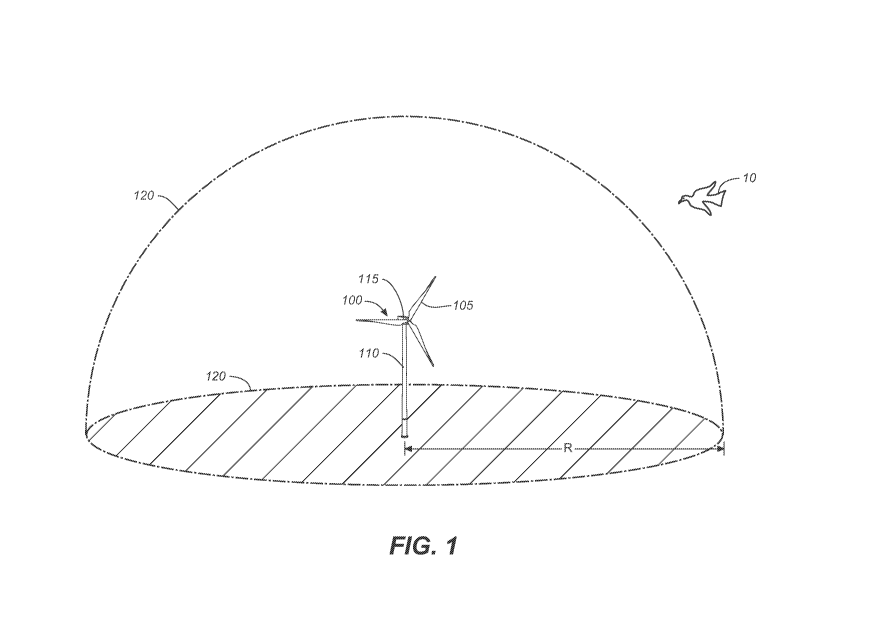
[0034] Figure 1 is an exemplary side perspective view of a wind turbine
illustrating a
volume of space around the wind turbine defined by an example bird or bat risk
mitigation
methods and systems disclosed herein.
[0035] Figure 2 is an exemplary top perspective view of the wind turbine
and bird or bat
risk mitigation volume illustrated in Figure 1.
[0036] Figure 3 is an exemplary top perspective view of a wind farm
illustrating risk
mitigation volumes defined by an example bird or bat risk mitigation methods
and systems
disclosed herein, as well as the trajectory of a bird flying through the wind
farm and
triggering curtailment for some wind turbines but not others.
[0037] Figure 4 shows an exemplary view of a wind turbine to which optical
imaging
sensor modules are mounted according to an example bird or bat risk mitigation
methods and
systems disclosed herein.
8
CA 02958857 2017-02-21
WO 2016/028925
PCT/US2015/045950
[0038] Figure 5 shows an exemplary view of a wind turbine to which optical
imaging
sensor modules are mounted according to an example bird or bat risk mitigation
methods and
systems disclosed herein.
[0039] Figure 6 shows an exemplary view of a wind turbine to which optical
imaging
sensor modules are mounted according to an example bird or bat risk mitigation
methods and
systems disclosed herein.
[0040] Figure 7 shows an example block diagram of a system for mitigating
risk from a
wind turbine to birds or bats disclosed herein.
[0041] Figure 8 is a top perspective view of an example of a wind turbine
farm with an
array of image capturing devices disclosed herein.
[0042] Figure 9 shows an exemplary view of a detection system tower
disclosed herein.
[0043] Figures 10A, 10B, 10C, 10D, and 10E show an exemplary graphical user
interface
as disclosed herein.
[0044] Figure ibis an exemplary flow diagram pertaining to detection
systems as
disclosed herein.
[0045] Figure 12 is an exemplary flow diagram pertaining to detection
systems as
disclosed herein.
BEST MODE(S) FOR CARRYING OUT THE INVENTION
[0046] The following detailed description should be read with reference to
the drawings,
in which identical reference numbers refer to like elements throughout the
different figures.
The drawings, which are not necessarily to scale, depict selective embodiments
and are not
intended to limit the scope of the invention. The detailed description
illustrates by way of
example, not by way of limitation, the principles of the invention. This
description will
enable one skilled in the art to make and use the invention, and describes
several
embodiments, adaptations, variations, alternatives and uses of the invention.
[0047] For the purposes of this disclosure, the term "airborne object"
generally refers to
animals or objects that employ aerial locomotion. This aerial locomotion may
be powered or
unpowered. These airborne objects may include flying or gliding objects or
animals such as
birds, bats, insects, other types of mammals, other types of birds, drones,
aircraft, projectiles,
other types of airborne objects, or combinations thereof
[0048] Referring to Figure 1 (side view) and Figure 2 (top view), this
specification
discloses automated systems and methods that employ optical imaging technology
to detect
birds, bats, or other types of objects (e.g., bird 10) in flight near a wind
turbine 100,
9
CA 02958857 2017-02-21
WO 2016/028925
PCT/US2015/045950
determine whether or not the detected bird, bat, or object is of one or more
particular
protected species or group requiring risk mitigation (e.g., a Golden Eagle, a
Bald Eagle,
government drone), and based on that determination decide whether or not to
curtail
operation of the wind turbine 100 and/or whether or not to employ deterrent
measures to
deter the detected bird, bat, or object from approaching the wind turbine 100.
The systems
and methods may, for example, positively identify a detected bird, bat, or
object to be a
member of a protected species or group for which risk is to be mitigated,
positively identify a
detected bird, bat, or object to be a member of a species for which risk need
not be mitigated,
or determine that a detected bird, bat, or object is not a member of a
protected species or
group for which risk is to be mitigated without identifying the species of the
bird, bat, or
object. In some cases, a protected species is defined by a government in which
jurisdiction
the wind farm is located. But, in other examples, the system may include a
list of species that
it classifies as a "protected species." In other examples, the species that
are considered to be
a protected species may be based on international treaties, non-governmental
organizations,
protection groups, industry experts, scientific studies, religious groups,
other individuals,
other organizations, or combinations thereof
[0049] In these systems and methods the birds, bats, or object may be first
imaged at a
distance from the wind turbine 100 greater than or equal to a distance R, and
the decisions to
curtail or not to curtail operation of the wind turbine 100 and to deploy or
not to deploy
deterrent measures may be made before the bird, bat, or object approaches
closer than
distance R to the wind turbine 100. The distance R is selected to provide
sufficient time for
operation of the wind turbine 100 to be curtailed before the detected bird or
bat is likely to
reach the volume swept by the wind turbine blades 105, if the bird, bat,
object is flying
toward the wind turbine 100 at a speed characteristic of a protected species
for which risk is
to be mitigated. A characteristic speed of a bird or bat species may be, for
example, an
average horizontal flight speed or a maximum horizontal flight speed.
[0050] Hence the distance R may be selected, for example, to be greater
than or equal to
the distance that a bird or bat of the protected species for which risk is to
be mitigated can fly
at that species' known average horizontal flight speed in the time interval
required to curtail
operation of the wind turbine 100. Alternatively, the distance R may be
selected for example
to be greater than or equal to the distance that a bird or bat of the
protected species for which
risk is to be mitigated can fly at that species' known maximum horizontal
flight speed in the
time interval required to curtail operation of the wind turbine.
CA 02958857 2017-02-21
WO 2016/028925
PCT/US2015/045950
[0051] If the methods and systems are used to mitigate risk from the wind
turbine 100 for
more than one protected species of bird and/or bat, R may be determined for
example using a
characteristic speed of the fastest of the protected species for which risk is
to be mitigated.
Alternatively, a separate distance R may be determined for each protected
species for which
risk is to be mitigated.
[0052] The distance R may be measured for example from near the base of the
wind
turbine tower 110 as shown in Figure 1, from the wind turbine nacelle 115, or
from any other
suitable location on the wind turbine or its support structure. R may
conveniently be
measured from at or near the location of one or more optical imaging sensors
(further
described below) employed in the systems and methods, but this is not
required. In the
illustrated example, R defines the boundary of a substantially hemispherical
mitigation
volume 120 around the wind turbine 100. Similar protocols may be employed for
determine
the speed of approaching airborne objects.
[0053] Wind turbines with which the systems and methods of this disclosure
may be
employed may have tower 110 heights of, for example, about 60 meters to about
120 meters
and blade 105 lengths of, for example, about 40 meters to about 65 meters.
Rotation of the
blades 105 of such wind turbines 100 may be reduced from a normal operating
speed of, for
example, about 6 to about 20 revolutions per minute (rpm) o about 1 rpm or
less (e.g., to 0
rpm) in a time period (curtailment time) of, for example, less than about 20
seconds, or less
than about 30 seconds. A rotation speed of about 1 rpm or less for such wind
turbines 100
may be deemed by regulatory authorities to pose an acceptable risk to
government-protected
bird and bat species. Full curtailment to 0 rpm may be preferable and
obtainable in these
time intervals. While the above examples have been described with a specific
type of
windmill tower, any appropriate type of windmill tower may be used in
accordance with the
principles described in the present disclosure. For example, the tower height
may exceed 120
meters and/or the blade length may exceed 65 meters. Further, the normal
operating speed of
the wind turbines and the curtailment speeds may be outside of the parameters
described
above. Also, the windmill's turbines may operate at the curtailment speeds for
any
appropriate amount of time.
[0054] As examples, Golden Eagles have an average horizontal flight speed
of about 13.5
meters/second and Bald Eagles have an average horizontal flight speed of about
18.0 meters/
second. Using these speeds, a value of R equal to about 800 meters would
provide about 44
seconds in which to curtail the wind turbine 100 for a Bald Eagle and about 59
seconds in
11
CA 02958857 2017-02-21
WO 2016/028925
PCT/US2015/045950
which to curtail the wind turbine 100 for a Golden Eagle. A value of R equal
to about 600
meters would provide about 33 seconds in which to curtail the wind turbine 100
for a Bald
Eagle, and about 44 seconds in which to curtail the wind turbine 100 for a
Golden Eagle.
These values for R thus likely provide sufficient time in which to curtail
operation of a wind
turbine 100 to about 1 rpm or less (e.g., to about 0 rpm), and hence are
likely suitable for
mitigating risk to Golden Eagles and Bald Eagles using the systems and methods
of the
present disclosure.
[0055] Referring now to the schematic block diagram of Figure 7, the bird
and bat risk
mitigation systems of the present disclosure may include one or more optical
sensors (e.g.,
digital cameras) 122 located on or near a wind turbine 100, one or more bird,
bat, and/or
object deterrent systems 124, one or more meteorological instrumentation 126,
and one or
more controllers 123 in communication with the wind turbine 100, the optical
sensors122,
meteorological instruments 126, and the deterrent systems 124. The optical
sensors 122
image birds and/or bats in flight near the wind turbine 100 and provide the
images to the
controller 123. The controller 123 may implement an algorithm that determines
whether or
not an imaged bird or bat is of one or more particular protected species
requiring risk
mitigation and whether or not the imaged bird or bat is approaching the wind
turbine 100. If
the controller 123 determines that an imaged bird or bat is of a protected
species for which
risk is to be mitigated, and determines that the imaged bird or bat is
approaching the wind
turbine 100 or is likely to approach dangerously close to the wind turbine
100, the controller
123 signals the wind turbine 100 to curtail operation, or signals the
deterrent system 124 to
deploy deterrent measures to deter the bird or bat from further approaching
the wind turbine
100, or signals the wind turbine 100 to begin curtailing its operation and
signals the deterrent
system 124 to deploy deterrent measures.
[0056] For example, the controller 123 may determine that an imaged bird or
bat is of one
or more protected species requiring risk mitigation and is approaching the
wind turbine 100.
While the bird or bat is still at a distance greater than R (defined above),
the controller 123
may signal a deterrent system 124 to deploy a deterrent measure in an attempt
to deter the
bird or bat from further approaching the wind turbine 100. If the controller
123 determines
from further images from the optical sensors 122 that the bird or bat was
successfully
deterred from further approaching the wind turbine 100, the controller 123 may
then
determine that it is not necessary to curtail operation of the wind turbine
100. If the
controller 123 determines instead that the deterrent measures were not
successful and that the
12
CA 02958857 2017-02-21
WO 2016/028925
PCT/US2015/045950
bird or the bat continues to approach the wind turbine 100, the controller 123
may signal the
wind turbine 100 or a wind farm operator to curtail operation. The controller
123 may, for
example, in addition control the deterrent system 124 to continue to deploy
deterrent
measures while the bird or bat is within a distance R of the wind turbine 100.
If operation of
the wind turbine 100 is curtailed, after the controller 123 determines from
further images
from the optical sensors 122 that the bird or bat has left the proximity of
the wind turbine 100
and is no longer at risk the controller 123 may signal the wind turbine 100 to
resume normal
operation and signal the deterrent system 124 to cease deploying deterrent
measures.
[0057] In some examples, the signals may be sent directly to a windmill to
initiate either
the deterrent operations or the curtailment operations. In other examples, the
signals may be
sent to an operator of the windmills where the signals provide information
that can be used by
the operator to decide whether to send commands to the windmill to initiate
the deterrent
system or the curtailment system. In these examples, these signals may include
details about
whether a criterion for determent or curtailment has been met. For example,
the signal may
include a message explaining a bird is within 600 meters of a particular
turbine. In that
situation, the operator may study the behavior of the bird through the cameras
in the
windfarm and decide whether to initiate the curtailment or determent
operations. In other
examples, the signal may include a message that includes a recommendation with
the details
about the criterion. In this situations, the operator can still decide whether
to send commands
to the turbine to execute the determent and/or curtailment operations. In one
such example,
the message may explain that a bird is within 600 meters of the turbine and is
kiting-soaring
with tis head down in hunting mode, which meets the curtailment prescription.
In another
example, the signal may include a message that explains that a bird is within
600 meters of
the turbine and is unidirectional flapping-gliding with its head up, which is
interpreted to be
in safer status and curtailment prescriptions are not met. In each of these
situations, the
operator may make the decision to take further action. But, in other examples,
the signals
may be sent directly to the windmills of interest without a human making a
decision.
[0058] The system just described may employ deterrent measures and may
curtail
operation of a wind turbine to mitigate risk to a bird or bat of a
predetermined protected
species. Other variations of such systems may be configured only to employ
deterrent
measures as described above and not to curtail operation of the wind turbine.
Yet other
variations of such systems may be configured to curtail operation of a wind
turbine as
described above, but not to employ deterrent measures.
13
CA 02958857 2017-02-21
WO 2016/028925
PCT/US2015/045950
[0059] Optical sensors 122 employed in these systems may include, for
example, one or
more wide angle field of view (WFOV) cameras mounted with fixed fields of view
for object
detection and two or more high resolution cameras mounted to pan and tilt so
as to be capable
of tracking and identifying a bird or bat as it approaches or passes near the
wind turbine 100.
The WFOV cameras may be arranged so that their combined fields of view provide
360
degrees of coverage in many directions around the wind turbine 100. Thus, the
combined
fields may include a spherical vision around the windfarm. The cameras may
have the ability
to move to tilt upward, tilt downward, rotate, or otherwise move. One or more
additional
WFOV cameras may be arranged with their fields of view pointed upward to
provide, in
combination with the other WFOV cameras, substantially hemispherical coverage
as depicted
in Figure 1 in the mitigation volume (e.g. 120). The tracking cameras may be
arranged to
enable tracking and identification of birds or bats in the combined field of
view of the WFOV
cameras.
[0060] The WFOV cameras may be configured to image birds or bats for which
risk is to
be mitigated at a distance greater than R (defined above), for example at a
distance between
about 600 meters and about 1000 meters, to provide at least a low resolution
blob-like image
of the bird or bat. The WFOV cameras may additionally recognize other flying
objects and
have the capability of initially determining if the flying object is an animal
or a non-living
object.
[0061] The panning high resolution cameras are configured to image the
detected birds or
bats at a distance greater than R (e.g., between about 600 meters and about
1000 meters) with
sufficiently high resolution to provide information on size, shape, color,
flight characteristics,
and/or other features by which it may be determined whether or not the imaged
bird or bat is
a member of a protected species for which risk is to be mitigated. The panning
high
resolution cameras may be arranged (e.g., in pairs) with overlapping fields of
view to provide
stereoscopic imaging of the birds or bats from which the distance to the bird
or bat and its
speed and direction of motion (velocity) may be determined. While these
examples have
been described with specific detection distances, any appropriate detection
distances may be
used in accordance with the principles described in this disclosure. For
example, the WFOV
oprtional imaging sensors, the high resolution cameras, or the low resolution
cameras may be
able to capture images of the airborne objects at distances greater than a
1000 meters. In
some examples, the high resolution camera can capture images of airborne
objects in
distances between 1000 and 10000 meters.
14
CA 02958857 2017-02-21
WO 2016/028925
PCT/US2015/045950
[0062] Any suitable cameras or other optical imaging sensors 122 may be
employed for
the WFOV optical imaging sensors and the panning optical imaging sensors. The
optical
imaging sensors may generate images from visible light, but the optical
imaging sensors may
additionally and/or alternatively be configured to image birds or bats at
infrared wavelengths
to provide images at night.
[0063] In some variations, an optical sensor 122 includes one or more WFOV
cameras
arranged to provide general object or blob-like visual detection and two or
more high
resolution cameras arranged to provide stereoscopic imaging from overlapping
fields of view
to track birds or bats flying in the field of view of the WFOV cameras. Two or
more such
modules may be deployed on or around a wind turbine to provide the 360 degree
coverage
described above.
[0064] The meteorological instrumentation 126 may measure climate
conditions to
predict and/or identify the bird or bat or the behavior of the creature. The
meteorological
instruments 126 may include at least one of a barometer, ceilometer, humidity
detector, rain
and precipitation sensor, visibility sensor, wind sensor, temperature sensor,
and the like.
Specific environmental and climate conditions may determine animal behavior.
For example,
wind speed and temperature conditions may affect bat feeding behavior. The
metrological
instrumentation 126 may also collect seasonal information.
[0065] Any suitable controller 123 may be used to control bird and/or bat
risk mitigation
for the wind turbine. The controller 123 may include, for example, a processor
and
associated memory and input/output ports or wireless receivers and
transmitters configured to
communicate with the wind turbine 100, the optical sensors 122, the
meteorological
instruments 126, and the deterrent system 124. The controller 123 may be or
include a
programmable computer, for example. The system may include a separate
controller for each
wind turbine. Alternatively, a single controller 123 may control risk
mitigation for two or
more wind turbines. A controller 123 may be located on a wind turbine, or
anywhere else
suitable. A controller 123 may communicate with its associated optical sensors
122 and wind
turbine 100 (or wind turbines) wirelessly, or through optical or electrical
cable for example.
The controller 123 may additionally tap into a fiber system associated with
the wind tower
110 and wind farm.
[0066] The controller 123 may implement an algorithm in which it receives
from the
WFOV camera or cameras images in which it detects a bird or bat at a distance
greater than R
from a wind turbine 100. The controller 123 then controls the one or more high-
resolution
CA 02958857 2017-02-21
WO 2016/028925
PCT/US2015/045950
tracking (e.g., pan/tilt) cameras to track the bird or bat and collect and
analyze high resolution
images from which the controller 123 determines the distance to the bird or
bat, its speed and
direction of travel, and its height above ground level. The controller 123 may
also determine
from the high resolution images whether or not the bird or bat is of a
protected species for
which risk is to be mitigated (e.g., whether or not it is a Golden Eagle or a
Bald Eagle). The
controller 123 may make the determination based on color, shape, size (e.g.,
wing span),
flight characteristics (e.g., speed, wing motion and/or wing beat frequency),
and/or any other
suitable features of the bird or bat. If the bird or bat is a member of a
protected species for
which risk is to be mitigated and is approaching dangerously close to the wind
turbine 100 or
likely to approach dangerously close to the wind turbine 100, the controller
123 signals the
wind turbine 100 to curtail operation and/or signals a deterrent system 124 to
deploy a
deterrent measure as described above. If operation of the wind turbine 100 is
curtailed, after
curtailing the wind turbine 100, the controller 123 may continue to track the
bird or bat with
one or more tracking high-resolution cameras through the optical sensors 122
and collect and
analyze images of the bird or bat from the one or more WFOV cameras and the
one or more
tracking high-resolution cameras until the bird or bat is no longer at risk
from the wind
turbine 100. For example, until the bird or bat is sufficiently far from the
wind turbine 100
(e.g., >R) and moving away from the wind turbine 100. When the bird or bat is
no longer at
risk, the controller 123 signals the wind turbine 100 to resume normal
operation.
[0067] The controller 123 may additionally receive information from the
meteorological
instruments 126 to help determine the behavior of the bird or bat. The types
of weather
conditions collected by the meteorological instrumentation 126 may provide
additional
information to the controller 123 to determine if the bird or bat will
undertake avoidance
measures. Wind speed and temperature conditions may be particular to bat
feeding behavior.
Seasonal information may be indicative of migratory behavior. Other factors
may also be
indicative of migratory behavior such as the nature of the airborne object's
flight, flight
patterns, other factors, or combinations thereof
[0068] The controller 123 may use the additional information to make
inferences on the
behavior of the bird or bat. For example, a hunting bird or bat may be at
higher risk for
collision with a wind tower 110. The hunting behavior may cause the creature
to not notice
the wind tower 110 and may create an increased risk. The controller 123 may
initiate
curtailment and deterrent system 124 sooner if a hunting behavior is detected.
Alternatively,
if the controller 123 determines the bird or bat is in a migratory or travel
pattern, the
16
CA 02958857 2017-02-21
WO 2016/028925
PCT/US2015/045950
controller 123 may delay curtailment and deterrence. The migratory and/or
traveling creature
may be more likely to notice the wind tower 110 and naturally avoid the
structure. The
behaviors of the bird may be classified to assist in determining whether the
birds are
demonstrating hunting behavior, migratory behavior, other types of behavior,
or
combinations thereof Examples of behavior categories may include perching,
soaring,
flapping, flushed, circle soaring, hovering, diving, gliding, unidirectional
flapping-gliding,
kiting-hovering, stooping or diving at prey, stooping or diving in an
agonistic context with
other eagles or other bird species, undulating/territorial flight, another
type of behavior, or
combinations thereof Behavior and activity prevalent during predetermined
intervals (e.g.
one minute intervals) can recorded as part of an information gathering
protocol. As the bird's
behavior is followed over a predetermined amount of time, the bird's behavior
type can be
predicted.
[0069] Deterrent system 124 may be configured to deploy bird and/or bat
deterrents.
This deterrents may include flashing lights and sounds to deter bird, bats or
other animals.
The deterrent system 124 may include lights, sounds, radio transmissions, or
other types of
signals inanimate airborne objects.
[0070] In one variation of the systems and methods just described, the WFOV
cameras
may detect and image birds that may be Golden Eagles or Bald Eagles at a
distance of about
1000 meters or more from the wind turbine 100. After or upon detection of the
bird with the
WFOV cameras, one or more tracking high resolution cameras may begin tracking
the bird at
a distance of about 800 meters or more from the wind turbine 100. Based on the
images from
the WFOV and tracking cameras, the controller 123 determines whether or not to
curtail
operation of the wind turbine 100 and/or whether or not to deploy deterrent
measures, and
accordingly signals the wind turbine 100 and/or the deterrent system 124
before the bird is
closer than about 600 meters to the wind turbine 100.
[0071] With the systems and methods of the present disclosure, wind
turbines in a wind
farm may be individually curtailed and then returned to normal operation as a
protected bird
or bat for which risk is to be mitigated passes into and out of the individual
wind turbine
mitigation volumes. For example, the wind farm depicted in Figure 3 includes
wind turbines
100a-100e, each having a corresponding mitigation volume 120a-120e. As bird 10
(for this
example, a Golden Eagle) flies through the wind farm, it initially approaches
wind turbine
100b. Before the bird 10 enters mitigation volume 120b, it is identified as a
Golden Eagle and
wind turbine 100b is instructed to curtail operation. As or after the Golden
Eagle exits
17
CA 02958857 2017-02-21
WO 2016/028925
PCT/US2015/045950
volume 120b toward wind turbine 100d, wind turbine 100b is instructed to
resume normal
operation. Operation of wind turbine 100d is then similarly curtailed, and
then restored to
normal after the risk to the Golden Eagle has passed. Operation of wind
turbines 100a, 100c,
and 100e are not affected by passage of the Golden Eagle.
[0072] The systems mounted on the wind tower 110 may require a source of
electricity to
function. For example, the deterrent system 124, controller 123, optical
sensors 122, and
meteorological instruments 126 may all be mounted on the wind tower 110. The
systems
may require electricity to properly function. The electricity may be supplied
in a multitude of
ways. The systems may tap into the wind tower 110 itself and draw electricity
that is
generated by the wind tower 110. The systems may be hardwired into an
electrical grid
which may provide a continuous power source. The systems may additionally be
solar
powered. The wind tower 110 may be equipped with solar panels which may fuel
the
systems or the solar panels may be mounted in a nearby location and may be
wired to the
systems to provide power. Additionally and/or alternatively, the systems may
be battery-
powered. For example, the systems may run on an independent power system such
as a fuel
cell or similar battery function. In another embodiment, the systems may draw
a primary
source of electricity from one of the sources mentioned herein and may draw
back-up
electricity from a battery. The battery may be supplied by solar panels, the
wind tower, and
the like and may store excess energy for the systems to use when a main source
of power is
inadequate or non-functioning. The battery may be located directly on the wind
tower 110 or
may be located at a nearby location and wired to the systems as appropriate.
In yet other
examples, the system may be powered by a small wind generator, the grid, a
fuel cell
generator, another type of generator, batteries, another type of power source,
or combinations
thereof
[0073] Although in the example of Figure 3 the diameters of the mitigation
volumes are
shown as less than the spacing between wind turbines this need not be the
case. The
mitigation volumes of different wind turbines in a wind farm may overlap.
[0074] Referring now to Figure 4 and Figure 5, some variations of the
methods and
systems just described employ two or more optical imaging sensor modules 125
attached to a
wind turbine tower 110 at a height H above ground level. Height H may be, for
example,
about 5 meters to about 30 meters, for example about 10 meters. The optical
imaging sensor
modules 125 are arranged around the wind turbine tower 110 to provide a 360
degree field of
view as measured in a horizontal plane perpendicular to the tower 110. The
field of view
18
CA 02958857 2017-02-21
WO 2016/028925
PCT/US2015/045950
may also include a vertical component so that the airborne objects located
higher or lower
than the cameras are also detected by the camera. In these examples, the
cameras may be
located at different heights or have an ability to tilt upwards or downwards.
(The arrows
shown emanating from the optical imaging sensor modules 125 schematically
indicate a
portion of their fields of view parallel to the tower 110). The illustrated
example employs
four such optical imaging sensor modules 125 arranged around the tower 110
with a spacing
of about 90 degrees between modules. Any other suitable number and spacing of
such
optical sensing modules 125 may also be used.
[0075] Each optical imaging sensor module 125 may include one WFOV camera
and two
tracking high resolution cameras arranged with overlapping fields of view to
provide
stereoscopic imaging and to track birds or bats flying in the field of view of
the WFOV
camera.
[0076] As shown in Figure 4 and Figure 6, an additional optical imaging
sensor module
130 may be located on top of the wind turbine 100 (e.g., attached to the top
of the nacelle
115) with cameras pointed generally upward to provide visual coverage directly
above the
wind turbine 100. Optical imaging sensor module 130 may be identical to
optical imaging
sensor modules 125. Alternatively, optical imaging sensor module 130 may
differ from
modules 125, for example, the optical imagine sensor module 130 may include
additional
WFOV cameras. Any other suitable arrangement of optical imaging sensor modules
125,
130 may also be used.
[0077] Additional automated systems and methods may employ optical imaging
technology similarly as described above to conduct bird and/or bat population
surveys prior
to or after construction of a wind turbine or wind turbine farm. Such
automated surveys may
determine, for example, the populations or observations of the presence and
movements of
particular protected species of birds and/or bats (e.g., Bald Eagles and/or
Golden Eagles) in
an area in which a wind farm is to be constructed or has already been
constructed. A decision
as to whether or not to construct a wind farm may be based or partially based
on the results of
such an automated survey. Similarly, a decision as to whether or not to
install a risk
mitigation system at a proposed or an existing wind farm, such as those
described above for
example, may be based or partially based on such an automated survey. Such
systems and
methods may be employed for onshore and/or offshore wind sites.
[0078] Such an automated bird and/or bat surveying system may include, for
example,
one or more WFOV cameras as described above, and two or more tracking high-
resolution
19
CA 02958857 2017-02-21
WO 2016/028925
PCT/US2015/045950
cameras arranged as described above to track birds or bats in the field of
view of the one or
more WFOV cameras. For example, the system may include one or more optical
sensor
modules 125 as described above. The system may also comprise a controller, for
example
similar to controller 123 described above, in communication with the cameras.
The
controller may implement an algorithm in which it receives from the WFOV
camera or
cameras images in which it detects a bird or bat. The controller may then
control the one or
more high-resolution tracking (e.g., pan/tilt) cameras to track the bird or
bat and collect and
analyze high resolution images from which the controller determines whether or
not the bird
or bat is of a particular species of interest (e.g., a protected species for
which risk is to be
mitigated). The controller may make that determination based, for example, on
color, shape,
size (e.g., wing span), flight characteristics (e.g., speed, wing motion
and/or wing beat
frequency), and/or any other suitable features of the bird or bat. For
example, the controller
may determine whether or not a detected bird is a Golden Eagle or a Bald
Eagle. If the
detected bird or bat is a member of the species of interest, the controller
may for example
record images of and information about the detected bird or bat on a hard
drive or in other
memory medium, or transmit such images and/or information to another device
for storage.
The controller may for example count the number of instances in which birds or
bats of the
particular species of interest are detected.
[0079] In the embodiments described above, a detection system may be
individually
installed on each wind tower. In another embodiment, as shown in Figure 8, a
detection
system 134 may be independently mounted in a wind farm 132. For example, each
detection
system 134 may have its own tower, without any turbine blades, on which it is
mounted. The
detection system 134 may be scattered throughout the wind farm 132 to provide
comprehension detection coverage for birds and bats. The detection system 134
may be
strategically placed to provide maximum detection capabilities without the
need of
duplicative systems. This may reduce a cost associated with installing and
maintaining the
detection systems. For example, as shown in Figure 8, there are five wind
towers but only
three strategically place detections system 134. An observation zone 135
coverage area 135
for each tower encompasses the entirety of the wind farm 132.
[0080] The location of the detection system 134 may depend upon the
location of a wind
tower 110, local topography, weather conditions, visibility conditions, and
the like. The local
topography may determine where a detection system 134 may be mounted, the
visibility
surrounding the detection system 134, and the like. The detection system 134
may be placed
CA 02958857 2017-02-21
WO 2016/028925
PCT/US2015/045950
to provide optimal vision of the wind farm 132 and the mitigation volume 120
surrounding
each wind tower 110. The visibility may additionally or alternatively be
determined by local
manmade structures such as buildings, or natural features such as trees,
hills, mountains, and
the like. Additionally, the local topography may also dictate a mounting
surface for a tower
for the detection system 134. The detection system tower (e.g. detection
system tower 136
discussed with reference to Figure 9) is mounted on the surface of the earth
to provide a
stable structure. The topography may allow for the drilling, mounting, and
interface of the
tower to the earth's surface and may additionally dictate location of the
detection system
tower 136.
[0081] Power and data connectivity may also influence the location of a
detection system
134. As mentioned previously, the detection system 134 may be powered one of
several
ways. For example, the detection system 134 may use solar power, may tap into
the wind
tower electrical system, may use a battery such as a fuel cell or the like.
Depending upon the
type of power desired and the environmental conditions may dictate the
location of the
detection system 134. Additionally, the detection system 134 may connect to a
central
database to one or more other detection systems. The detection system may use
a wired or
wireless system to connect to the other portions of the system. The type of
connectivity may
determine the location of the detection system 134.
[0082] As shown in Figure 9, the detection system tower 136 may resemble
wind turbine
tower (e.g., wind turbine tower 110, Figure 1). The height of the detection
system column
138 may be at least 5 meters high. The height of the column 138 may vary
depending upon
the mounting location, visibility, and other factors discussed with reference
to Figure 8. The
column 138 may include a mounting platform 140 which provide a stable surface
for the
detection system 134.
[0083] Each tower 136 may include a detection system 134 with a series of
low
resolution and high resolution imaging systems. The low resolution imaging
system may
include wide view lenses to provide 360 degree imaging coverage surrounding
the tower 136.
The number of low resolution imaging systems to accomplish this may vary. In
one
embodiment, six low resolution imaging systems may provide total coverage. In
another
embodiment, more or less low resolution imaging systems may be mounted to
provide
complete coverage. In still another embodiment, the tower 136 may coordinate
coverage
with another tower 136. Therefore, the individual tower may not have 360
degree coverage
21
CA 02958857 2017-02-21
WO 2016/028925
PCT/US2015/045950
but, in combination with an array of detection system towers 136, the entire
wind farm (e.g.,
wind farm 132) may be covered with image capturing devices.
[0084] Each tower 136 may additionally include at least one high resolution
imaging
system. In some embodiments, multiple high resolution imaging systems may be
mounted.
The number of high resolution imaging systems individually mounted on the
tower 136 may
depend upon the location of the tower 136 in relation to other detection
system towers 136
and the wind farm 132 in general. The high resolution imaging system may
include
stereoscopic technology. Stereoscopic technology may combine the use of
multiple
photographs of the same object taken at different angles to create an
impression of depth and
solidity. The high resolution imaging system may use at least two high
resolution cameras
mounted on a single tower, or may combine imagines from multiple detection
system towers
to provide the same or similar information. The stereoscopic technology may
provide a
better image of a bird or bat which may provide more efficient recognition
capabilities. The
recognition capabilities, as described previously, may include species of
animal, status of
animal (i.e., hunting, migrating, traveling, etc.), geographic location,
altitude of animal,
speed, flight direction, and the like.
[0085] The high resolution imaging system may include a pan and/or tilt
configuration.
For example, the low resolution imaging system may detect a moving object
within a
predetermined distance from the wind farm 132. The high resolution imaging
system may
use a pan and/or tilt configuration to isolate the moving object and gather
data concerning the
object to categorize it. As mentioned previously, the moving object may be a
leaf or other
nonliving object. Alternatively, the moving object may be a living creature
and may be
positively identified. The pan and/or tilt feature of the high resolution
imaging system may
enable more precise images of the object to be captured for further
clarification. The high
resolution imaging system may maneuver to gain a better image of the object,
track the object
if the object is moving, and the like. The pan/tilt may allow near 360 motion
of the high
resolution camera such that the camera is able to capture images of objects
within an
observation zone 135 surrounding the tower 136. In some instances, the high
resolution
imaging systems may be equipped with additional capabilities such as a range
finder, a radar
system, and the like. The additional capabilities may provide more information
for potential
mitigation efforts.
[0086] In one embodiment, the tower 136 may additionally include
meteorological
instruments and equipment. The meteorological equipment may measure climate
conditions
22
CA 02958857 2017-02-21
WO 2016/028925
PCT/US2015/045950
to predict and/or identify the bird or bat and the state of the animal. The
meteorological
instruments and equipment may include barometers, ceilometers, humidity
detectors, rain and
precipitation sensors, visibility sensors, wind sensors, temperature sensors,
and the like.
Specific environmental and climate conditions may determine animal behavior.
For example,
as mentioned previously, wind speed and temperature conditions may affect bat
feeding
behavior. Seasonal information may also be gathered to help determine animal
behavior. A
migratory bird is more likely to be seen in the spring and in the fall than in
the middle of the
winter and/or summer.
[0087] In another embodiment, a tower 136 may be equipped either
additionally and/or
alternatively with wide view imaging systems. The wide view imaging systems
may be
equipped with a view range between 180 and 90 degrees, and sometimes closer to
120
degrees. The wide view imaging systems may be mounted on a periphery of the
wind farm
132 to provide an initial view of birds or bats prior to the animals entry to
the wind farm 132
and/or mitigation volume surrounding the wind tower (e.g. mitigation volume
120
surrounding wind tower 110). The wide field tower systems may triangulate
between each
other to positively capture the field and provide more substantive information
to high
resolution imaging systems. This type of system may reduce the need for
repetitive detection
systems and allow a wind farm 132 to provide safe passage for flying animals
without undue
cost.
[0088] The wide field tower systems may additionally use multiple images
from multiple
towers to determine a location of the flying object and a distance from any of
the cameras.
For example, by using multiple images, a controller and/or computer system may
generate a
stereoscopic image which enable the computing device to determine a distance
from the
flying object to the camera system. Once the location and distance of the
flying object is
known, a high resolution camera may zoom in on the flying object. The high
resolution
camera may be enabled with a tilt, zoom, rotatable mounting device, and the
like. The high
resolution camera may rotate and tilt until it is able to capture an image of
the flying object.
The computing device may automatically initiate the high resolution camera to
move
appropriately to capture the flying object or a person may use the information
to command
the camera. The high resolution camera may capture an image of the flying
object. The
image captured by the high resolution camera may be a higher quality, for
example, the
image captured by the high resolution camera may contain more pixels than the
images
captured by the wide view cameras.
23
CA 02958857 2017-02-21
WO 2016/028925
PCT/US2015/045950
[0089] The higher resolution images may enable the computing device and/or
a scientist
or other personnel to determine characteristics of the flying object. For
example, the image
may provide information pertaining to the color, size, shape, behavior, and
the like. If the
flying object is an animal, the characteristics may enable a classification of
the object.
Alternatively, if the flying object is not an animal, the characteristics may
enable personnel
and/or a computing device to determine if the flying object poses a threat to
the wind farm.
[0090] This system may enable a cost savings over traditional systems. Wide
field view
cameras may spot objects further away and have a greater viewing periphery
enabling fewer
cameras to be used. The high resolution cameras may be intermittently mounted
within the
wind farm to provide high resolution coverage. This may reduce the total
amount of high
resolution cameras. Therefore, this system may reduce the capital required to
provide 360
degree photographic coverage of the wind farm by requiring less hardware in
the form of
camera systems. The fewer camera systems mounted within a wind farm may also
reduce the
amount of supporting network, further enabling cost savings.
[0091] FIGS. 10A-10E are exemplary representations of a graphical user
interface (GUI).
The GUI may allow a person to interact with the smart detection system. The
person may
monitor the actions taken by the system and/or override decisions and enter
decisions as
necessary to provide the safety of a bird or bat and/or to prevent damage to
the wind farm.
The GUI may be produced by an application program operating on a computing
device. The
computing device may have at least one display device associated therewith. In
some
embodiments, the computing device may be associated with multiple display
devices. The
application may produce an application program window on the display device.
In some
embodiments, the application program window may be generated by the
application program
operating on the computing device. The application program window may display
the GUI,
which communicate select types of information to a view of the GUI.
[0092] The computing device may be connected to a remote server over a
network. The
network may be a cloud computing network. The network may additionally include
other
networks which work to connect multiple computing devices, servers, and the
like. The
remote server may be a cloud server or a dedicated server onsite at the
physical location of
the wind farm.
[0093] The GUI may represent one wind farm, or may optionally be connected
to
multiple wind farms and may alternate or have the ability to alternate between
at least a first
and second wind farm. Thus, a person, such as a scientist, may interact with
the GUI to
24
CA 02958857 2017-02-21
WO 2016/028925
PCT/US2015/045950
access multiple wind farms. Accessing multiple wind farms may allow a single
scientist to
view a plethora of farms without the need to have a scientist employed at each
location. The
GUI may provide the scientist with the option of overriding or updating
information
pertaining to events. In some embodiments, the GUI may additionally provide a
summary of
the wind farm such as name, location, potential species that may be
encountered, etc. If
multiple wind farms are accessible, the GUI may automatically switch to a wind
farm when
an event is generated. If multiple events are occurring at once, the GUI may
switch between
each event location or a second event may be directed to a second GUI. For
example,
multiple scientists or personnel may be interfacing with the GUI. A first
scientist may view a
first event, a second scientist may view a second event, and the like.
[0094] The application program which displays the graphical interface may
be able to
automate the mitigation process. For example, the application program may
classify the
flying object and automatically partake in mitigation and/or deterrent
activities as necessary.
In some embodiments, the application program may not be accurate. Personnel
interfacing
with the application program through the GUI may override the application
program. For
example, the personnel may update and/or correct a classification of the
flying object and/or
behavioral characteristics of the flying animal.
[0095] Figure 10A depicts an exemplary representation of the GUI 142 for a
smart
detection system. The GUI 142 may display a wind farm 132. The wind farm 132
may
include an individual representation of each wind tower 110. If the system is
using a cluster
smart detection system, the location of the smart detection systems may also
be displayed.
The GUI 142 may provide labels for each individual wind tower and smart
detection system
and may include any meteorological information. For example, Figure 10A shows
a wind
speed and direction 144. The GUI may additionally display other meteorological
information
such as weather conditions (i.e., rain, snow, sleet, etc.) and the like. If a
storm front is
moving through the region, the storm type may be displayed as well (i.e.,
hurricane, tornado,
blizzard, derecho, etc.).
[0096] Figure 10B depicts an exemplary representation of an airborne object
sighting. If
an object 146 is detected, the screen border 148 may change color to provide a
visual alert to
an operator. The object 146 may then appear on the GUI 142 displaying a
representative size
and direction. The GUI 142 may additionally identify a sector the object 146
is traveling in
and speed 155. The object 146 sighting may generate an event which may be
recorded. A
date and time of the event may be displayed 152. A secondary image 154 may
appear which
CA 02958857 2017-02-21
WO 2016/028925
PCT/US2015/045950
may provide visual representation of the flying object. The visual
representation may be still
images or may be video images. The secondary image 154 may appear on a second
screen or
may appear as a secondary image on the first screen.
[0097] The GUI 142 may visually change the display to represent the degree
of an alert.
In some embodiments, the GUI 142 may use color to visually represent the
degree of the
alert. For example, a green border may represent no event is occurring and
operation is
normal. A yellow border may indicate an object is within a predetermined
distance of the
wind farm and/or the mitigation volume. A red border may indicate mitigation
efforts are
required. A flashing red border may indicate a mishap has occurred and the
flying object was
struck. The colors described herein are exemplary, any color scheme may be
used.
Additionally or alternatively, patterns may be used to display changing
alerts.
[0098] Figure 10C depicts an exemplary representation of classification of
an object 146
and mitigation activities. The classification 156 of the object 146 may be
depicted on the
display. The travel information 150 may also be updated as necessary. In this
example, the
object is classified as a golden eagle and is continuing to travel along NW,
DRIFT NE
@3M/S. If mitigation activities are activated, the activities 158 may
additionally be
displayed on the screen. In this example, the golden eagle is heading towards
wind tower T2
and T3, therefore, the mitigation activities 158 displays curtailment
prescribed at these towers
110.
[0099] Figure 10D depicts an exemplary representation of the GUI 142
tracking the
object 146 in a real time event. In this example, the travel direction of the
golden eagle has
changed as depicted both visually on the screen and in writing. As the
direction of the golden
eagle has changed, so too has the mitigation activity warning 158. The
secondary image 154
of the golden eagle may provide additional behavioral information on the bird.
For example,
the golden eagle may have changed its behavior from a hunting mode to an aware
flight
mode. This may indicate the golden eagle has become aware of the surroundings
and may be
exiting the wind farm.
[0100] Figure 10E depicts an exemplary representation of the GUI 142
tracking of the
object 146 in a real time event. In this example, the golden eagle has exited
the wind farm.
The alert color of the border 148 may be downgraded from a red color to a
yellow color as
active monitoring is occurring. The event may still be recorded after the
golden eagle has
exited the wind farm and may continue to be recorded until the golden eagle is
beyond a
26
CA 02958857 2017-02-21
WO 2016/028925
PCT/US2015/045950
secondary safe zone. When this occurs, the event may be concluded and all
information
recorded. If the golden eagle returned, a new event would be created and
tracked.
[0101] Figure 11 is a flow diagram of a method 200 of a potential
mitigation effort of a
flying animal. A single detection system may perform all the steps, or, in
some
embodiments, an array of detection systems may perform the steps, or some
combination
thereof In some instances, a central database and/or cloud computing system
may perform
some of the steps of the method 200. Additionally or alternatively, the method
200 may
provide a user interface to interact with a person who may interface with the
computing
system to initiate steps.
[0102] At block 205, the method 200 may detect a flying object. The flying
object may
be detected by one of the low resolution camera systems. In some embodiments,
multiple
detection systems may detect the flying object. The detection of the object by
the low
resolution by activate one or more high resolution imaging systems to capture
the flying
object. The low resolution camera systems may be fixed systems that capture a
predetermined area surrounding a detection system tower and/or wind tower. In
some
embodiments, the wind farm may be equipped with wide view imaging systems. The
wide
view imaging systems may allow fewer low resolution cameras to be used while
still
providing complete image data capture ability of the wind farm.
[0103] At block 210, the high resolution imaging systems may use multiple
techniques to
classify the object. For example, the high resolution imaging system may use
single images
to classify the object. The method 200 may additionally use multiple high
resolution imaging
systems to classify the object. The multiple imagines may be combined to form
a
stereoscopic image which may increase the accuracy of classifying the object
and behavior.
Individual high resolution imaging systems may transfer their image
information to a central
database such as a cloud server for identification. The method 200 may
additionally transmit
other information collected by the detection systems such as radar
information,
meteorological information, and the like. The radar information may be
collected using a
radar system proximate a high resolution camera. The radar may provide
accurate location
data regarding the flying object to ensure appropriate mitigation activities
are undertaken.
The meteorological information may include meteorological data points
collected through
one or more meteorological instruments proximate an image system. All of the
information
collected by the systems may be streamed to a server, such as a cloud server,
as the
information is gathered.
27
CA 02958857 2017-02-21
WO 2016/028925
PCT/US2015/045950
[0104] The cloud server may compile all of the information and transmit the
information
to a cloud server. The information may enable a cloud server to make a
positive
classification. In some embodiments, as discussed further below, the cloud
server may use a
user interface to provide the classification and detection information to a
person such as a
scientist for further analysis. In some instances, the person may have the
ability to correct
information of classification and behavior. The classification may include
type of species,
protected status, behavioral status, and the like. The cloud server may
additionally be able to
identify a travel trajectory of the flying object and a travel speed. These
data points may aid
in potential mitigation should the flying object approach a wind farm.
[0105] At block 215, the method 200 may determine if the object requires
monitoring. A
flying animal may require monitoring if the flying animal meets a threshold
classification.
The threshold classification may include protected and/or endangered species
of animals.
The monitoring may track the movements of the animal which may enable a
mitigation
efforts to prevent injury and/or death to the flying animal. In another
instance, the object may
require monitoring if the object could damage a wind turbine. For example, a
large
unmanned air vehicle (UAV) may have the potential to cause damage to a wind
tower and
may require monitoring.
[0106] If the object does not require monitoring, then at block 220 the
wind farm may
continue its standard operation. An object may not require monitoring if it
does not meet a
threshold classification, a threshold location, does not pose a threat to the
windfarm, and the
like. A threshold location may include a predetermined distance from the wind
and/or a
travel trajectory and speed. For example, the flying object may include a
flying animal that
was captured by the detection system but is traveling away from the wind farm
or is traveling
at a trajectory that will not encounter the wind farm.
[0107] At block 225, the method 200 may include saving the data relating to
the
detection event. The data may be saved to a local server or may be stored on a
cloud server.
The detection event data may provide historical information for the wind farm,
may provide
information if a mishap occurs, such as the death of a threshold animal,
damage to the wind
farm, and the like. The detection event data may additionally be used for
capturing
information pertaining to the wind farm and generating daily, monthly, annual
reports, and
the like. The reports may provide insight into the location of the wind farm.
For example, if
the detection system is set up as an initial matter before the installation of
a wind farm, the
detection event information may provide information to determine exact
location of wind
28
CA 02958857 2017-02-21
WO 2016/028925
PCT/US2015/045950
towers and/or if the location is suitable for a wind farm. If the detection
system is set up
before a wind farm, the location of wind towers may be simulated such that the
server may
run a simulated wind farm to determine whether the flying object may enter the
proposed
location of the wind farm.
[0108] If the object requires monitoring, then at block 230, the method 200
may monitor
the flying object. This may include monitoring the movement of the flying
object. The
movements may be monitored by a single system or by a plurality of systems
such as an array
of detection systems. Monitoring the movement may include monitoring the
trajectory and
travel speed of the flying object, the location within the wind farm, and the
like. The flying
object may also be monitored to determine if a status of the object has
changed. For
example, a raptor may be hunting but may change its behavioral status to
traveling upon
realization of the wind turbines.
[0109] Part of monitoring the flying object may be, at block 235,
determining if the
object is approaching and/or entering a wind farm and/or a mitigation volume
surrounding a
wind turbine. If the flying object is approaching the wind farm, at block 240,
the method 200
may activate mitigation standards. The mitigation standards may include
terminating blade
functionality of a wind tower and/or activating deterrent technology. The
blade functionality
may include reducing the blade speed to 0 RPM or an alternative safe spinning
speed. The
deterrent technology may include flashing lights and/or noises to scare the
flying object away
from the wind towers. A single wind tower may perform this functionality
alone, or may
work in conjunction with an array of detection systems and wind towers to
complete the
process.
[0110] During the mitigation standards, the method 200 may continue to
monitor the
movements of the flying object. If the flying object does not exit the wind
farm, at block
250, the method 200 may continue mitigation standards and continue to monitor
the flying
object until the object exits the wind farm. If, at block 245, the method 200
detects the object
exiting the wind farm, the method 200, at block 220, may continue standard
operation of the
wind farm and, at block 225, save the data from the event. Saving the
information may
include generating an event log of the flying objects journey through the wind
farm. This
may include classification of the object, initial behavior and any behavioral
changes,
trajectory, travel speed, quantity if there is more than one, and the like.
The information may
additionally include any mitigation efforts. The mitigation efforts may
include detailed
information of wind turbine curtailment. The curtailment may include a
location of the flying
29
CA 02958857 2017-02-21
WO 2016/028925
PCT/US2015/045950
object when the curtailment was initiated, the details of curtailment
(curtailment to zero or to
a reduced speed), resumption of operation, and the like. Mitigation efforts
may additionally
include any deterrent methods such as flashing lights or noises initiating to
deter a flying
object from entering the wind farm or approaching a wind turbine. The event
information
may further include a time and date of the event and if any override
procedures were enacted.
For example, a computer may have misclassified the object or its behavior and
a person may
have overridden the classification. Similarly, the computer may have either
initiated or not
initiated curtailment or deterrent procedures when personnel may have deemed
it necessary
and manually requested the mitigation procedures. All of the event information
may be
stored on a server. The server may be a local server, a cloud server, or some
combination
thereof
[0111] FIG. 12 depicts an example of a method 300 pertaining to a detection
system. In
this example, the method 300 includes monitoring 302 an airborne object,
determining 304
whether the airborne object is entering or already within the protected space,
performing 306
behavior assessment of the airborne object, categorizing 308 the airborne
object's behavior,
determining 310 whether the behavior is high risk, determining 312 whether the
behavior
meets a criterion, and sending 314 a command to execute a mitigation protocol.
[0112] At block 302, the airborne object is monitored. In some examples,
the airborne
object is spotted through a low resolution camera, a high resolution camera, a
plurality of
cameras, or combinations thereof In some examples, the airborne object is
monitored with
other types of equipment besides just cameras. For example, the airborne
object may be
monitored with the use of microphones, radar systems, distance cameras,
thermal sensors,
other types of equipment, or combinations thereof
[0113] At block 304, the system determines whether the airborne object is
entering the
protected space or is already in the protected space. If the airborne object
is not in the
protected space, the system continues to monitor the airborne object. On the
other hand, if
the airborne object is either entering the protected space or is already in
the protected space,
the airborne object's behavior is analyzed.
[0114] At block 306, the airborne object's behavior is analyzed. In
examples where the
airborne object is a bird, the system may take note about the bird's flying
characteristics, such
as whether the bird is soaring, gliding, flapping, and so forth. Also, the
system may take
notice of whether the bird's head is up or down. Further, the system may take
note of any
CA 02958857 2017-02-21
WO 2016/028925
PCT/US2015/045950
behavior that may indicate whether the bird is hunting, migrating, performing
another type of
activity, or combinations thereof
[0115] At block 308, the behavior of the airborne object is categorized.
Continuing with
examples of the airborne object being a bird, the categories may include
details that help the
system determine whether the bird vulnerable to be injured or killed by the
wind farm. Such
categories may include a hunting category, a migrating category, another type
of category, or
combinations thereof Such categories may include subcategories that give more
detail that
describes the bird's behavior.
[0116] At block 310, the system determines whether the airborne object's
behavior is a
high risk. The system may make this determination based on historical trends
attributed to
the assigned category described above. Further, more than just the airborne
object's behavior
may be analyzed. For example, the weather conditions, operational status of
the wind farm,
environmental conditions, the airborne objects direction of travel, and other
types of factors
may be analyzed to determine whether there is a high risk that the airborne
object will be
injured, killed, damaged, destroyed, or combinations thereof If the risk is
low, then the
system may continue to monitor the airborne object. On the other hand, if the
risk is high, the
system determines whether the airborne object's behavior meets a criterion
associated with
activating the mitigation system.
[0117] At block 312, the system determines whether the airborne object's
behavior meets
the criterion. In this case, if the airborne object's behavior does not meet
the criterion, the
system will repeat portions of the method beginning at determining again
whether the
airborne object is still in the protected area. On the other hand, if the
airborne object's
behavior does meet the criterion, a command may be sent to at least one of the
windmill
towers to initiate a mitigation procedure.
[0118] At block 314, a command is sent to at least one of the windmill
towers to initiate a
mitigation procedure/curtailment procedure. In some examples, a signal may be
sent to an
operator whether the operator decides whether to initiate a curtailment
procedure, a determent
procedure, or another type of mitigation procedure. In other examples, a
command signal is
sent directly to at least one windmill tower to initiate the selected
procedure without human
involvement.
[0119] While the examples above have been described with specific wind
farms, any
appropriate wind farm may be used in accordance with the principles described
herein. For
example, just some of the towers in the wind farm may include turbine blades.
The other
31
CA 02958857 2017-02-21
WO 2016/028925
PCT/US2015/045950
towers in the wind farm may be dedicated to other purposes. For example, at
least one tower
may be included in the wind farm that is dedicated to just airborne object
detection. This
type of tower may include a high resolution camera, a low resolution camera,
another type of
camera, or combinations thereof In other examples, each of the towers in the
wind farm are
equipped with wind turbines. Further, in some examples, each of the wind
towers are
equipped with camera, but in other examples a subset of the wind towers
include cameras.
[0120] A server may be incorporated in any appropriate tower, such as a
dedicated
airborne object detection tower, a wind tower, or other type of tower. In some
cases, the
server is not located in the wind farm, but is in wireless communication with
the towers in the
wind farm.
[0121] While the examples above have been described with reference to
specific
examples of risk mitigation, any appropriate type of risk mitigation may be
employed in
accordance to the principles described herein. For examples, the risk
mitigation may involve
determent systems such as employing lights and sounds to cause airborne
animals to leave the
wind farm. In other examples, the mitigation system may include curtailment
procedures
where the turbine speed is reduced and/or stopped. In yet other examples where
the airborne
object is a drone or another type of inanimate object, the airborne object may
be disabled
through electromagnetic mechanisms, lasers, jamming signals, guns,
projectiles, other types
of mechanisms, or combinations thereof
[0122] While the protected areas have been described as wind farms, any
appropriate
type of wind farm may be used in accordance with the principles described in
the present
disclosure. For example, the protected area may include an airport, a prison,
a stadium, a
research facility, a building, a solar farm, a developmental area, an area of
interest, a
construction site, a national monument, a national park, another type of
protected area, or
combinations thereof
[0123] This disclosure is illustrative and not limiting. Further
modifications will be
apparent to one skilled in the art in light of this disclosure and are
intended to fall within the
scope of the appended claims.
32