Note: Descriptions are shown in the official language in which they were submitted.
CA 02958895 2017-02-21
WO 2016/040430
PCT/11:32015/049109
PISTON STROKE SENSOR ARRANGEMENT FOR A BRAKE UNIT
BACKGROUND OF THE INVENTION
Field of the Invention
[0001] This disclosure relates generally to piston stroke sensor arrangements
and, more
particularly, to a piston stroke sensor arrangement for a brake unit of a
railway vehicle.
Description or Related Art
[0002] Federal regulations for the inspection of brake units on railway
vehicles now mandate
that each commuter and short-distance intercity passenger train shall receive
a Class I brake
test at least once during each calendar day that the train is placed or
continues in service.
Operators must apply pressurized fluid to the braking system and ensure that
the brake pads on
the calipers of the disc brake units properly contact the disc surface of the
discs of the railway
vehicle. Train operators must walk the length of the train and visually verify
pad-to-disc
contact. During these inspections, it is often difficult for the operator to
see and properly
identify brake application, especially on cars in which the disc brake units
are located in-board
of the railway vehicle. When the brake units are positioned in-board of the
railway vehicle, it
is often necessary for the operator to inspect the brake units using a pit or
maintenance facility
to gain access to the in-board portion of the railway vehicle.
100031 In view of the foregoing, a need exists for an arrangement that
provides an indication
of the operation of the brake units to the train operator using electronic
signals. A need exists
for an arrangement that identifies whether the brake unit is in an applied or
released position.
A further need exists to provide an alternate means for performing visual pre-
trip brake function
inspections.
SUMMARY OF THE INVENTION
[00041 In one embodiment, a piston stroke sensor arrangement for a brake unit
includes a
brake unit including a piston and a piston tube, and a proximity sensor
supported on the brake
unit. The proximity sensor may determine the location of the piston within
tile brake unit based
on the position of the piston tube relative to the proximity sensor.
[0005] The proximity sensor may be an inductive proximity sensor. A groove may
be
defined in an outer circumferential surface of the piston tube. When the brake
unit is in a non-
applied position, the proximity sensor may detect metal of the piston tube.
When the brake unit
is in an applied position, the proximity sensor may not detect the metal of
the piston tube. When
the brake unit is in an applied position, the proximity sensor may be directed
towards the groove
CA 02958895 2017-02-21
WO 2016/040430 PCT/US2015/049109
on the piston tube. When the brake unit is in a non-applied position, the
proximity sensor may
be directed towards a portion of the piston tube that does not include the
groove. A protrusion
may be provided on an outer circumferential surface of the piston tube. When
the brake unit is
applied, the proximity sensor may be directed towards the protrusion on the
piston tube. When
the brake unit is not applied, the proximity sensor may not be directed
towards the protrusion
on the piston tube. An air pressure indicator may be positioned in Fluid
communication between
a fluid source and the brake unit. A notification device may be connected to
the proximity
sensor and the air pressure indicator. The air pressure indicator may be
configured to send
information to the notification device identifying the amount of air pressure
being supplied to
the brake unit. Information from the proximity sensor may be directed to the
notification device
to identify a position of the piston in the brake unit. The brake unit may be
a disc brake unit.
The proximity sensor may be configured to detect when the piston of the brake
unit is
positioned in an over-stroke position. The brake unit may include an anchor
flange that supports
the piston and piston tube. The proximity sensor may be positioned in the
anchor flange
adjacent the piston tube.
[0006] In another embodiment, a railway vehicle with a piston stroke sensor
arrangement
includes a railway vehicle including a brake unit, the brake unit including a
piston and a piston
tube, and a proximity sensor positioned on the brake unit. The proxiinity
sensor may determine
the location of the piston within the brake unit based on the position of the
piston tube relative
to the proximity sensor,
[0007] The proximity sensor may be an inductive proximity sensor. A groove may
be
defined in an outer circumferential surface of the piston tube. When the brake
unit is in a non-
applied position, the proximity sensor may detect metal of the piston tube.
When the brake unit
is in an applied position, the proximity sensor may not detect the metal of
the piston tube. When
the brake unit is in an applied position, the pa)xintity sensor may be
directed Inwards die groove
on the piston tube, When the brake unit is in a non-applied position, the
proximity sensor may
be directed towards a portion of the piston tube that does not include the
groove. A protrusion
may be provided on an outer circumferential surface of the piston tube. When
the brake unit is
applied, the proximity sensor may be directed towards the protrusion on the
piston tube. When
the brake unit is not applied, the proximity sensor may not be directed
towards the protrusion
on the piston tube. An air pressure indicator may be positioned in fluid
communication between
a fluid source and the brake unit. A notification device may be connected to
the proximity
sensor and the air pressure indicator. The air pressure indicator may be
configured to send
information to the notification device identifying the amount of air pressure
being supplied to
2
=
CA 02958895 2017-02-21
WO 2016/040430 PCT/US2015/049109
the brake unit. Information from the proximity sensor may be directed to the
notification device
to identify a position of the piston in the brake unit. The brake unit may be
a disc brake unit.
The proximity sensor may be configured to detect when the piston of the brake
unit is
positioned in an over-stroke position. The brake unit may include an anchor
flange that supports
the piston and piston tube. The proximity sensor may be positioned in the
anchor flange
adjacent the piston tube.
[00081 In a further embodiment, a method of determining a piston stroke
position for a brake
unit includes the steps of: providing a brake unit including a piston and a
piston tube, and a
proximity sensor positioned on the brake unit; emitting a detection signal
from the proximity
sensor to the piston tube; and determining the position of the piston within
the brake unit based
on the position of the piston tube relative to the detection signal emitted
from the proximity
sensor. A groove may be defined in an outer circumferential surface of the
piston tube. When
the brake unit is applied, the detection signal emitted from the proximity
sensor may be directed
towards the groove on the piston tube, When the brake unit is not applied, the
detection signal
emitted from the proximity sensor may be directed towards a portion of the
piston tube that
does not include the groove.
100091 Further details and advantages will be understood from the following
detailed
description read in conjunction with the accompanying drawings.
BRIEF DESCRIPTION OF THE DRAWINGS
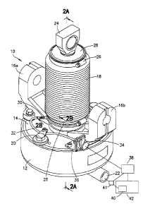
[0010] FIG. 1 is a front perspective view of a piston stroke sensor
arrangement for a brake
unit in accordance with one embodiment of the present disclosure;
[0011] FIG. 2A is a cross-sectional view of the brake unit of FIG. 1 along
line 2A-2A;
[0012] FIG. 213 is a cross-sectional view of the brake unit of FIG. 1 along
line 2B-2B;
[0013] FIG. 3 is a front perspective view of a piston tube in accordance with
one
embodiment of the present disclosure;
[00141 FIG. 4 is a side view of the piston tube of FIG. 3;
[0015] FIG. 5 is a sectional view depicting a proximity sensor and piston tube
in a non-
applied position in accordance with the present disclosure;
[0016] FIG. 6 is a sectional view of the proximity sensor and piston tube of
FIG. 5 in an
applied position;
[0017] FIG. 7 is a sectional view of the proximity sensor and piston tube of
FIG. 5 in an
over-stroke position; and
3
CA 02958895 2017-02-21
WO 2016/040430 PCT/US2015/049109
[0018] FIG. 8 is a side view of a piston tube in accordance with another
embodiment of the
present disclosure.
DESCRIPTION OF THE DISCLOSURE
[0019] For purposes of the description hereinafter, spatial orientation
terms, as used, shall
relate to the referenced embodiment as it is oriented in the accompanying
drawings, figures, or
otherwise described in the following detailed description. However, it is to
be understood that
the embodiments described hereinafter may assume many alternative variations
and
configurations. It is also to be understood that the specific components,
devices, features, and
operational sequences illustrated in the accompanying drawings, figures, or
otherwise
described herein are simply exemplary and should not be considered as
limiting.
[0020] The present disclosure is directed to, in general, a piston stroke
sensor arrangement
for a brake unit and, in particular, to a piston stroke sensor arrangement for
a disc brake unit
including a proximity sensor. Certain preferred and non-limiting embodiments
of the
components of the piston stroke sensor arrangement are illustrated in FIGS. 1-
8.
[0021] With reference to FIGS. 1-2B, a brake unit 10 is shown. In one
embodiment, the
brake unit 10 may be a part of a disc brake unit commonly used on railway
vehicles. It is to be
understood, however, that alternative types of brake units may be used,
including disc brake
units used in conjunction with bicycles, cars, buses, and other types of
vehicles that use brake
discs for effecting a braking force to a wheel. The brake unit 10 includes a
cylinder 12, an
anchor flange 14, first and second extension members 16a, 16b, and bellows 18.
The cylinder
12 and anchor flange 14 are secured to one another using a retaining ring 21
and a plurality of
fasteners 20. As shown in FIG. 2A, the retaining ring 21 is positioned between
the cylinder 12
and anchor flange 14 and the fasteners 20 lock the cylinder 12 and anchor
flange 14 in a secure
connection. An inlet 22 extends outwardly from the cylinder 12 and is
configured to supply
pressurized fluid from a fluid source 40 on a railway vehicle 42 to the brake
unit 10. An air
pressure indicator 41 may be positioned in fluid communication between the
fluid source 40
and the inlet 22 to measure the air pressure being supplied to the brake unit
10. In one
embodiment, the air pressure indicator 41 may be a pressure transducer. The
extension
members 16a, 16b are configured for connection to a caliper assembly (not
shown) of a disc
brake unit (not shown).
[0022] A proximity sensor 30 may be inserted through an opening defined in the
anchor
flange 14. The proximity sensor 30 may be used to detect the presence of
nearby objects and,
in particular, metallic objects without any physical contact with the objects.
The proximity
4
CA 02958895 2017-02-21
WO 2016/040430 PCT/US2015/049109
sensor 30 emits a detection signal S and identifies changes in the return
signal. Depending on
the value of the return signal and the air pressure being supplied to the
brake unit 10, a
notification device 38 determines the position of the target object. Many
different types of
proximity sensors may be used with the brake unit 10, including a capacitive
displacement
sensor, an optical sensor, an eddy-current sensor, an inductive sensor, a
laser sensor, a magnetic
sensor, a radar sensor, a sonar sensor, or an ultrasonic sensor, among others.
In one preferred
embodiment, an inductive proximity sensor is used. The proximity sensor 30 may
be cylindrical
in shape and is held in the anchor flange 14. It is also to be understood that
the proximity sensor
30 may have a trapezoidal, triangular, rectangular, or oval cross-sectional
shape. The proximity
sensor 30 may be threaded into the anchor Flange 14 with a lock nut (not
shown) used to secure
the proximity sensor 30 in place. The proximity sensor 30 may also be
installed using a friction
fit, but it is also contemplated that the proximity sensor 30 may be installed
using fasteners and
a flange or an adhesive. A cable 32 connects the proximity sensor 30 to a
connector 34. The
connector 34 is secured to the anchor flange 14 by a flange 36. The proximity
sensor 30 sends
the positional output information to the notification device 38 via the
connector 34. The air
pressure indicator 41 may also be in communication with the notification
device 38 to send air
pressure information to the notification device 38. The notification device 38
inay be an
indicator panel provided directly on the brake unit 10, a remote handheld unit
held by an
operator of the railway vehicle, a control panel of the railway vehicle, or a
control panel and/or
a central processing unit (CPU) provided in a railway monitoring station. It
is to be understood
that the connector 34 may send the signal information through a wired
connection or remotely.
The connector 34 may be connected to a remote signal emitting device (not
shown) or hard-
wired into a control panel and/or CPU.
100231 As shown in FIGS. 2A and 2B, the brake unit 10 houses a piston assembly
configured
to apply a braking force to the brake disc of a railway vehicle. As discussed
hereinabove, a
spindle head 24 may be connected to a caliper assembly that applies a braking
force to the
brake disc of the railway vehicle. The spindle head 24 may be threadedly
secured to the spindle
44 that is housed within the brake unit 10. The spindle 44 is movable along a
longitudinal axis
L of the brake unit 10. The bellows 18 may extend from the anchor flange 14 to
a spindle cover
28. The bellows 18 are secured to the brake unit 10 with clamp rings 26. ([is
to be understood
that the bellows 18 may he secured using other methods, such as adhesives,
fasteners, cable
ties, or welding. The spindle cover 28 may he provided on one end of the
spindle 44 near the
spindle head 24. As shown in FIG. 2A, the spindle cover 28 may be retained
between the
spindle head 24 and a spindle 44,
CA 02958895 2017-02-21
WO 2016/040430 PCT/US2015/049109
[0024] A collet support 46 is also provided in the brake unit 10. One end of
the collet support
46 encircles the spindle 44 and an opposing end of the collet support 46 is
connected to an end
of the anchor flange 24. The collet support 46 and the anchor flange 14
include correspondingly
threaded ends that are connected to one another. A biasing member 48 is
positioned in one end
of the collet support 46. A first collet 50 is also positioned in the collet
support 46 and is
positioned around the spindle 44. As the biasing member 48 is compressed by
the first collet
50, the biasing member 48 creates a biasing force against the first collet 50.
[0025] A second collet 52 is positioned around a lower portion of the spindle
44 and is
provided inside of a piston tube 54 .of the brake unit 10. The piston tube 54
effects the
movement of the second collet 52 during operation of the brake unit 10. The
proximity sensor
30 is positioned in the anchor flange 14 adjacent the piston tube 54.
[0026] A groove 56 is defined in the outer surface of the piston tube 54. The
groove 56 may
be a cut or depression formed in the piston tube 54., The groove 56 may extend
around the
entire outer circumferential surface of the piston tube 54. The groove 56 may
be defined on the
piston tube 54 adjacent the position or the proximity sensor 30 provided in
the anchor flange
14. The groove 56 may be defined around the outer surface of the piston tube
54 because the
piston tube 54 may rotate during operation of the brake unit 10. Regardless of
the angular
orientation of the piston tube 54 relative to the proximity sensor 30, the
proximity sensor 30 is
capable of taking a positional reading of the piston tube 54. It is also to be
understood that
instead of using the groove 56, a protrusion 57 may extend from the outer
circumferential
surface of the piston tube 54 (see FIG. 8). The protrusion 57 may be squared
to ensure an
accurate reading from the proximity sensor 30. Additional details regarding
the groove 56 are
provided herei nhe low.
[0027] Although the groove 56 is used with the piston tube 54, it is also
contemplated that a
hole may be provided in the piston tube 54 instead. Unlike the piston tube 54
of the brake unit
10, which may experience rotational movement during operation of the brake
unit 10, some
piston tubes may move in only a linear direction without rotational movement.
Since the piston
tube may not rotate during this operation, it is unnecessary to provide a
groove around the
entire outer circumferential surface of the piston tube. Therefore, a hole or
plurality of holes
may be drilled into a portion of the linear piston tube adjacent the proximity
sensor.
[0028] The cylinder 12 of the brake unit 10 defines a first cavity 58 and a
second cavity 59
therein and houses a biasing member 60 and a piston 62. 'the biasing member 60
may be
provided in the second cavity 59. The piston tube 54 and the piston 62 may be
welded together.
During operation of the brake unit 10, pressurized fluid is provided to the
first cavity 58 via
6
CA 02958895 2017-02-21
WO 2016/040430
PC1'/US2015/049109
inlet 22. The pressurized fluid acts against one side of the piston 62,
thereby compressing the
biasing member 60. As the biasing member 60 is compressed, a biasing force is
created against
the piston 62. As the piston 62 is moved further into the brake unit 10, the
piston 62 and the
piston tube 54 move upward along the longitudinal axis L of the brake unit 10.
The piston tube
54 moves towards and contacts the second collet 52. As the piston tube 54
moves upward, the
second collet 52 begins to grip the spindle 44 to move the spindle 44 upward
in the brake unit
10. The spindle 44 is moved along the longitudinal axis L of the brake unit
10, thereby moving
the spindle head 24 further out of the brake unit 10. As the spindle head 24
is moved further
out of the brake unit 10, a pivoting force is applied to the caliper assembly
(not shown), which
applies pressure to the brake discs of the railway vehicle via the brake pads.
During this
movement, the piston tube 54 moves within the anchor flange 14 along the
longitudinal axis L
of the brake unit 10 relative to the proximity sensor 30.
[0029] With reference to FIGS. 3 and 4. a more detailed description of the
groove 56 of the
piston tube 54 is provided. As shown, the groove 56 is defined in the piston
tube 54 and extends
around the outer circumferential surface of the piston tube 54. The groove 56
may be provided
on the entire outer circumferential surface of the piston tube 54 or only a
portion of the outer
circumferential surface of the piston tube 54. A leading edge 64 of the groove
56 and a trailing
edge 66 of the groove 56 are provided on the piston tube 54. The leading edge
64 of the groove
56 is positioned closer to the spindle head 24, and the trailing edge 66 of
the groove 56 is
positioned closer to the cylinder 12 (see FIG. 2A).
[0030] With reference to FIGS. 2a, 2b, and 5-7, a description of a method of
determining
the position of a piston in a brake unit is provided. Upon activation of the
proximity sensor 30,
a detection signal S is emitted from the proximity sensor 30. As described
above, the detection
signal S may be any type of feedback signal, including sonar, radar, laser,
magnetic, or any
other electronic signal. In one embodiment, the proximity sensor 30 is an
inductive proximity
sensor 30 that is configured to detect the presence of metallic objects, such
as the piston tube
54, via the use of a magnetic field. The proximity sensor 30 emits a detection
signal S
configured to determine the location of the piston 62 and piston tube 54
within the brake unit
based on the position of the piston tube 54 relative to the detection signal S
emitted from
the proximity sensor 30 and the amount of air pressure provided to the brake
unit 10. As shown
in FIGS. 1, 2A, and 5, when the piston tube 54 is positioned at a non-applied
position, the
detection signal S contacts the outer circumferential surface of the piston
tube 54. In one
embodiment, the detection signal S detects metal on the piston tube 54. Based
on the detection
of metal, the detection signal S relays positional output information back to
the notification
7
CA 02958895 2017-02-21
=
WO 2016/040430 PCT/US2015/049109
device 38 that the proximity sensor 30 is detecting the presence of a metallic
object. The air
pressure indicator 41 will also send air pressure information to the
notification device 38. In a
non-applied position of the brake unit 10, the proximity sensor 30 will detect
a metallic object
and the air pressure indicator 41 will indicate no air pressure being supplied
to the brake unit
10. The notification device 38 may then activate an indicator light or alert
signal that the brake
unit 10 is not applied.
[00311 As the brake unit 10 is applied, the piston 62 and piston tube 54 are
moved along the
longitudinal axis L of the brake unit 10. As shown in FIGS. 1, 2A, and 6, when
the brake unit
is applied, the leading edge 64 of the groove 56 is moved past the detection
signal S and the
groove 56 will align with the detection signal S emitted from the proximity
sensor 30. The
detection signal S detects the absence of metal in, the groove 56 and provides
this positional
output information to the notification device 38. The air pressure indicator
41 will also send air
pressure information to the notification device 38 indicating that air
pressure is being provided
to the brake unit 10. Due to the absence of metal and the supply of air
pressure to the brake
unit 10, the notification device 38 identifies that the brake unit 10 is in an
applied position. As
will be understood by one of skill in the art, the groove 56 may be cut to the
appropriate depth
and width so when the piston tube 54 is in the non-applied position, the
proximity sensor 30
detects metal on the piston tube 54 and, when the piston tube 54 is in the
applied position, the
proximity sensor 30 detects the absence of metal on the piston tube 54. It is
to he understood
that the proximity sensor 30 may not be configured to detect metal. Instead,
the proximity
sensor 30 may be configured to detect a solid object, such as the piston tulle
54, and the absence
of a solid object, such as tile groove 56.
[00321 As shown in FIGS. 1, 2A, and 7, when the brake unit 10 is over-stroked,
the leading
edge 64 and Hating edge 66 of the groove 56 are moved past the detection
signal S towards
the spindle head 24. During operation, the brake unit 10 may become over-
stroked due to a loss
of brake pads (not shown) or an internal failure in the brake unit 10. This
situation can cause
the piston tube 54 to be pushed past the desired position into an over-stroke
position. It is
beneficial to the operator of the vehicle to be aware of this situation so
repairs and maintenance
may be made to the appropriate structure of the brake unit 10. As the trailing
edge 66 moves
past the detection signal S, the proximity sensor 30 will again detect the
metal of the piston
tube 54 and will send this positional output information back to the
notification device 38. The
air pressure indicator 41 will send air pressure information to the
notification device 38
indicating that air pressure is being supplied to the brake unit 10. Based on
the proximity sensor
30 detecting a metallic object and the air pressure indicator 41 indicating
that air pressure is
8
CA 02958895 2017-02-21
WO 2016/040430 PCT/US2015/049109
being applied, the notification device 38 may identify that the brake unit 10
is in an over-
stroked position.
[0033] As will be readily apparent to one of skill in the art, the position of
the piston tube 54
in the brake unit 10 may be determined by providing the protrusion 57 on the
piston tube 54.
This method is similar to that used with the groove 56 on the piston tube 54.
When the brake
unit 10 is applied, the detection signal S emitted from the proximity sensor
30 may be directed
towards the protrusion 57 on the piston tube 54. When the brake unit 10 is not
applied, the
detection signal S emitted from the proximity sensor 30 may not be directed
towards the
protrusion 57 on the piston tube 54. The detection signal S may be directed
towards another
portion of the piston tube 54.
[0034] By using this piston stroke sensor arrangement on the brake unit, it
is no longer
necessary to inspect the brake units from underneath of or below the railway
vehicle. The brake
unit may be tested remotely or directly from the outside of the railway
vehicle without the need
for a pit or maintenance facility to inspect an in-board brake unit. This
arrangement also assists
in identifying an over-stroke condition for the brake unit 10 so that
corrective action may be
taken swiftly and promptly.
[0035] While an embodiment of a piston stroke sensor arrangement for a brake
unit is shown
in the accompanying figures and described hereinabove in detail, other
embodiments will be
apparent to, and readily made by, those skilled in the art without departing
from the scope and
spirit of the invention. Accordingly, the foregoing description is intended to
be illustrative
rather than restrictive. The invention described hereinabove is defined by the
appended claims
and all changes to the invention that fall within the meaning and the range of
equivalency of
the claims are to be embraced within their scope.
=
9