Note: Descriptions are shown in the official language in which they were submitted.
CA 02959036 2017-02-22
WO 2016/032909 1 PCT/US2015/046405
ELECTROSURGICAL INSTRUMENT WITH
SELECTIVE CONTROL OF ELECTRODE ACTIVITY
BACKGROUND OF THE INVENTION
1. The Field of the Invention
The present invention relates to electrosurgical instruments which provide for
selective increased ablative capability (e.g., increasing the size of the
sparking ablative
field (a discharge field) provided by the electrode) when desired, without
requiring any
increase in provided electrical power, as well as related methods of use.
2. The Relevant Technology
Electrosurgical procedures utilize an electrosurgical generator to supply
radio
frequency (RF) electrical power to an active electrode for ablating (i.e.,
vaporizing) and/or
coagulating tissue. An electrosurgical probe is generally formed of a metallic
conductor
surrounded by a dielectric insulator such as plastic, ceramic, or glass. The
electrode
remains exposed and provides the surface which coagulates or ablates adjacent
tissue.
During an electrosurgical procedure, the metal electrode is often immersed in
a conductive
fluid and is brought in contact with or in close proximity to the tissue
structure to be
ablated or coagulated. During a procedure, the electrode is typically
energized at a voltage
of a few hundred to a few thousand volts and at a frequency between 100 kHz to
over 4
MHz. The voltage induces a current in the conductive liquid and surrounding
tissue. The
most intense heating occurs in the region very close to the electrode where
the current
density is highest.
Depending on how the electrosurgical instrument is configured and how much
power is provided, the heat generated from the device can be used to coagulate
(e.g.,
cauterize) tissue or alternatively to ablate tissue. To cause ablation, the
electrode
generates enough heat to form gas bubbles around the electrode. The gas
bubbles have a
much higher resistance than tissue or saline, which causes the voltage across
the electrode
to increase. Given sufficient power, the electrode discharges (i.e., arcs).
The high voltage
current travels through the gas bubbles and creates a plasma discharge. This
phenomenon
visibly manifests itself in the conductive fluid medium as a sparking energy
field adjacent
the electrode. Where this occurs with the electrode close to the tissue, the
generated
plasma ablates the tissue.
Electrosurgical instruments can also be used for coagulating tissue. In
coagulation,
the current density at the electrode is configured to cause heating, but not
tissue
CA 02959036 2017-02-22
WO 2016/032909 2 PCT/US2015/046405
vaporization. The current density is generally lower than that provided during
ablation,
but is kept sufficiently high to cause proteins and/or other components of the
tissue to
agglomerate, thereby causing coagulation.
BRIEF SUMMARY OF THE INVENTION
The present invention is directed to electrosurgical instruments for ablating
tissue
at a surgical site of a patient in a surgical procedure. These instruments
typically have an
aspiration means through the electrode to draw bubbles and debris to keep the
field of
view optically clear. One of the effects of aspiration, whether desired or
not, is that fluid
can pass by or through the electrode and actively draw heat away from and cool
the
electrode. Recognizing the active cooling aspect of fluid aspiration, the
inventive
instruments advantageously provide for a selective increase or boost in
ablative capability
by temporarily decreasing or stopping fluid aspiration, effectively increasing
the size
and/or density of the ablative sparking energy field (the discharge field)
generated
adjacent to the electrode. This boosted ablation mode can be entered when
desired by a
practitioner without increasing the current density at the electrode, which
typically
requires increasing the electrical power provided to the electrode or reducing
the surface
area of the electrode. Instead, boosted ablation is provided by selectively
decreasing or
stopping the flow of cooling fluid through an aspiration lumen adjacent to the
electrode,
that opens in the electrode.
An exemplary electrosurgical instrument may include an elongate probe having a
handle portion, a distal end, and at least one electrode disposed at the
distal end of the
probe configured to perform ablation. An aspiration lumen may advantageously
be
disposed longitudinally through an interior of the elongate probe. The
aspiration lumen
may include an opening at the distal end of the probe so as to actively
aspirate fluid (e.g.,
saline, tissue, and gaseous bubbles at a surgical site). Aspirating fluid
through the lumen
also provides active cooling of the electrode and/or fluid immediately
adjacent to the
electrode, whether desired or not, which has the effect of decreasing the
strength of the
ablative discharge.
A user operable control component for selectively restricting aspiration to
the
aspiration lumen is provided and can be disposed on the handle portion of the
instrument
for convenience. Such a control component temporarily slows or stops active
suctioning
of fluid through the aspiration lumen opening, which reduces or stops the flow
of cooling
liquid past the electrode. The result is reduced cooling and increased heat
buildup at the
CA 02959036 2017-02-22
WO 2016/032909 3 PCT/US2015/046405
electrode surface and adjacent fluid, which causes increased vaporization of
water (e.g.,
more vapor bubbles) immediately adjacent to the electrode surface. This, in
turn,
increases electrical resistance at the electrode surface and surrounding fluid
and increases
sparking density at the electrode surface, which further increases heat at the
electrode
surface and surrounding tissue and boosts tissue ablation.
In many cases, the increase in sparking density at the electrode can visibly
increase
compared to the sparking density at the electrode when the instrument operates
in a
normal ablation mode, where active suctioning of fluid is provided. By way of
example,
the sparking density at the electrode when the electrosurgical instrument is
placed into
boosted ablation mode by decreasing or stopping aspiration of fluids through
the
aspiration lumen may increase by at least about 10% compared to the sparking
density at
the electrode during normal ablation mode (i.e., when aspiration of fluids is
at the normal
flow rate for the device or procedure). Preferably, the sparking density at
the electrode is
at least about 20% greater in boosted ablation mode, more preferably at least
about 35%
greater, and most preferably at least about 50% greater than when in normal
ablation
mode.
The heat produced adjacent to the electrode when in boosted ablation mode may
similarly increase and, in many cases, may cause an increase in water vapor
production as
a percentage of normal water vapor production than the increase in sparking
density. For
example, the volume of water vapor bubbles produced by the electrode in
boosted ablation
mode may increase by at least about 20% compared to the amount of water vapor
bubbles
produced by the electrode in normal ablation mode. Preferably, the volume of
water vapor
bubbles produced by the electrode is at least about 40% greater in boosted
ablation mode,
more preferably at least about 70% greater, and most preferably at least about
100%
greater than when in normal ablation mode.
Increased water vapor bubble production is often beneficial because the
increase in
heat and water vapor bubble production at the electrode correlates with the
rate of tissue
ablation. Accordingly, an increase in sparking density at the electrode,
coupled with an
increase in water vapor bubble production can correlate with an increase in
the rate of
tissue ablation. In some embodiments, the rate of tissue ablation in boosted
ablation mode
can be increased by at least about 10% compared to normal ablation mode.
Preferably the
rate of tissue ablation is increased by at least about 20%, more preferably by
at least about
CA 02959036 2017-02-22
WO 2016/032909 4 PCT/US2015/046405
35%, and most preferably by at least about 50% in boosted ablation mode
compared to
normal tissue ablation mode.
In one embodiment, controls (e.g., one or more buttons) may be provided on the
handle portion of the instrument for activating the electrode to operate in
normal ablation
mode and for selectively causing the electrode to operate in boosted ablation
mode. The
one or more controls may also cause the electrode to operate in coagulation
mode (e.g., by
reducing current density at the electrode to coagulate instead of ablate
tissue). In one
embodiment, decreasing or stopping the flow of aspirating fluid may cause the
electrode to
switch from coagulation mode to ablation mode. Because such controls (e.g.,
one or more
buttons) are disposed on the handle portion, they are easily accessible to the
practitioner's
thumb (or fingers) of the hand that grips the instrument, without requiring
the practitioner
to release or adjust his or her grip.
Upon selection of the boosted ablation mode, active cooling of the electrode
by
aspirating fluid past the electrode is temporarily decreased, stopped, or
simply not
initiated. As a result of the reduction in active cooling when a boosted
ablation mode is
selected, fluid and tissue adjacent to the electrode are rapidly heated,
providing a nearly
instantaneous boost to ablative capability provided by the instrument.
According to one
embodiment, a control can be configured to only place the device in boosted
ablation
mode while the control component (e.g., button) is depressed or otherwise
activated.
Release of the control advantageously restores the device to the normal
ablation mode
and/or a coagulation mode. Such boosted ablation may be visibly manifested as
an
ablative sparking energy field of increased density and/or size relative to
the density
and/or size of the sparking energy field when in normal ablation mode.
Another aspect is a method of using the disclosed electrosurgical devices.
Such
method may include providing an instrument as described above, activating a
control
component disposed on the handle portion to place the device in normal
ablation mode,
and selectively activating a control component to temporarily place the device
in boosted
ablation mode. During normal ablation mode, a desired amount of power is
supplied to the
electrode and a desired amount of aspirating fluid is aspirated through the
aspiration lumen
adjacent to the electrode. During boosted ablation mode, activation of a
control
temporarily decreases or stops aspiration of fluids through the aspiration
lumen, causing
increased heat, increased vapor production (e.g., water bubbles) adjacent to
the electrode,
increased sparking density, and even more heat at the electrode, which further
boosts the
CA 02959036 2017-02-22
WO 2016/032909 5 PCT/US2015/046405
rate of tissue ablation. In some cases, there will be a visible increase in
sparking density
and light intensity at the electrode.
Further features and advantages of the present invention will become apparent
to
those of ordinary skill in the art in view of the detailed description of
preferred
embodiments below.
BRIEF DESCRIPTION OF THE DRAWINGS
To further clarify the above and other advantages and features of the present
invention, a more particular description of the invention will be rendered by
reference to
specific embodiments thereof which are illustrated in the appended drawings.
It is
appreciated that these drawings depict only typical embodiments of the
invention and are
therefore not to be considered limiting of its scope. The invention will be
described and
explained with additional specificity and detail through the use of the
accompanying
drawings in which:
Figure 1 is a perspective view of an exemplary electrosurgical instrument
according to an embodiment of the present invention coupled to a radio
frequency
generator and an aspirator;
Figure lA is a perspective view similar to that of Figure 1, showing an
alternative
instrument configuration;
Figure 1B is a perspective view similar to that of Figure 1, showing another
alternative instrument configuration;
Figure 1C is a perspective view similar to that of Figure 1, showing yet
another
alternative instrument configuration;
Figure 1D is a perspective view similar to that of Figure 1, showing yet
another
alternative instrument configuration;
Figure lE is a perspective view similar to that of Figure 1, showing an
alternative
instrument configuration, with one or more of the control buttons on the
bottom surface of
the handle portion of the instrument;
Figure 2 is a close up view of the distal electrode end of the exemplary
electrosurgical instrument of Figure 1;
Figure 3A shows a cross-sectional view through the distal end of the exemplary
electrosurgical instrument of Figure 1;
Figure 3B shows a cross-sectional view through the distal end of another
exemplary electrosurgical instrument;
CA 02959036 2017-02-22
WO 2016/032909 6 PCT/US2015/046405
Figure 4A shows a cross-sectional schematic view of an exemplary spring loaded
button for providing the boosted ablation mode;
Figure 4B shows a cross-sectional schematic view of the spring loaded button
of
Figure 4A, but with the button depressed, so as to provide boosted ablation;
Figures 4C-4D show perspective views of an exemplary button and the
surrounding handle where the button is configured as a roller for providing
the boosted
ablation mode;
Figure 4E shows a cross-sectional schematic view of the exemplary roller
button of
Figure 4C-4D;
Figure 4F shows a cross-sectional schematic view of the roller button of
Figure
4C-4D, but with the roller advanced, so as to provide boosted ablation;
Figure 5 illustrates an exemplary operating room environment where
arthroscopic
surgery is being conducted on a knee of a patient, showing how the
practitioner guides and
manipulates an endoscopic instrument with one hand, and an electrosurgical
instrument
such as that of Figure 1 with the other hand, simultaneously;
Figure 6A shows a close up schematic view of the distal electrode end of an
exemplary electrosurgical instrument, positioned adjacent tissue to be
ablated, with active
cooling of the electrode;
Figure 6B shows a close up schematic view similar to that of Figure 6A, but
where
active cooling of the electrode has been temporarily decreased or halted,
providing a
boosted ablation mode with a larger and/or more intense ablative sparking
energy field
provided by the electrode;
Figure 7A shows a schematic view of the distal electrode end of an exemplary
electrosurgical instrument, schematically illustrating the energy field
generated during
operation in the normal ablation mode, with active cooling of the electrode;
and
Figure 7B shows a view similar to that of Figure 7A, illustrating how
temporarily
decreasing or halting cooling of the electrode causes the energy field to
become enlarged.
DETAILED DESCRIPTION
I. Introduction
The present disclosure is directed to electrosurgical instruments for
selectively
operating in normal and boosted ablation modes in ablative capability (e.g.,
by providing
increased sparking density at the electrode) without requiring an increase in
current
density at the electrode and related methods of use. For example, such an
instrument may
CA 02959036 2017-02-22
WO 2016/032909 7 PCT/US2015/046405
include an elongate probe having a handle portion and a distal end, at least
one electrode
disposed at a distal end of the elongate probe configured to perform ablation,
and an
aspiration lumen disposed within the elongate probe that opens at the distal
end of the
elongate probe so as to actively aspirate fluid adjacent the distal end of the
elongate probe
through the aspiration lumen opening and into the aspiration lumen while
aspiration is
applied to the aspiration lumen.
The instrument includes one or more user operable control components (e.g.,
buttons), disposed on the handle portion of the elongate probe. At least one
such control
component is configured to selectively restrict aspiration to the aspiration
lumen so as to
temporarily decrease or stop active suctioning of fluid, tissue debris and/or
vapor bubbles
through the aspiration lumen opening. Such functionality advantageously
provides an
ablative sparking energy field provided by the at least one electrode that is
more dense
and/or larger and/or more intense as compared to the sparking energy field
generated
while normal aspiration is applied. A boost in the rate of tissue ablation may
advantageously be achieved without increases the current density at the at
least one
electrode.
For example, during normal operation, where the button or other control
component which restricts aspiration is not activated, active cooling of the
electrode
occurs as irrigating saline or similar liquid is delivered to the site (e.g.,
from an adjacent
separate instrument, such as an endoscope) and actively aspirated through a
lumen
adjacent to the electrode. This irrigating saline, along with tissue debris,
bubbles and/or
other materials resulting from the procedure, are suctioned into the
aspiration lumen,
which may open through the electrode. As a result, under such operation,
saline
continuously passes by the electrode surfaces, providing active cooling of the
electrode
and adjacent fluids.
Upon activation of the button or other control component to provide a boost to
ablative capability, active cooling is temporarily decreased or suspended as
aspiration of
fluid is slowed or stopped. This causes any saline and other materials
adjacent the
electrode to quickly be heated. Because additional saline is not being
actively drawn
toward the electrode surfaces, materials in the immediate vicinity of the
electrode are more
quickly vaporized or ablated. Increasing the quantity of water vapor near the
electrode
surface increases electrical resistance, which causes even higher sparking
density when
operating the electrode at the same current density as in normal ablation
mode. As a
CA 02959036 2017-02-22
WO 2016/032909 8 PCT/US2015/046405
result, a more dense and/or larger and/or more intense ablative sparking
energy field is
generated, and tissue adjacent the electrode is much more quickly and
effectively ablated.
Even if active aspiration is not employed (e.g., by wall suction or
peristaltic pump) and
passive outflow is allowed, because of a positive pressure difference between
the fluid at
the electrode end of the lumen, some fluid flow may still occur (e.g., unless
the lumen is
completely blocked). For example, there may be about 30 to about 80, or about
50 to
about 80 mm Hg of a pressure differential between the electrode end of the
aspiration
lumen and the proximal end of the aspiration lumen.
It has been observed that the distal tip with the electrode can light up like
a
flamethrower or blow torch almost immediately after active cooling is slowed
or stopped.
This allows the practitioner to cut through or ablate tissue which proved to
be more
difficult under the previous otherwise similar conditions where fluid
aspiration actively
cools the electrode. Such increased ablative capability is made possible even
without
providing an increase in electrical power and/or current density to the
electrode and/or
without decreasing the electrode surface area. The practitioner may thus cut
through,
ablate and remove more difficult portions of tissue by actuating such a button
or other
control component. Following a burst of increased tissue ablation ability,
deactivation
(e.g., release) of the button may cause or permit fluid aspiration to resume,
which clears
away debris in the stream of irrigant drawn into the aspiration lumen opening
and actively
cools the electrode.
II. Exemplary Electrosurgical Instruments and Related Methods
Following are exemplary configurations that can be used in or as part of the
inventive apparatus and methods. Notwithstanding the following descriptions
relative to
how the illustrate user-operated control components may function in the
described
embodiments, it should be understood that the illustrated user-operable
buttons or other
control components can be modified to provide other functionalities as
desired. For
example, one, some, or all of the illustrated buttons and foot pedals (or
other control
components known in the art) can be configured to function as a toggle switch,
such as
activating a specified function when placed in a first position (or actuated a
first time) and
deactivating the function and/or providing a different function when placed in
a second
position (or actuated a second time). Alternatively, one, some, or all of the
illustrated
buttons and/or foot pedals can be configured so as to only activate a
specified function
when continuously actuated by the user, such as a safety switch or button that
only
CA 02959036 2017-02-22
WO 2016/032909 9 PCT/US2015/046405
activates an electrode or other function, such as reducing or cutting off
aspiration, when
depressed.
In some embodiments, aspiration can be initiated or stopped independently of
one
or more user-operated controls that operate the electrode features. In other
words, the
device can be continuously aspirating or not aspirating independently of how
or when a
user manipulates one or more controls to operate the electrode features. In
other
embodiments, aspiration can be initiated, stopped, or reduced using one, some,
or all of the
one or more user-operated controls that operate the electrode features.
In embodiments where continuous aspiration is provided independently of the
user-operated control components that operate the electrode features, a first
user-operated
control component can be actuated to deliver power to an ablation electrode
and place the
apparatus in normal ablation mode. A second user-operated control component
can be
actuated to deliver power to a coagulation electrode and place the apparatus
in coagulation
mode. A third user-operated control component can be actuated to place the
apparatus in
boosted ablation mode, with power being delivered to the ablation electrode
while
simultaneously reducing or cutting off aspiration. In some embodiments, at
least the third
user-operated control component can be a safety switch that only causes
boosted ablation
when continuously actuated by the user. Release of the third control component
can
automatically cease boosted ablation, e.g., by restoring aspiration and/or
cutting off power
to the ablation electrode. In some embodiments, the first and third user-
operated controls
can be safety switches so that the first user-operated control must be
continuously actuated
to place the apparatus in normal ablation mode and both the first and third
user-operated
controls must be continuously actuated to place the apparatus in boosted
ablation mode.
Depending on the device design and/or user selection, releasing or
deactivating the third
control to switch out of boosted ablation made may switch the apparatus back
to normal
ablation mode, switch the apparatus to coagulation mode, or cease all
electrode function,
with continued aspiration or cessation of aspiration.
In other embodiments, aspiration may be initiated, stopped, or reduced using
one,
some, or all of the one or more user-operated control components that operate
the
electrode features. In other words, the device may only begin or cease
aspiration when a
user manipulates one or more controls to operate the electrode features. By
way of
example, a first user-operated control component can be actuated to initiate
aspiration and
also deliver power to an ablation electrode to place the apparatus in normal
ablation mode.
CA 02959036 2017-02-22
WO 2016/032909 10 PCT/US2015/046405
A second user-operated control component can be actuated to initiate
aspiration and also
deliver power to a coagulation electrode to place the apparatus in coagulation
mode. A
third user-operated control component can place the apparatus in boosted
ablation mode
by delivering power to the ablation electrode and not initiating aspiration or
only initiating
partial aspiration. As above, at least the third user-operated control
component can be a
safety switch that only causes boosted ablation while being continuously
actuated by the
user. Release of the third control component can automatically stop boosted
ablation, e.g.,
by cutting off power to the ablation electrode and/or restoring aspiration if
the first user-
operated control component has been actuated (if a toggle switch) or is being
continuously
actuated (if a safety switch). Depending on the device design and/or user
selections,
switching the apparatus out of boosted ablation mode may switch it to normal
ablation
mode, switch it to coagulation mode, or cease all electrode function.
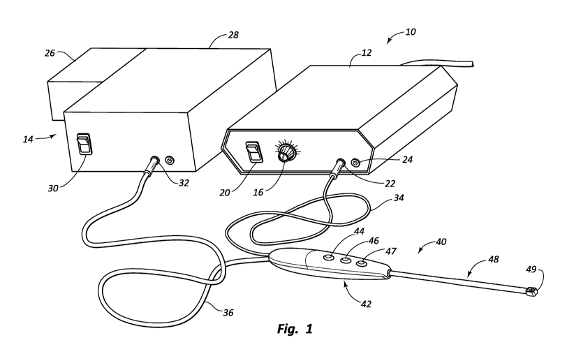
Figure 1 illustrates an exemplary electrosurgical system according to some
embodiments of the invention. The electrosurgical system 10 includes an
electrosurgical
instrument 40 that is electrically coupled to an electrosurgical generator 12
and an
aspirator 14. Aspirator 14 can be configured to provide or cease aspiration
independently
of user-operated switches or other control components for controlling
electrode function.
Alternatively, aspirator 14 can be configured to provide or cease aspiration
in conjunction
with user-operated switches or other control components for controlling
electrode
function.
Electrosurgical generator 12 may be configured to generate radio frequency
("RF")
wave forms. Generator 12 can generate power useful for ablating tissue and
optionally
coagulating tissue. In one embodiment, generator 12 may include standard
components,
such as dial 16 for controlling the frequency and/or amplitude of the RF
energy, a switch
20 for turning the generator on and off, and an electrical port 22 for
connecting the
electrosurgical instrument 40. Generator 12 may also include a port 24 for
connecting an
electrical ground or a return electrode. It will be appreciated that generator
12 can be
designed for use with both bipolar and monopolar electrosurgical instruments.
Bipolar
instruments include a return electrode on the electrosurgical instrument
itself (e.g., at the
distal end thereof). Monopolar instruments may not include a return electrode,
as the
return electrode may be provided separately. Generator 12 may be designed to
operate at
constant electrical current through the electrode and/or at constant power in
order to avoid
unwanted bursts of electrical current and/or power through the patient.
CA 02959036 2017-02-22
WO 2016/032909 11 PCT/US2015/046405
Aspirator 14 may include a pump 26, a reservoir 28, an on/off switch 30, and
an
aspirator port 32. Pump 26 provides negative pressure for aspirating fluids,
gasses, and
debris through electrosurgical instrument 40. Aspirated fluids and debris can
be
temporarily stored in reservoir 28. In another embodiment, electrosurgical
instrument 40
may be connected to wall suction. When using wall suction, canisters or other
reservoirs
may be placed in the suction line to collect aspirated debris and fluids.
Those skilled in
the art will recognize that many different configurations of generator 12 and
aspirator 14
can be used in the present invention.
Electrosurgical instrument 40 is depicted as an elongate probe and includes a
power cord 34 for providing electrical power to instrument 40 from generator
12 through
electrical port 22. Extension tubing 36 may provide a fluid connection between
instrument 40 and aspirator 14. Electrosurgical instrument 40 may include a
handle
portion 42 and a distal end portion 48. In one embodiment, handle portion 42
provides an
enlarged, easily grippable handle for instrument 40. Distal end portion 48 of
instrument
40 may include an electrode head 49, which includes one or more electrodes, as
well as an
opening for an aspiration lumen.
Instrument 40 may be configured to only ablate tissue or, alternatively, so as
to
selectively coagulate or ablate tissue. Handle portion 42 is shown as
including three
buttons 44, 46, and 47, or other control components that may be easily
operated by the
practitioner, without requiring the practitioner to release his or her grip on
handle portion
42. Thus, buttons 44, 46, and 47 may be easily and conveniently manipulated
during a
surgical procedure (e.g., by reaching and pressing with a thumb of the
gripping hand).
Two buttons (e.g., 44 and 46) may allow the practitioner to select or switch
between
coagulation mode (e.g., button 44) and ablation mode (e.g., button 46). Button
47 may
activate the boosted ablation mode by temporarily restricting aspiration of
fluids through
the lumen and active cooling of electrode head 49.
Providing controls for selecting between coagulation mode, ablation mode, and
boosted ablation mode on proximal handle portion 42 is advantageous, as during
a typical
arthroscopic or similar procedure, the practitioner grips and manipulates an
instrument
such as 40 in one hand, and another instrument (e.g., an endoscope) in the
other hand (e.g.,
see Figure 5). Thus, with both hands occupied, it can otherwise be difficult
and
impractical to manipulate controls that are disposed elsewhere (e.g., on
generator 12,
aspirator 14, etc.). Placement of the controls on handle portion 42 is
particularly
CA 02959036 2017-02-22
WO 2016/032909 12 PCT/US2015/046405
beneficial as this provides the practitioner with greater flexibility in the
mode of operation,
and specific operational characteristics provided by instrument 40, without
requiring help
from an assistant, release of a hand from handle portion 42, etc.
In an embodiment, as illustrated, the button or other control component 47 for
boosting ablative capability may be disposed adjacent to the control component
46 for
selecting the ablation mode (e.g., and not adjacent an optional control
component 44 for
selecting a coagulation mode, where a coagulation mode is provided). Such
placement
may be beneficial, as the practitioner may select the ablation mode by
pressing button 46
(e.g., with the thumb), and if insufficient ablative capability is being
provided, the
practitioner may slide the thumb upwards to button 47, depressing button 47 so
as to
temporarily deliver increased ablative capability. Because button 47 is in
sufficiently
close proximity to button 46 (e.g., no buttons disposed therebetween), this
can be
accomplished using the thumb, without the practitioner having to release his
or her grip of
the proximal handle portion 42.
One, some, or all of buttons 44, 46, and 47 may be toggle switches, safety
switches, or combinations of toggle and safety switches. In some embodiments,
only
button 47 is a safety switch and buttons 44 and 46 are toggle switches such
that boosted
ablation only occurs while button 47 is continuously actuated (e.g.,
depressed). In other
embodiments, button 46 is also a safety switch such that normal ablation only
occurs while
button 46 is actuated (e.g., depressed). In some cases, actuating button 47
results in
boosted ablation. In other cases, buttons 46 and 47 must be actuated
simultaneously to
provide boosted ablation.
In some embodiments, such as where buttons 46 and 47 are both safety switches,
the practitioner may be required to continuously depress button 46 for normal
ablation and
both buttons 46, 47 simultaneously for boosted ablation. In another
embodiment, where
button 46 is a toggle switch and has already been actuated, actuating button
47 will permit
the instrument to continue operating in ablation mode while also cutting off
or restricting
aspiration to provide boosted ablation. A configuration requiring simultaneous
depression
of buttons 46, 47 for boosted ablation may be preferred for safety reasons
(e.g., upon
release of any given button, the functionality previously provided by
depression of that
button ceases).
In some embodiments, one or more of the control buttons may be disposed on
another surface of the instrument 40. For example, buttons 44, 46, and 47 are
shown in
CA 02959036 2017-02-22
WO 2016/032909 13 PCT/US2015/046405
Figure 1 as being disposed on a top surface of handle portion 42, although in
another
embodiment, one or more of buttons 44, 46, or 47 could be disposed on a bottom
surface
of handle portion 42. For example, button 47 could be disposed on the bottom
side of
handle portion 42, allowing the practitioner to depress button 46 (or 44) with
the thumb on
the top of handle portion 42, while button 47 could be depressed with a finger
of the same
hand. This may be particularly beneficial where the instrument may require
simultaneous
pressing of the ablation button (e.g., 46) and the ablation boost button
(e.g., 47) to operate
in boosted ablation mode. Such an embodiment is shown in Figure 1E.
In another embodiment, only two buttons (e.g., 44 and 46) may be provided,
where
button 46 may serve both to select normal ablation when actuated a first time
and initiate
boosted ablation when actuated a second time. Figure lA illustrates such an
embodiment.
For example, upon first pressing button 46, a "normal" ablation mode may be
selected. In
order to provide increased ablative capability, the practitioner may press
button 46 again.
In an embodiment, button 46 may be held down so long as the increase in
ablative
capability is desired. Release of button 46 (or pressing it a third time) may
either restore
the device to normal ablation mode by resuming fluid aspiration and active
cooling of the
electrode, or it may cease ablation entirely until actuated again. The control
components
could also be configured to cancel the boosted ablation mode by pressing one
of the other
buttons (e.g., button 44).
While the user operable control components are illustrated as buttons 44, 46,
and
47, it will be appreciated that any suitable user operable control components,
including but
not limited to buttons, switches, a touch screen, etc. may be suitable for
use. The user may
select between two basic operational modes with control components 44 and 46,
and may
select a boosted ablation mode by actuating control component 47 (e.g., when
in the
ablation mode). The control components 44 and 46 can be any type of mechanical
or
electrical input device which upon actuation causes the desired change in
delivery of
electrical power, and/or a change in the amount of active electrode surface
area.
In an embodiment, the control component 47 for providing boosted ablation may
be configured to simultaneously begin delivery of power to the ablation
electrode 50 and
cut off or reduce aspiration. Thus the electrode may be activated
independently and
simultaneously by button 47 (while button 46 may independently provide for
activation of
electrode 50 for the normal ablation mode). In such an embodiment, when button
47 is no
CA 02959036 2017-02-22
WO 2016/032909 14 PCT/US2015/046405
longer actuated, not only may aspiration be restored, but electrical power to
the electrode
may also be cut off.
For safety reasons, the preferred configuration for at least button 47 may be
a
spring loaded safety button or otherwise default to an unactivated or
deactivated condition,
so that power is only delivered to the electrode when the button is actively
depressed or
otherwise continuously actuated. Figures 4A-4B, described in further detail
below, show
an exemplary spring activated button 47. It will be appreciated that any of
the buttons or
other control components may be spring loaded or similarly configured to shut
off when
not actively depressed (or actuated). For example, depression of spring loaded
button 47
may complete an electrical circuit providing electrical power to the
electrode. Depression
of spring loaded button 47 may also cut off or at least reduce aspiration.
Control component 47 may similarly be any type of mechanical, electrical, or
other
input device which upon actuation selectively decreases or cuts off aspiration
to aspiration
lumen opening 52 so as to slow or suspend fluid aspiration and active cooling
of electrode
50 so long as control component 47 is actuated. For example, activation of
button 47 may
send an electrical or other signal to aspirator 14 instructing it to decrease
or cut off
aspiration. In another embodiment, activation of button 47 may mechanically
occlude or
close off aspiration lumen 56 (e.g., through a roller, a valve, etc.),
preventing suction from
being applied over opening 52. In any case, when active cooling is reduced or
eliminated,
electrode 50 provides significantly greater ablative capability manifest as an
ablative
sparking energy field that is larger and/or more intense while so actuated.
For example, it
has been observed that the electrode distal end of the instrument nearly
immediately lights
up like a flamethrower or blow torch, so long as such active cooling is
suspended. Upon
release of control component 47 or other cancelling of the boosted ablation
mode, fluid
flow and active cooling are restored, returning the device to normal ablation
mode.
It will be appreciated that a device which does not include a coagulation mode
may
be employed, e.g., including a button 46 to activate ablation, and another
button 47 to
enter a boosted ablation mode (Figure 1B). Similarly, as described above, it
will be
apparent that a single button may control both the ability to enter the normal
ablation
mode (where fluid flow and active cooling are provided) and a boosted ablation
mode
(where fluid flow and associated cooling are temporarily decreased or
suspended). Such a
button may also provide for a coagulation mode, if desired, such as by
reducing power to
the electrode. For example, such a single button embodiment is shown in Figure
1C,
CA 02959036 2017-02-22
WO 2016/032909 15 PCT/US2015/046405
otherwise similar to Figure 1, but without buttons 44 and 47. Upon first
pressing button
46, the ablation mode may be activated. In order to provide increased ablative
capability,
the practitioner may press button 46 again. In an embodiment, button 46 may be
held
down so long as the increase in ablative capability is desired. Release of
button 46 (or
pressing it a third time) may resume fluid flow, active cooling, and normal
ablation by the
electrode.
Where the single button is configured to provide coagulation as well, pressing
it
(e.g., button 46 of Figure 1C) a first time may select coagulation, pressing
it a second time
may select ablation, and pressing it a third time may select boosted ablation.
A display 45
may also be provided to provide an indicator of which mode is currently
selected, e.g.,
displaying C for coagulation, A for ablation and BA or some other indicator
designating
the boosted ablation mode. It will be apparent that any indicator scheme may
be
employed, and that such a display may be included with any of the other device
configurations disclosed herein.
In another alternative, one or more control components (e.g., a button) may be
configured to switch into an ablation mode from a coagulation mode by
decreasing or
cutting off aspiration. For example, in a coagulation mode, upon restricting
or cutting off
active suction of cooling saline, the energy field generated by the electrode
may then be
sufficiently intense to provide ablation, rather than coagulation. Thus, a
user may operate
the device in coagulation mode and, by pressing the button which decreases or
cuts off
aspiration and associated cooling, may enter an ablation mode without
increasing the
provided electrical power.
It is not necessary that the controls for switching between a coagulation mode
and
the normal ablation mode be configured as button(s) positioned on the handle
of the
instrument. For example, in another embodiment, a foot pedal may be provided
which
may allow selection of the coagulation mode or the ablation mode. Such an
embodiment
may include a single button or other user operable control component 47
disposed on the
handle portion for restricting aspiration, and providing a boosted mode of
operation. As
described herein, such a boost may be selected and provided whether in a
coagulation
mode or an ablation mode, in any of the embodiments described herein. Figure
1D
illustrates a system as described above including a single button 47 (e.g.,
similar to Figure
1C), but also including foot pedals 44' and 46' for selecting a coagulation
mode (e.g., pedal
44') or a normal ablation mode (e.g., pedal 46'). In another embodiment,
selection of the
CA 02959036 2017-02-22
WO 2016/032909 16 PCT/US2015/046405
coagulation or normal ablation mode could be achieved with a switch 18 or
similar control
component (e.g., on generator 12). Of course, such a switch may be less
preferred, as it is
not readily accessible to the practitioner without a "third" hand.
Figures 2 and 3A illustrate a close up view and cross-sectional view,
respectively
of an exemplary embodiment of an electrode configuration. As illustrated,
instrument 40
may include an electrode 50 on distal end portion 48, which electrode 50 is
exposed so as
to allow its contact with tissue to be coagulated or ablated. Electrode 50 may
be a
conductive element such as a metal or other suitable material for conducting
an electrical
current. Electrode 50 may be electrically insulated from the remainder of
instrument 40
by insulating material 54 (e.g., a ceramic). Electrical power may be delivered
to electrode
50 from generator 12 and cord 34 through appropriate electrical traces or
other wiring (not
shown).
As seen in Figures 2-3A, in an embodiment, electrode 50 may be configured so
as
to include one or more sharp angled edges (e.g., as opposed to smoothly curved
edges),
e.g., adjacent opening 52 of aspiration lumen 56. In an embodiment, the
opening 52 of
aspiration lumen 56 may be disposed through electrode 50, and may be other
than circular,
oval, or other rounded shape. For example, the opening may include a cross-
section that is
polygonal in shape, so as to define one or more sharp edges in adjacent
electrode 50, as
perhaps best seen in Figure 2. For example, Figure 2 shows a cross-shaped
geometry for
opening 52 of aspiration lumen 56. One or more bumps or protrusions 58
extending
upwardly from electrode surface 50 may be provided, as seen in Figure 2.
Figure 3A
shows a cross-sectional schematic view through a portion of instrument 40,
illustrating
protrusions 58, as well as opening 52 of aspiration lumen 56. Aspiration lumen
56 may
extend within instrument 40, with opening 52 being positioned within electrode
50.
Aspiration lumen 56 can be used with aspirator 14 (Figure 1) to withdraw
debris and fluids
from the surgical site during ablation and/or coagulation.
Electrode 50 may be configured to provide ablation when instrument 40 is in
the
ablation mode. Electrodes configured for ablation may have a relatively small
surface
area, so that the power provided by generator 12 to electrode 50 is sufficient
to create a
plasma in the aqueous medium. In an embodiment instrument 40 may include a
power
output of from about 150 W to 400 W, more preferably about 200 W to 400 W.
Applicable regulatory requirements within the U.S. limit power delivery of
such
electrosurgical instruments to no more than 400 W. For a power rating of 400
W, the
CA 02959036 2017-02-22
WO 2016/032909 17 PCT/US2015/046405
active surface area can be in a range from about 3 mm2 to about 30 mm2, more
preferably
about 5 mm2 to about 25 mm2, and most preferably about 7 mm2 to about 20 mm2.
Although Figure 2 illustrates a single active electrode, it will be
appreciated that
more than one electrode may be provided (e.g., electrically isolated from one
another).
For example, a separate electrode may be provided, which may or may not be
operated in
combination with electrode 50 for increased electrode area when in a
coagulation mode.
In addition, in a bipolar instrument, a return electrode may be provided on
distal end 48.
By way of example, the inventor's U.S. Patent No. 8,394,088, discloses further
details of
such systems. The above referenced patent is herein incorporated by reference
in its
entirety.
Electrode 50 is shown as providing a continuous surface area. In an
alternative
configuration, the one or more electrodes may comprise a plurality of distinct
surface
areas each separated by an insulating material. An example of such an
electrode is shown
in U.S. Patent No. 8,394,088, incorporated by reference above.
Instrument 40 may switch between ablation and coagulation modes by changing
the amount of power provided to electrode 50, by activating an additional
electrode to
increase surface area for a coagulation mode (e.g., at the same power), or
both. For
example, when switching from an ablation mode to a coagulation mode, the power
provided to the electrode(s) may be decreased, and/or the surface area of
active
electrode(s) may be increased. In any case, such selection results in a
decrease in power
density per electrode surface area. When selecting the ablation mode, the
power density
per electrode surface area is sufficiently high to form a plasma, while in the
coagulation
mode, the power density per electrode surface area is lower, and may not
result in plasma
formation, but may be sufficient to coagulate tissue adjacent the
electrode(s). Of course,
in some embodiments, the instrument may not provide a coagulation mode.
When in the ablation mode and selecting the boosted ablation mode (so as to
move
from one to the other), no increase in delivered electrical power may be
associated with
the change. For example, a given amount of power up to 400 Watts may be
provided to
the electrode when in the ablation mode, and the same amount of electrical
power may be
delivered when switching to the boosted ablation mode. Even so, as described
herein, a
more dense ablative sparking energy field is provided. In an embodiment, the
ablative
sparking energy field may increase in density by at least about 10%, at least
about 20%, at
CA 02959036 2017-02-22
WO 2016/032909 18 PCT/US2015/046405
least about 35%, at least about 50%, at least about 75%, at least about 100%,
at least about
150%, or at least about 200%.
Figure 3B illustrates a configuration similar to that of Figure 3A, but in
which the
opening 52' into lumen 56 is smaller than the underlying dimension of lumen
56. Such an
embodiment may aid in preventing plugging of lumen 56, as if a piece of debris
is
sufficiently large to pass through opening 52', it will easily pass through
lumen 56 to
storage reservoir 28. For example, opening 52' may have a width or diameter
dimension
(for circular openings) that is smaller than the width or diameter of lumen
56, adjacent
opening 52'. Of course, other embodiments are also possible, where the width
or diameter
of the opening is greater than the width or diameter of the lumen at a
location adjacent the
opening (e.g., Figure 3A shows such an embodiment).
Figures 4A and 4B illustrate schematic views of button 47, which may be spring
loaded with spring 51 so as to default or be biased to an unselected
configuration. Figure
4A shows button 47 in the default, unselected configuration. Figure 4B shows
button 47
in the depressed configuration (e.g., with thumb 53). The practitioner may
depress and
hold down button 47 so long as the boosted ablation mode is desired. While
depressed,
aspiration to opening 52 may be temporarily decreased or cut off to
temporarily slow or
suspend the flow of cooling irrigant fluid adjacent to electrode 50, providing
the desired
increased ablative capability. Once the spring loaded button 47 is released,
normal
aspiration, fluid flow, and associated cooling of electrode 50 may resume.
In another embodiment, spring loaded button 47 may include 2-stage function,
by
which button 47 locks in a depressed condition once pressed, and by which the
button can
be released by pressing it again. As described above, the spring loaded button
cuts off
aspiration and provides the ablative sparking energy field of increased size
or intensity
when in the depressed condition, normal aspiration being restored once the
spring loaded
button is pressed again, releasing the spring loaded button. Such a
configuration provides
an advantage in that the practitioner is not required to hold the button in a
depressed
condition for the desired duration of boosted ablation, but may simply depress
the button,
which locks in that depressed condition. Once boosted ablation is no longer
desired, the
practitioner simply presses the depressed button again, unlocking it so that
it returns to its
undepressed condition (Figure 4A).
Figures 4C-4F illustrate another button embodiment, where button 47' is
configured as a roller that may mechanically occlude or close off (e.g.,
pinch) aspiration
CA 02959036 2017-02-22
WO 2016/032909 19 PCT/US2015/046405
lumen 56, as roller 47' is advanced. As seen in Figure 4C and 4D, roller
button 47' may be
disposed within handle portion 42 rather than elsewhere within system 10, so
as to be
easily accessible to the practitioner's thumb 53. Figure 4E illustrates roller
button 47' and
lumen 56 before advancement, so that lumen 56 is not pinched closed, while
Figure 4F
illustrates roller button 47' having been advanced so as to at least partially
occlude or
pinch lumen 56, reducing or cutting off aspiration therethrough. As shown,
lumen 56 may
be positioned within handle portion 42 so as to include a ramped portion
(e.g., supported
by ramp support 55). In another embodiment, roller 47' may ride down an
incline as it is
advanced, so as to impinge upon lumen 56 (e.g., where lumen 56 may extend
straight
through body 42).
Any number of other controls (e.g., buttons) may be provided on handle portion
42
with roller button 47' for selecting a coagulation or normal ablation mode.
For example,
the illustrated embodiment shows a button 46 (e.g., which may select an
appropriate
mode). It will be appreciated that another button (e.g., button 44) may also
be provided, or
selection may be through foot pedal(s) or other controls, as described herein.
Figure 5 illustrates an exemplary operating room environment where
arthroscopic
surgery may be performed on a knee of a patient, and illustrates how a
practitioner may
typically be required to grasp electrosurgical instrument 40 in one hand,
while grasping an
endoscope 60 in the other hand, as both instruments are inserted within the
knee or other
surgical site of the patient. The practitioner may thus be required to
manipulate both
instruments simultaneously, observing a video feed from the endoscope 60 on
monitor 62.
Figure 5 illustrates a monopolar configuration, where a return electrode 63
having a
relatively large surface area may be electrically connected to another portion
of the patient
(e.g., on a leg, etc.). Alternatively, a bipolar configuration may be employed
where the
probe of instrument 40 includes a return electrode on the instrument itself.
Saline or a similar irrigation liquid may be provided to endoscope 60 from bag
64
(e.g., through tubing 66). Thus, endoscope 60 may serve to provide irrigating
fluid to the
surgical site, which aids in capture and carrying away of debris generated in
the procedure.
Such irrigation fluid and debris is actively withdrawn from the surgical site
through
aspiration opening 52, allowing the practitioner to monitor the progress of
the procedure
on monitor 62. By way of example, when the practitioner actuates the boosted
ablation
mode by pressing or otherwise actuating control component 47, active
suctioning of
irrigation fluid and debris is temporarily decreased or halted, so as to
provide the desired
CA 02959036 2017-02-22
WO 2016/032909 20 PCT/US2015/046405
boost in ablative capability and rate of ablation. As a result of the
reduction of active
irrigation and continuous withdrawal of debris, the field of view shown on
monitor 62 may
become cloudy or hazy the longer the boosted ablative mode is maintained. As a
result, in
an embodiment, the practitioner may remain in the boosted ablative mode for
only a short
period of time (e.g., about 5 to about 10 seconds), may then resume aspiration
so as to
clear the field of view, and then may again select the boosted ablative mode
(e.g., for
about another 5 to about 10 seconds), if needed. The periods of boosted
ablation mode
and intervening clearing periods may be repeated as many times as needed. The
clearing
period (during which normal fluid aspiration is restored) between use of the
boosted
in ablative mode periods may similarly last from about 5 to about 10
seconds, depending on
how much clouding debris is to be cleared away. Such time periods may be as
short as 1
second, or any interval above 1 second.
Figures 6A and 6B illustrate close up schematic views of the electrode distal
end
48 and head 49 of instrument 40 as it is being used in a normal ablation mode
(Figure 6A),
and in the boosted ablation mode (Figure 6B). As seen in both Figures 6A and
6B, heating
of electrode 50 causes formation of tiny bubbles 72 as the adjacent irrigating
fluid is
vaporized. Arcing occurs across some such formed bubbles between the surface
of
electrode 50 and adjacent tissue 68, resulting in formation of the desired
plasma, which
ablates a superficial depth of the adjacent tissue (e.g., about 50 gm to about
100 gm). As
shown in Figure 6A, irrigating fluid and debris carried therein are actively
suctioned
through opening 52 into aspiration lumen 56, represented by arrows 70. Such
active
suctioning of irrigating fluid near electrode surfaces 50 provides active
cooling of
electrode 50 and adjacent fluid.
Figure 6B shows instrument 40 in a boosted ablation mode, with restricted
aspiration of fluids and reduced fluidic cooling of electrode 50. Because of
the temporary
deliberate decrease in fluidic cooling, irrigating fluid and debris adjacent
electrode 50 is
quickly heated, resulting in generation of more water vapor and plasma, which
decreases
electrical conductivity and increases electrical resistance. This, in turn,
causes increased
sparking density at the electrode surface and significantly more intense
ablation energy
and ablation rate as compared to the otherwise similar conditions shown in
Figure 6A.
Such conditions provide for increased ablative capability, allowing the
electrode and
generated plasma to cut through, vaporize, or ablate adjacent tissue 68 at a
significantly
greater rate than possible in the configuration shown in Figure 6A. For
example, in an
CA 02959036 2017-02-22
WO 2016/032909 21 PCT/US2015/046405
embodiment, the rate at which one may ablate tissue may increase by at least
about 10%,
at least about 20%, at least about 35%, at least about 50%, at least about
75%, at least
about 100%, or at least about 200%.
Figures 6A and 6B also show how protrusion 58 aids in ensuring that a gap is
advantageously present between the surface of electrode 50 and tissue 68. Such
a
protrusion 58 may comprise an electrically insulative material (e.g., a
ceramic), or may in
another embodiment comprise a portion of the electrode 50 (e.g., formed of
metal).
Figures 7A-7B schematically illustrate a radiant heat or energy field
associated
with operation in a normal ablation mode, where normal aspiration is provided,
as
compared to the heat or energy field associated with operation in a boosted
ablation mode,
where aspiration is temporarily restricted. As described above, when operating
in a
normal ablation mode, fluid (e.g., saline) is aspirated over the electrode
surface (e.g.,
designated by arrows 70), providing active cooling of the electrode 50. During
the normal
ablation mode, as represented by Figure 7A, the electrode generates an
ablative sparking
energy field 80 and associated temperature gradient characteristics. Various
temperature
gradient contour lines corresponding to decreasing temperatures as one moves
from
immediately adjacent the surface of electrode are labeled A, B, C, D, E, etc.
For example,
the area immediately adjacent to the electrode surface is at a given
temperature, which is
the hottest within field 80 (e.g., perhaps 500 C or more). A temperature
gradient of given
characteristics is present, as the temperature drops as one moves further from
the
electrode, through gradient contour lines A, B, C, D, and E. For example,
beyond contour
line E, the temperature may be sufficiently low (e.g., 100 C or lower) that
ablation does
not occur.
Because of cooling activity provided by aspiration, whether desired or not,
cooling
saline irrigant (e.g., initially at about 25-40 C) is constantly being drawn
through the
energy field, causing energy field 80 to be compacted relative to how it would
appear if no
active fluid flow 70 were present. In other words, the temperature gradient is
relatively
steep, the contour lines A-E associated with given decreasing temperatures are
relatively
close together, and the associated size of ablative sparking energy field 80
is relatively
small.
Upon restricting aspiration, as represented by Figure 7B, active cooling is
temporarily slowed or halted, and the temperature gradient associated with the
region
surrounding the electrode becomes significantly less steep, and the ablative
sparking
CA 02959036 2017-02-22
WO 2016/032909 22 PCT/US2015/046405
energy field 80' generated by the electrode under these conditions is
significantly larger.
In other words, the energy field almost immediately expands as a result of the
change in
cooling conditions. The temperature gradient contour lines A-E are
significantly further
apart, resulting in a significantly larger energy field 80' as compared to
energy field 80. In
addition, in at least some instances, the area immediately adjacent to the
electrode may
typically be at a temperature that is higher than the temperature associated
with the normal
ablation mode (e.g., at least 25% higher, at least 50% higher, at least 100%
higher, or at
least 250% higher).
While described in the context of embodiments where the boosted ablative mode
is
entered by temporarily restricting aspiration and reducing active cooling, it
will be
appreciated that another embodiment may provide a boost to ablation (although
perhaps
less in degree) by reducing the degree of any applied suction, rather than
completely
eliminating it altogether. For example, suction may be reduced by at least
50%, at least
75%, at least 80%, at least 90%, or at least 95%.
The present invention may be embodied in other specific forms without
departing
from its spirit or essential characteristics. The described embodiments are to
be
considered in all respects only as illustrative and not restrictive. The scope
of the
invention is, therefore, indicated by the appended claims rather than by the
foregoing
description. All changes which come within the meaning and range of
equivalency of the
claims are to be embraced within their scope.
What is claimed is: