Note: Descriptions are shown in the official language in which they were submitted.
SYSTEM AND METHOD FOR REDUCING AIRBORNE MICROBES
FIELD
[0001] The present disclosure relates to a system and method for
reducing airborne
contaminants in an indoor space.
BACKGROUND
[0002] Individuals suffering from a microbial infection (e.g., a
bacterial, viral, or fungal
infection) or a communicable disease are commonly admitted to a hospital for
evaluation and
treatment. These infected patients present a risk that they may spread and
transmit their infection
to other patients in the hospital. Airborne microbes are commonly spread
through the central
heating, ventilation, and air conditioning (HVAC) system in the hospital. For
instance, a patient
infected with a respiratory illness may expel microbes into the air by
coughing or sneezing and
these airborne microbes may then be circulated throughout the hospital by the
HVAC system.
Accordingly, many hospitals have retrofitted or outfitted their HVAC systems
with filters
designed to reduce the spread of contaminants throughout the hospital.
[0003] However, positioning the filters in the HVAC system limits the
efficacy of the filters
at reducing airborne microbes because the filters are remote from the source
of the airborne
microbes (e.g., an infected patient). Additionally, the air is typically
cycled through the HVAC
filters at a relatively slow rate, which further limits the efficacy of
conventional filters in
reducing the overall microbial load in the hospital. For instance, American
Society of Heating,
Refrigerating and Air-Conditioning Engineers (ASHRAE) Standard 170-2008
recommends six
air exchanges per hour in a standard hospital patient room and ten air
exchanges per hour in a
standard bathroom in a hospital patient's room. A single air exchange occurs
when the total
volume of air in a room has been processed and/or treated once by the
filtration system.
Additionally, conventional filters in central HVAC systems are single pass
systems because the
air is passed through the HVAC system only once before being distributed
throughout the
building, which further limits the efficacy of these conventional HVAC
filters.
-I -
Date Recue/Date Received 2022-01-05
SUMMARY
[0004] Embodiments of the present disclosure are directed to various methods
for
reducing airborne contaminants (e.g., airborne microbes) in an indoor space or
area. In one
embodiment, there is described a method of reducing airborne contaminants in
an indoor space,
the method comprising: positioning a portable photo-catalytic oxidation system
proximate a
source of contaminants in the indoor space; activating the photo-catalytic
oxidation system to
circulate air through the photo-catalytic oxidation system in a multi-pass
manner at a rate
sufficient to perform from 16 to 32 air exchanges per hour of all of the air
in the indoor space
before distributing the air to another space, wherein the photo-catalytic
oxidation system is
configured to oxidize contaminates in the air.
[0005] The indoor space may be a hospital room and positioning the PCO
system may
include positioning the PCO system proximate a patient's hospital bed in the
hospital room.
Positioning the PCO system may include positioning the PCO system proximate a
foot of the
patient's hospital bed. Positioning the PCO system may include positioning the
PCO system
between the hospital bed and an entrance door of the hospital room.
Positioning the PCO system
may include positioning the PCO system between the hospital bed and a return
air duct in the
hospital room. The PCO system may have an airflow capacity of at least 500
cubic feet per
minute (CFM) and the indoor area may have a volumetric size from 935 ft3 to
1875 ft3. The
indoor area may be an open system. The PCO system may include a support medium
having a
minimum efficiency reporting value (MERV) rating from 10 to 12 and a
photocatalyst on the
support medium. The support medium may be pleated and may be a fibrous matte.
The
photocatalyst may be titanium dioxide and may also include platinum.
[0006] This summary is provided to introduce a number of concepts that
are further
described below in the detailed description. This summary is not intended to
identify key or
essential features of the claimed subject matter, nor is it intended to be
used in limiting the scope
of the claimed subject matter.
-2-
Date Recue/Date Received 2022-01-05
CA 02959349 2017-02-24
WO 2016/033216 PCT/US2015/046996
1 BRIEF DESCRIPTION OF THE DRAWINGS
[0007] These and other features and advantages of embodiments of the
present disclosure
will become more apparent by reference to the following detailed description
when
considered in conjunction with the following drawings. In the drawings, like
reference
numerals are used throughout the figures to reference like features and
components. The
figures are not necessarily drawn to scale.
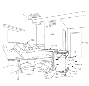
[0008] FIG. 1 is a perspective view of a photo-catalytic oxidation
system treating air
proximate to a foot of a hospital patient's bed in accordance with one method
of the present
disclosure for reducing airborne microbes;
[0009] FIG. 2A is a perspective view of a photo-catalytic oxidation system
according to
one embodiment of the present disclosure; and
[0010] FIG. 2B is a perspective view of a photo-catalytic oxidation
system according to
another embodiment of the present disclosure.
DETAILED DESCRIPTION
[0011] The present disclosure relates to various methods of reducing
airborne
contaminants, such as airborne microbes (e.g., bacteria, viruses, and/or
fungi), in a room or
other indoor space (e.g., a hospital room, a home, a store, an office
building, an airplane
cabin, a cruise line, or a transportation vehicle) with a photo-catalytic
oxidation (PCO)
system. The circulation rate of the air through the PCO system and the
proximity of the PCO
system to a patient infected with a microbial infection or a communicable
disease may be
selected to optimize the efficacy of the PCO system in reducing the overall
microbial load in
the room. Reducing the microbial load in the room mitigates the risk that the
airborne
microbes will spread and infect other individuals. For instance, the methods
of the present
disclosure may be used to reduce the incidence of healthcare associated
infections (HAI),
which are infections acquired by patients during the course of receiving
healthcare treatment
for an unrelated ailment or condition. Additionally, the methods of the
present disclosure may
include positioning the PCO system proximate the source of the airborne
microbes and
operating the PCO system as a multi-pass system in which the air is repeatedly
treated before
the air is recirculated throughout the building.
[0012] With reference now to FIG. 1, a method of reducing airborne
microbes (e.g.,
bacteria, viruses, and/or fungi) in an indoor space or area (e.g., a room)
according to one
embodiment of the present disclosure includes positioning a photo-catalytic
oxidation (PCO)
system 100 proximate a source of airborne microbes (i.e., a source of
contaminants). In the
illustrated embodiment, the PCO system 100 is positioned in a hospital room
101 (e.g., an
emergency department patient room) proximate a patient 102 infected with a
microbial
infection (e.g., a bacterial, viral, and/or fungal infection) or a
communicable disease. In one
or more alternate embodiments, the PCO system 100 may be positioned in any
other suitable
-3-
CA 02959349 2017-02-24
WO 2016/033216 PCT/US2015/046996
1 environment in which it is desired to reduce airborne microbes, such as,
for instance, in
residential rooms, commercial office buildings, or industrial buildings.
Additionally, in the
illustrated embodiment, the PCO system 100 is positioned proximate a foot 103
of the
patient's hospital bed 104. In one or more alternate embodiments, the PCO
system 100 may
be positioned at any other suitable location in the hospital room 101, such
as, for instance,
proximate a head 105 of the patient's hospital bed 104, or along one side 106
of the patient's
hospital bed 104. In one or more alternate embodiments, the PCO system 100 may
be
positioned near any other source of airborne contaminants. Additionally,
although in the
illustrated embodiment only a single PCO system 100 is positioned in the room
101, in one or
more alternate embodiments, a plurality of PCO systems 100 may be positioned
within the
room 101 to accelerate the process of reducing the airborne microbial load in
the room 101.
In one embodiment, the PCO system 100 is positioned a smaller distance from an
exit/entrance doorway 119 of the hospital room 101 than is the patient's 102
mouth when the
patient 102 is in the hospital bed 104, and may be placed substantially
between the
exit/entrance doorway 119 and the patient 102 (e.g., the patient's mouth) when
the patient 102
is in the hospital bed 104. In one embodiment, the PCO system 100 is
positioned between the
patient 102 in the hospital bed 104 and a central heating, ventilation, and
air conditioning
(HVAC) return air duct 120 in the hospital room 101 that is configured to
provide air to the
hospital room 101. Additionally, in one embodiment, the PCO system 100 is
positioned
substantially between the patient 102 in the hospital bed 104 and an HVAC
outlet duct 121
configured to intake air from the hospital room 101 and to distribute and/or
recirculate the air
throughout the hospital.
[0013] With continued reference to the embodiment illustrated in FIG. 1,
the PCO system
100 includes a housing 107 defining a plurality of ducts or vents 108. In the
illustrated
embodiment, the PCO system 100 also includes a base 109 coupled to a lower end
of the
housing 107 and a plurality of wheels 110 coupled to the base 109.
Accordingly, in the
illustrated embodiment, the PCO system 100 is a portable PCO system that
facilitates
repositioning the PCO system 100 within the room 101 (e.g., repositioning the
PCO system
100 around the patient's hospital bed 104) and/or moving the PCO system 100
between
different rooms 101 depending on the nature of the conditions afflicting the
various patients
in the hospital. For instance, the portable PCO system 100 may be wheeled from
one room in
which the patient 102 is not suffering from an infectious disease and into a
patient room 101
in which the patient 102 is suffering from an infectious disease or condition
(e.g., a bacterial,
viral, or fungal infection). In one or more alternate embodiments, the PCO
system 100 may
be a permanent or fixed PCO system located proximate the source of airborne
microbes (e.g.,
the PCO system 100 may be a permanent PCO system located proximate the
hospital bed
104).
-4-
CA 02959349 2017-02-24
WO 2016/033216 PCT/US2015/046996
1 [0014] With reference now to the embodiment illustrated in FIGS. 2A
and 2B, the
housing 107 of the PCO system 100 defines a chamber housing a PCO filter 111.
In the
illustrated embodiment, the PCO filter 111 includes a support medium 112, a
photocatalyst
113 on the support medium 112, and an ultraviolet (UV) light source 114
configured to
irradiate the photocatalyst 113 with UV light beams 115. The irradiation of
the photocatalyst
113 with the UV light beams 115 is believed to produce hydroxyl radicals and
super-oxide
ions and/or other species that are highly reactive with volatile organic
compounds (VOCs)
(e.g., formaldehyde and ammonia), bacterial microbes, viral microbes, and
fungal microbes.
The PCO system 100 also houses a variable speed rate fan configured to draw
contaminated
air 116 in the room 101 through the PCO system 100. In one embodiment, the fan
is
configured to draw approximately 500 ft3/min ("CFM") of contaminated air 116
through the
PCO system 100. In one embodiment, the fan is configured to draw a maximum of
approximately 500 ft3/min ("CFM") of contaminated air 116 through the PCO
system 100,
although in one or more alternate embodiments, the fan may have any other
capacity suitable
for the size of the room 101 in which the PCO system 100 is intended to be
operated, such as,
for instance, greater than approximately 500ft3/min or less than approximately
500ft3/min
(e.g., approximately 100ft3,/min). The housing 107 of the PCO system 100 also
includes
control module or control knob 117 (see FIG. 1) configured to permit an
operator to select the
desired speed of the fan. As the contaminated air 116 is drawn through the PCO
system 100
by the fan, the VOCs and/or microbes in the airstream 116 are oxidized (i.e.,
degraded) as
they are adsorbed on the surface of the photocatalyst 113. In this manner, the
PCO system
100 is configured to produce purified air 118. The fan is also configured to
expel the purified
air 118 out through the ducts or vents 108 in the housing 107 and into the
room 101. In this
manner, the air in the patient room 101 is purified before the air passes to
the remainder of
the hospital by the central heating, ventilation, and air conditioning (HVAC)
outlet vent 121
(see FIG. 1), which reduces the incidence of the airborne microbes spreading
and infecting
other patients in the hospital.
[0015] In one embodiment, the volumetric size of the room 101 and the
airflow capacity
of the PCO system 100 may be selected such that the PCO system 100 is
sufficiently sized
relative to the hospital room 101 to perform_ from approximately 16 to
approximately 32 air
exchanges per hour, such as, for instance, approximately 24 air exchanges per
hour. The
airflow capacity of the PCO system 100 is a function of the fan speed, the
size of the PCO
filter 111, and the air permeability rating ("APR") of the PCO filter 111,
described below. A
single air exchange occurs when the total volume of air in the room 101 has
been treated once
by the PCO system 100. For instance, in an embodiment in which the PCO system
100 is
operating at an airflow capacity of approximately 500 ft3/ min and the room
101 has a
volumetric size of approximately 1250 ft3, the PCO system 100 is configured to
perform
approximately 24 air exchanges per hour. In one embodiment, a ratio of the
airflow capacity
-5-
of the PCO system 100 to the volumetric size of the room 101 may be from
approximately 0.25
to approximately 0.55, such as, for instance, approximately 0.4 (e.g., the PCO
system 100 may
be positioned in a room 101 having a volumetric size such that the PCO system
100 is
configured to perform from approximately 0.25 to approximately 0.55 air
exchanges per minute).
In one embodiment, the method may include operating the PCO system 100 in a
room 101
having a volumetric size from approximately 935 ft3 to approximately 1875 ft3.
In one or more
alternate embodiments, the airflow capacity of the PCO system 100 and the size
of the room 101
in which the PCO system 100 is operating may be selected such that the PCO
system 100 is
configured to perform any other suitable number of air exchanges per hour
depending on a
variety of factors, including the desired rate of oxidation (i.e. degradation)
of the VOCs and
airborne microbes in the air and the initial microbial load in the room 101.
[0016] The support medium H2 may be a silica-based fibrous matte (e.g.,
fiberglass) or
other suitable support material to which the photocatalyst 113 is adhered. The
photocatalyst 113
may be adhered to the support medium 112 in any suitable manner, such as, for
example, as
described in U.S. Patents Nos. 5,766,455 and 5,834,069. The photocatalyst 113
on the support
medium 112 may be a semiconductor catalyst such as a transition metal oxide,
for example
titanium dioxide or other suitable material. Additionally, the photocatalyst
113 may be
metalized or non-metalized. The photocatalyst 113 may be metalized with any
suitable metal
such as, for example, a noble metal, such as platinum and/or palladium. The
addition of platinum
on the photocatalyst 113 is configured to accelerate the oxidation process.
The metal may be
deposited on the photocatalyst 113, if desired, before the photocatalyst 113
is applied to the
support medium 112.
[0017] In one embodiment, the support medium 112 has a minimum
efficiency reporting
value (MERV) rating in a range from approximately 10 to approximately 12,
although in one or
more alternate embodiments, the support medium 112 may have any other suitable
MERV
rating. Additionally, in one embodiment, the support medium 112 is composed of
loosely-packed
fibers such that the support medium 112 has an air permeability rating ("APR")
of greater than
approximately 155 CFM/ft2, such as, for instance, at least approximately 200
CFM/ft2 or at least
approximately 247 CFM/ft2. Loosely packing the fibers of the support medium
112 is configured
to reduce the pressure drop of the air across the support medium 112, which
allows the air to
pass more quickly through the support medium 112. The increased rate of air
circulation through
- 6 -
Date Recue/Date Received 2022-01-05
the PCO system 100 exposes the airborne microbes or other contaminants in the
air to the active
photocatalyst sites on the support medium 112 more frequently, and thus the
airborne microbes
or other contaminants are oxidized (i.e., degraded) more rapidly than with an
otherwise
comparable PCO filter having a lower air permeability rating. In one or more
alternate
.. embodiments, the support medium 112 may be composed of densely-packed
fibers such that the
support medium 112 has an APR of approximately 155 CFM/ft2 or less.
[0018] With continued reference to the embodiments illustrated in FIGS.
2A and 2B, the
support medium 112 of the PCO filter 111 may have any suitable shape, such as,
for instance, a
flat, rectangular shape (i.e., a rectangular prism) (see FIG. 2A) or a pleated
shape (see FIG. 2B).
The pleats increase the surface area of the support medium 112 such that the
pleated support
medium 112 is configured to support more photocatalyst 113 than an otherwise
comparable flat,
rectangular support medium 112 having the same peripheral linear dimensions
(i.e., height and
width) as the pleated support medium 112. Accordingly, the greater number of
active catalytic
sites on the pleated support medium 112 enables a PCO system 100 incorporating
the pleated
support medium 112 to oxidize (i.e., degrade) contaminants in the air more
quickly than a PCO
system 100 incorporating a flat support medium 112 having a smaller surface
area and therefore
fewer active catalytic sites. PCO filters suitable for use with the methods of
the present
disclosure are described in U.S. Patent Application Publication No.
2014/0044591, entitled
"Photocatalytic Oxidation Media and System," and filed August 9, 2013.
[0019] Tests were performed to determine the efficacy of the methods of the
present
disclosure in reducing airborne microbial loads. The PCO systems 100 of the
present disclosure
were placed proximate the foot 103 of hospital beds 104 in a number of patient
rooms within one
emergency depatintent that housed fifty different patients over the course of
the testing period.
Prior to activating the PCO systems 100, the air in each room 101 was tested
to establish the
baseline microbial load in each of the rooms 101. The baseline air sampling
was performed using
three 6-stage Andersen samplers positioned at the head 105 and the foot 103 of
the hospital beds
104 and at an exit/entrance doorway 119 of each hospital room 101. The air
samples were
collected on blood agar plates.
[0020] Following completion of the baseline air sampling, the PCO
systems 100 proximate
the foot 103 of the hospital beds 104 were activated to circulate the
contaminated air 116 in the
room 101 through the PCO system 100. The air 116 was circulated through the
PCO system 100
- 7 -
Date Recue/Date Received 2022-01-05
for approximately 20 minutes before beginning air sampling to determine the
reduction in
microbial load in the rooms 101. In one embodiment, the PCO system 100 had a
maximum
capacity of approximately 500 fe/minute and the rooms 101 had a volumetric
size of
approximately 1250 ft3 such that approximately 8 air exchanges occurred within
the 20-minute
period prior to sampling (i.e., a rate of approximately 24 air exchanges per
hour). A single air
exchange occurs when the total volume of air in the room 101 has been treated
once by the PCO
system 100. After the air 116 was treated by the PCO systems 100 for
approximately 20 minutes,
the air was sampled again with the three 6-stage Anderson samplers in each
room 101. Once the
samples were collected, the blood agar plates were removed from the Anderson
samplers and
placed in an incubator at approximately 37 C. The
-7a-
Date Recue/Date Received 2022-01-05
CA 02959349 2017-02-24
WO 2016/033216 PCT/US2015/046996
1 plates were incubated for approximately 48 hours and then the number of
colonies formed on
the agar plates were calculated and recorded.
[0021] The results of the tests are summarized below in Table 1. For
each location, the
colony count was summed across the 6 stages of the Anderson samplers. The
results are
presented as median values across each of the tested rooms and as
interquartile ranges (i.e.,
the 25th and 75th quartiles) shown in parentheses following the median value.
Table 1 also
indicates the number of patients (N) whose rooms were sampled for each of the
three
locations of the PCO system 100 in the room 101. The p-values were determined
using the
signed Wilcoxon rank-sum test.
Baseline No. Post-Treatment Difference P-Value
Percentage
of Colonies Number of Colonies Difference
Head 14 5.5 -7 <0.001 -54.17% (-
70.00% 48
of Bed (7 to 24) (3 to 12) (-17.75 to 0) to -5.36%)
Foot 11.5 7 -4.5 <0.001 -46.9%(-
66.67% 48
of Bed (6 to 24.25) (4 to 13.75) (-12.5 to -3) to -31.41%)
Exit 9.5 7 -3.5 0.002 -26.67% (-
75.00% 49
of Room (4.25 to 22) (3.25 to 13.75) (-10.75 to -1.75)
to -15.79%)
Total 38.5 20 -15 <0.001 -46.00% (-
66.86% 49
(21 to 68.75) (13.25 to 37.75) (-36.75 to -1) to -15.73%)
Table 1
[0022] Accordingly, operation of the PCO systems 100 at the feet 103 of
the hospital
beds 104 for approximately 20 minutes reduced the microbial load at the heads
105 of the
hospital beds 104 by approximately 54.2%. Operation of the PCO systems 100 at
the feet 103
of the hospital beds 104 for approximately 20 minutes also reduced the
microbial load at the
feet 103 of the beds 104 by approximately 46.9% and at the exit/entrance doors
119 of the
rooms 101 by approximately 26.7%. The lower reduction in the microbial load at
the
exit/entrance door 119 may be due to higher personnel traffic and activity
through and/or
around the exit/entrance door 119 of the room 101 compared to the foot 103 and
the head 105
of the hospital beds 104. That is, unlike a clean room or other sterile
controlled environments,
the patient rooms 101 were open systems in which personnel and other
individuals were
permitted to freely enter and exit the rooms 101 through the doorway 119
during the tests.
[0023] Although in one or more embodiments the PCO systems 100 of the
present
disclosure may be used to reduce airborne contaminants (e.g., airborne
microbes) in a
hospital room, in one or more embodiments, the PCO systems 100 of the present
disclosure
may be used to reduce airborne contaminants, such as airborne microbes (e.g.,
bacteria,
viruses, and/or fungi), in any other type of room or other indoor space or
area, such as, for
instance, in homes, stores, office buildings, airplane cabins, cruise lines,
and transportation
-8-
CA 02959349 2017-02-24
WO 2016/033216 PCT/US2015/046996
1 vehicles (i.e., the PCO systems 100 of the present disclosure may be used
in any indoor space
in which airborne contaminants are desired to be reduced).
[0024] While this invention has been described in detail with particular
references to
exemplary embodiments thereof, the exemplary embodiments described herein are
not
intended to be exhaustive or to limit the scope of the invention to the exact
forms disclosed.
Persons skilled in the art and technology to which this invention pertains
will appreciate that
alterations and changes in the described structures and methods of assembly
and operation
can be practiced without meaningfully departing from the principles, spirit,
and scope of this
invention, as set forth in the following claims. Although relative terms such
as "outer,"
"inner," "upper," "lower," "below," "above," "vertical," "horizontal," and
similar terms have
been used herein to describe a spatial relationship of one element to another,
it is understood
that these terms are intended to encompass different orientations of the
various elements and
components of the invention in addition to the orientation depicted in the
figures.
Additionally, as used herein, the term "substantially" and similar terms are
used as terms of
approximation and not as terms of degree, and are intended to account for the
inherent
deviations in measured or calculated values that would be recognized by those
of ordinary
skill in the art. Moreover, the tasks described above may be performed in the
order described
or in any other suitable sequence. Additionally, the methods described above
are not limited
to the tasks described. Instead, for each embodiment, one or more of the tasks
described
above may be absent and/or additional tasks may be performed. Furthermore, as
used herein,
when a component is referred to as being "on" another component, it can be
directly on the
other component or components may also be present therebetween. Moreover, when
a
component is referred to as being "coupled" to another component, it can be
directly attached
to the other component or intervening components may be present therebetween.
30
-9-