Note: Descriptions are shown in the official language in which they were submitted.
CA 02960195 2017-03-03
WO 2016/040108 PCT/US2015/048340
PRODUCTION OF LOW PRESSURE LIQUID CARBON DIOXIDE
FROM A POWER PRODUCTION SYSTEM AND METHOD
FIELD OF THE DISCLOSURE
The presently disclosed subject matter relates to systems and methods for
production of
liquid carbon dioxide. Particularly, the liquid carbon dioxide can be a low
pressure stream of
carbon dioxide foiined from carbon dioxide produced in a power production
system and method,
specifically a system and method using carbon dioxide as a working fluid.
BACKGROUND
Carbon capture and sequestration (CCS) is a key consideration of any system or
method
that produces carbon dioxide (CO2). This is particularly relevant to power
production through
combustion of a fossil fuel or other hydrocarbon-containing material. Several
power production
methods have been suggested where CCS is achievable. One publication in the
field of high
efficiency power generation with CCS, U.S. Pat. No. 8,596,075 to Allam et at.,
provides for
desirable efficiencies in closed cycle oxy-fuel combustion systems utilizing a
recycle CO2 stream.
In such system, the CO2 is captured as a relatively pure stream at high
pressure.
Current proposals for CO2 disposal often require transportation in high
pressure pipelines as
a high density, supercritical fluid at pressures of 100 bar (10 MPa) to 250
bar (25 MPa). Such
pipelines require high capital expenditures. Piped CO2 is either sequestered
in an underground
geologic formation, such as a deep saline aquifer, or may be used to economic
advantage, such as
for enhanced oil recovery (EOR).
The use of CO2 for FOR necessitates its availability over a wide area of an
oil rich region.
This would require the extensive use of a network of pipelines extending over
the region. This
becomes prohibitively expensive in many uses, particularly off-shore oil
fields. It thus would be
useful to provide bulk quantities of CO2 (such as produced from a power
production system and
method) in liquid foim that would be easier for delivery to off-shore oil
production platforms.
Other beneficial uses of CO2 gathered from power production facilities can be
envisioned if the
CO2 could be provided in a liquefied form.
SUMMARY OF THE DISCLOSURE
The present disclosure provides systems and methods useful in the production
of liquid
CO2. The disclosed systems and methods can make use of CO2 from any source.
The systems and
methods, however, may be particularly beneficial in connection with a system
and method that
-1-
produces a high pressure CO2 stream, particularly a high pressure CO2 stream
at near ambient
temperature. The present systems and methods are further beneficial in that
liquid CO2 can be
produced with substantially high purity, particularly with low levels of
oxygen, nitrogen, and noble
gases (e.g., Argon).
In certain embodiments, a CO2 source that can be used for producing liquid CO2
can be a
power production system, particularly oxyfuel combustion systems and methods,
and more
particularly combustion methods utilizing a CO2 working fluid. Systems and
methods for power
production wherefrom a CO2 stream may be obtained are described in U.S. Pat.
No. 8,596,075,
U.S. Pat. No. 8,776,532, U.S. Pat. No. 8,959,887, U.S. Pat. No. 8,986,002,
U.S. Pat. No. 9,068,743,
U.S. Pub. No. 2010/0300063, U.S. Pub. No. 2012/0067054, U.S. Pub. No.
2012/0237881, and U.S.
Pub. No. 2013/0213049.
In some embodiments, the present disclosure relates to methods for production
of a low
pressure liquid carbon dioxide (CO2) stream. Such methods may
compriseproviding a high
pressure CO2 stream at a pressure of about 60 bar (6 MPa) or greater, about
100 bar (10 MPa) or
greater, or in a pressure range as otherwise disclosed herein. The methods
further may comprise
dividing out a portion of the high pressure CO2 stream and expanding the
portion to form a cooling
stream that may be useful as a refrigerant. For example, the cooling stream
may be at a
temperature of about -20 C or less or in a temperature range as otherwise
disclosed herein. The
methods further may comprise cooling the high pressure CO2 stream to a
temperature of about 5 C
or less (preferably about -10 C or less) by passing the a high pressure CO2
stream through a heat
exchanger in a heat exchange relationship with the cooling stream. The methods
further may
comprise expanding the high pressure CO2 stream so as to form a low pressure
CO2 stream at a
pressure of down to about 6 bar (0.6 MPa). The methods further may comprise
passing the low
pressure CO2 stream through a separator effective to separate a vapor stream
therefrom and provide
the low pressure liquid CO2 stream.
In further embodiments, the present disclosure relates to systems useful in
the production of
a low pressure liquid carbon dioxide (CO2) stream. In some embodiments, such
systems may
comprise one or more components adapted for providing a high pressure CO2
stream, one or more
heat exchangers, one or more expanders (e.g., valves), one or more separators,
and one or more
distillers. In a non-limiting example, a system according to the present
disclosure may comprise:
piping adapted for passage of a high pressure CO2 stream; a divider adapted
for dividing the high
pressure CO2 stream into a cooling fraction and a bulk stream; an expander
adapted for expanding
and cooling the cooling fraction of the high pressure CO2 stream; a heat
exchanger adapted for
-2-
Date Recue/Date Received 2022-01-06
CA 02960195 2017-03-03
WO 2016/040108 PCT/US2015/048340
cooling the bulk high pressure CO2 stream against the wanning expanded and
cooled cooling
fraction of the high pressure CO2 stream; an expander adapted for expanding
and cooling the bulk
high pressure CO2 stream to form a two phase, low pressure CO2 stream; a
separator adapted for
removing a vapor fraction from the two phase, low pressure CO2 stream; and a
distiller adapted for
removing at least a portion of non-0O2 components and providing a low
pressure, liquid CO2
stream.
In still other embodiments, the present disclosure relates to methods for
production of a low
pressure liquid carbon dioxide (CO2) stream from a high pressure CO2 stream
from a power
production process. In some embodiments, such method can comprise combusting a
carbonaceous
or hydrocarbon fuel in a combustor in the presence of oxygen and a recycle CO2
stream at a
pressure of about 100 bar (10 MPa) or greater and a temperature of about 400
C or greater to faun
a combustor exit stream comprising CO2. The combustor exit stream in
particular may be at a
pressure of about 200 bar (20 MPa) to about 400 bar (40 MPa). The combustor
exit stream in
particular may be at a temperature of about 800 C to about 1,600 C. The
method further may
comprise expanding the combustor exit stream in a turbine to generate power
and form a turbine
exit stream comprising CO2 at a pressure of about 50 bar (5 MPa) or less. The
turbine exit stream
particularly may be at a pressure of about 20 bar (2 MPa) to about 40 bar (4
MPa). The method
further may comprise cooling the turbine exit stream in a heat exchanger with
heat transferred to
the heating recycle CO2 stream. Cooling may be to a temperature of about 80 C
or less, such as to
near ambient temperature. The method also may comprise further cooling the
turbine exhaust
stream against ambient cooling means and separating condensed water in a
separator. The method
further may comprise pumping CO2 from the turbine exit pressure to a pressure
of about 100 bar
(10 MPa) or greater to form a high pressure CO2 stream. In particular, the
high pressure CO2
stream may be at a pressure of about 100 bar (10 MPa) to about 500 bar (50
MPa) or about 200 bar
(20 MPa) to about 400 bar (40 MPa). The CO2 from the cooled turbine exit
stream may be
compressed to a first pressure, cooled to increase the density thereof, and
then pumped to the
second, greater pressure in the range noted above. A portion of the high
pressure CO2 stream can
be passed back through the heat exchanger to be heated against the cooling
turbine exit stream prior
to passage back into the combustor. Further heating also may be applied to the
stream after
compression and before passage into the combustor, such further heating coming
from a source
other than the turbine exit stream. A portion of the high pressure CO2 stream
(which portion can
comprise any net CO2 produced in combustion) can be cooled to a temperature of
about 5 C or
less, such as, for example, in a heat exchanger using a refrigerant. The
refrigerant may comprise a
portion of the high pressure CO2 stream that can be utilized as a cooling
fraction by expanding the
-3-
CA 02960195 2017-03-03
WO 2016/040108 PCT/US2015/048340
portion to a pressure that is about 30 bar (3 MPa) or less but is above the
triple point pressure of
CO2. The cooling fraction can be a temperature of about 0 C or less or about -
20 C or less. In
particular embodiments, the cooling fraction of the high pressure CO2 stream
may be cooled to a
temperature of about -55 C to about 0 'C. The portion of the high pressure
CO2 stream that is
cooled in the heat exchanger against the CO2 cooling fraction can be expanded
to a pressure of
down to about 6 bar (0.6 MPa) (preferably always maintaining a pressure above
the triple point
pressure of CO2) so as to form the low pressure liquid CO2 stream. In
particular, the cooled portion
of the high pressure CO2 stream may be expanded to a pressure that is about 30
bar (3 MPa) or less
but is above the triple point pressure of CO2.
Methods as described above further may comprise further elements. For example,
the
cooling of the turbine exit stream particularly may be to a temperature of
about 70 C or less or
about 60 C or less. One heat exchanger or a plurality of heat exchangers may
be used. For
example, an economizer heat exchanger may be used followed by a cold water
heat exchanger.
After cooling, the methods also may comprise passing the turbine exit stream
comprising CO2
through one or more separators to remove at least water therefrom. Further
prior to said pumping
step, the methods may comprise compressing the turbine exit stream comprising
CO2 to a pressure
of up to about 80 bar (8 MPa) (e.g., a pressure of about 60 bar (6 MPa) to
about 80 bar (8 MPa)).
Still further, the methods may comprise increasing the density of the turbine
exit stream comprising
CO2, such as by cooling the stream in a cold water heat exchanger. The
density, for example, may
be increased to about 600 kg/m3 or greater, about 700 kg/m3 or greater, or
about 800 kg/m3 or
greater. The turbine exit stream may be compressed prior to increasing the
density of the stream.
The methods may further comprise, after said cooling of the bulk high pressure
CO2 stream
in a heat exchanger and prior to said expanding, passing the bulk high
pressure CO2 stream through
a re-boiler. The re-boiler may particularly be combined with a distiller
(e.g., a stripping column).
As such, the re-boiler may provide heating to the distiller.
The methods may comprise further processing of the bulk low pressure liquid
CO2 stream.
For example, the low pressure liquid CO2 stream may be a two phase material
including the liquid
phase and a vapor phase. Thus, the methods may comprise passing the low
pressure liquid CO2
stream through a separator effective to separate a vapor stream therefrom. In
some embodiments,
the vapor stream may comprise up to about 8% (particularly up to about 4% or
up to about 6%) by
mass of the low pressure liquid CO2 stream passed through the separator. In
some embodiments,
the vapor stream may comprise about 1% to about 75% by mass CO2. In some
embodiments, the
vapor stream may comprise about 25% to about 99% by mass of a combination of
N2, 02, and
argon (or further inert gases). The methods also may comprise passing the
remaining low pressure
-4-
CA 02960195 2017-03-03
WO 2016/040108 PCT/US2015/048340
liquid CO2 stream (e.g., after withdrawing the vapor phase therefrom) through
a distiller, such as a
stripping column (which may include the re-boiler, as discussed above).
After the distillation step, the liquid CO2 may be provided to a pump to
increase its pressure
to a desired value. The cold discharge stream from the pump may be supplied to
a heat exchanger
upstream of the reboiler to supplement the cooling duty of the high pressure
CO2 that is expanded
to create a refrigerant. The watmed refrigerant CO2 and/or the overhead stream
from a stripping
distillation column may be provided to a compressor that discharges the flow
at a pressure
compatible with the system where the high pressure CO2 stream was sourced. The
vapor phase
stream from the separator may also be provided to a system performing
additional separation
processes. Alternatively, the vapor phase stream may be vented.
The low pressure liquid CO2 stream provided according to the present
disclosure in
particular may have only a very low oxygen concentration. In some embodiments,
the low pressure
liquid CO2 stream may have an oxygen content of no more than about 25 ppm,
particularly no more
than about 10 ppm. The low pressure liquid CO2 stream also may have a
similarly low
concentration of inert gases, such as nitrogen and argon.
As non-limiting examples, the present disclosure can relate to the following
embodiments.
Such embodiments are intended to be illustrative of the broader nature of the
disclosure as a whole.
In some embodiments, the present disclosure can provide methods for production
of a low
pressure liquid CO2 stream. For example, such method can comprise: combusting
a carbonaceous
or hydrocarbon fuel with oxygen in a combustor in the presence of a recycle
CO2 stream at a
pressure of about 100 bar (100 MPa) or greater and a temperature of about 400
C or greater to
form a combustor exit stream comprising CO2; expanding the combustor exit
stream in a turbine to
generate power and farm a turbine exit stream comprising CO2 at a pressure of
about 50 bar (5
MPa) or less; cooling the turbine exit stream in a first heat exchanger to
form a cooled turbine exit
stream; pumping CO2 from the cooled turbine exit stream to a pressure of about
100 bar (10 MPa)
or greater to form a high pressure CO2 stream; dividing the high pressure CO2
stream into a bulk
portion and a cooling portion; expanding the cooling portion of the high
pressure CO2 stream to
reduce the temperature thereof to about -20 C or less; cooling the bulk
portion of the high pressure
CO2 stream to a temperature of about 5 C or less by passing the bulk portion
of the high pressure
CO2 stream through a second heat exchanger against the expanded cooling
portion of the high
pressure CO2 stream; and expanding the cooled, bulk portion of the high
pressure CO2 stream to a
pressure that is about 30 bar (3 MPa) or less but is greater than the triple
point pressure of CO2 so
as to form the low pressure liquid CO2 stream. In further embodiments, such
method may include
one or more of the following statements, which statements may be combined in
any number and
-5-
CA 02960195 2017-03-03
WO 2016/040108 PCT/US2015/048340
any combination. Moreover, such method may include any further elements as
otherwise described
herein.
The combustor exit stream can be at a pressure of about 200 bar (20 MPa) to
about 400 bar
(40 MPa).
The combustor exit stream can be at a temperature of about 800 C to about
1,600 C.
The turbine exit stream comprising CO2 can be at a pressure of about 20 bar (2
MPa) to
about 40 bar (4 MPa).
The turbine exit stream can be cooled in the heat exchanger to a temperature
of about 80 C
or less.
The method further can comprise passing the cooled turbine exit stream
comprising CO2
through one or more separators to remove at least water therefrom.
The method further can comprise heating one or both of the oxygen and the
recycle CO2
stream in the heat exchanger against the turbine exit stream.
The high pressure CO2 stream can be at a pressure of about 200 bar (20 MPa) to
about 400
bar (40 MPa).
The bulk portion of the high pressure CO2 stream can be cooled to a
temperature of about -
55 C to about 0 C.
The method further can comprise, after cooling of the bulk portion of the high
pressure CO2
stream and prior to expanding of the bulk portion of the high pressure CO2
stream, passing the bulk
portion of the high pressure CO2 stream through a re-boiler.
The re-boiler can be in a stripping column.
The method further can comprise passing the low pressure liquid CO2 stream
through a
separator effective to separate a vapor stream therefrom.
The vapor stream can comprise up to about 8% by mass of the low pressure
liquid CO2
stream passed through the separator.
The vapor stream can comprise about 1% to about 75% by mass CO2 and about 25%
to
about 99% by mass of one or more of N2, 02, and Argon.
The method further can comprise passing the remaining low pressure liquid CO2
stream into
a stripping column.
The low pressure liquid CO2 stream exiting the stripping column can have an
oxygen
content of no more than about 25 ppm.
The method can comprise pumping the low pressure liquid CO2 stream to a
pressure of at
least about 100 bar (10 MPa).
The method can comprise delivering the pumped liquid CO2 stream to a CO2
pipeline.
-6-
CA 02960195 2017-03-03
WO 2016/040108 PCT/US2015/048340
The method further can comprise mixing an overhead vapor from the stripping
column with
the cooling portion of the high pressure CO2 stream exiting the second heat
exchanger.
The method further can comprise adding the mixture of the overhead vapor from
the
stripping column and the cooling portion of the high pressure CO2 stream
exiting the second heat
exchanger to the cooled turbine exit stream.
In further exemplary embodiments, the present disclosure can provide systems
configured
for production of a low pressure liquid CO2 stream. For example, a system can
comprise: a splitter
configured for dividing a high pressure CO2 stream into a first portion and a
second portion; a first
expander configured for expanding and cooling the first portion of the high
pressure CO2 stream; a
heat exchanger for cooling the second portion of the high pressure CO2 stream
against the cooled
first portion of the high pressure CO2 stream exiting the expander; and a
second expander
configured for expanding the cooled second portion of the high pressure CO2
stream so as to form
the low pressure liquid CO2 stream. In further embodiments, such system may
include one or more
of the following statements, which statements may be combined in any number
and any
combination. Moreover, such system may include any further elements as
otherwise described
herein.
The first expander can be configured for cooling the first portion of the high
pressure CO2
stream to a temperature of about -20 C or less.
The heat exchanger can be configured for cooling the second portion of the
high pressure
CO2 stream to a temperature of about 5 C or less.
The second expander can be configured to expand the cooled second portion of
the high
pressure CO2 stream to a pressure that is about 30 bar (3 MPa) or less but is
greater than the triple
point pressure of CO2.
The system further can comprise a combined stripping column and re-boiler.
The stripping column can be in line downstream from the second expander, and
the re-
boiler can be in line downstream from the heat exchanger and upstream from the
second expander.
The system further can comprise a liquid/vapor separator positioned downstream
from the
second expander and upstream from the stripping column.
The system further can comprise a compressor configured for receiving the
first portion of
the high pressure CO2 stream from the heat exchanger.
The system further can comprise: a combustor configured for combusting a
carbonaceous or
hydrocarbon fuel with oxygen in a combustor in the presence of a recycle CO2
stream at a pressure
of about 100 bar (10 IVIPa) or greater and a temperature of about 400 C or
greater to faun a
combustor exit stream comprising CO2; a turbine configured for expanding the
combustor exit
-7-
CA 02960195 2017-03-03
WO 2016/040108 PCT/1JS2015/048340
stream to generate power and faun a turbine exit stream comprising CO2; a
further heat exchanger
configured for cooling the turbine exit stream; and a pump configured for
pumping CO2 from the
cooled turbine exit stream to form the high pressure CO2 stream.
The invention includes, without limitation, the following embodiments.
Embodiment 1: A method for production of a low pressure liquid carbon dioxide
(CO2)
stream, the method comprising: combusting a carbonaceous or hydrocarbon fuel
with oxygen in a
combustor in the presence of a recycle CO2 stream at a pressure of about 100
bar (10 MPa) or
greater and a temperature of about 400 C or greater to form a combustor exit
stream comprising
CO2; expanding the combustor exit stream in a turbine to generate power and
form a turbine exit
stream comprising CO2 at a pressure of about 50 bar (5 MPa) or less; cooling
the turbine exit
stream in a first heat exchanger to form a cooled turbine exit stream; pumping
CO2 from the cooled
turbine exit stream to a pressure of about 100 bar (10 MPa) or greater to form
a high pressure CO2
stream; dividing the high pressure CO2 stream into a bulk portion and a
cooling portion; expanding
the cooling portion of the high pressure CO2 stream to reduce the temperature
thereof to about -20
C or less; cooling the bulk portion of the high pressure CO2 stream to a
temperature of about 5 C
or less by passing the bulk portion of the high pressure CO2 stream through a
second heat
exchanger against the expanded cooling portion of the high pressure CO2
stream; and expanding
the cooled, bulk portion of the high pressure CO2 stream to a pressure that is
about 30 bar (3 MPa)
or less but is greater than the triple point pressure of CO2 so as to form the
low pressure liquid CO2
stream.
Embodiment 2: The method of any previous or subsequent embodiment, wherein the
combustor exit stream is at a pressure of about 200 bar (20 MPa) to about 400
bar (40 MPa).
Embodiment 3: The method of any previous or subsequent embodiment, wherein the
combustor exit stream is at a temperature of about 800 'V to about 1,600 C.
Embodiment 4: The method of any previous or subsequent embodiment, wherein the
turbine
exit stream comprising CO2 is at a pressure of about 20 bar (2 MPa) to about
40 bar (4 MPa).
Embodiment 5: The method of any previous or subsequent embodiment, wherein the
turbine
exit stream is cooled in the heat exchanger to a temperature of about 80 C or
less.
Embodiment 6: The method of any previous or subsequent embodiment, further
comprising
passing the cooled turbine exit stream comprising CO2 through one or more
separators to remove at
least water therefrom.
Embodiment 7: The method of any previous or subsequent embodiment, further
comprising
heating one or both of the oxygen and the recycle CO2 stream in the heat
exchanger against the
turbine exit stream.
-8-
CA 02960195 2017-03-03
WO 2016/040108 PCT/US2015/048340
Embodiment 8: The method of any previous or subsequent embodiment, wherein the
high
pressure CO2 stream is at a pressure of about 200 bar (20 MPa) to about 400
bar (40 MPa).
Embodiment 9: The method of any previous or subsequent embodiment, wherein the
bulk
portion of the high pressure CO2 stream is cooled to a temperature of about -
55 C to about 0 C.
Embodiment 10: The method of any previous or subsequent embodiment, further
comprising, after said cooling of the bulk portion of the high pressure CO2
stream and prior to said
expanding of the bulk portion of the high pressure CO2 stream, passing the
bulk portion of the high
pressure CO2 stream through a re-boiler.
Embodiment 11: The method of any previous or subsequent embodiment, wherein
the re-
boiler is in a stripping column.
Embodiment 12: The method of any previous or subsequent embodiment, further
comprising passing the low pressure liquid CO2 stream through a separator
effective to separate a
vapor stream therefrom.
Embodiment 13: The method of any previous or subsequent embodiment, wherein
the vapor
stream comprises up to about 8% by mass of the low pressure liquid CO2 stream
passed through the
separator.
Embodiment 14: The method of any previous or subsequent embodiment, wherein
the vapor
stream comprises about 1% to about 75% by mass CO2 and about 25% to about 99%
by mass of
one or more of N2, 02, and Argon.
Embodiment 15: The method of any previous or subsequent embodiment, further
comprising passing the remaining low pressure liquid CO2 stream into a
stripping column.
Embodiment 16: The method of arty previous or subsequent embodiment, wherein
the low
pressure liquid CO2 stream exiting the stripping column has an oxygen content
of no more than
about 25 ppm.
Embodiment 17: The method of any previous or subsequent embodiment, comprising
pumping the low pressure liquid CO2 stream to a pressure of at least about 100
bar (10 MPa).
Embodiment 18: The method of any previous or subsequent embodiment, comprising
delivering the pumped liquid CO2 stream to a CO2 pipeline.
Embodiment 19: The method of any previous or subsequent embodiment, further
comprising mixing an overhead vapor from the stripping column with the cooling
portion of the
high pressure CO2 stream exiting the second heat exchanger.
Embodiment 20: The method of any previous embodiment, further comprising
adding the
mixture to the cooled turbine exit stream.
-9-
CA 02960195 2017-03-03
WO 2016/040108 PCT/US2015/048340
Embodiment 21: A system configured for production of a low pressure liquid
carbon
dioxide (CO2) stream, the system comprising: a splitter configured for
dividing a high pressure CO2
stream into a first portion and a second portion; a first expander configured
for expanding and
cooling the first portion of the high pressure CO2 stream; a heat exchanger
for cooling the second
portion of the high pressure CO2 stream against the cooled first portion of
the high pressure CO2
stream exiting the expander; and a second expander configured for expanding
the cooled second
portion of the high pressure CO2 stream so as to form the low pressure liquid
CO2 stream.
Embodiment 22: The system of any previous or subsequent embodiment, wherein
the first
expander is configured for cooling the first portion of the high pressure CO2
stream to a
temperature of about -20 'V or less.
Embodiment 23: The system of any previous or subsequent embodiment, wherein
the heat
exchanger is configured for cooling the second portion of the high pressure
CO2 stream to a
temperature of about 5 C or less.
Embodiment 24: The system of any previous or subsequent embodiment, wherein
the
second expander is configured to expand the cooled second portion of the high
pressure CO2 stream
to a pressure that is about 30 bar (3 MPa) or less but is greater than the
triple point pressure of CO2.
Embodiment 25: The system of any previous or subsequent embodiment, further
comprising
a combined stripping column and re-boiler.
Embodiment 26: The system of any previous or subsequent embodiment, wherein
the
stripping column is in line downstream from the second expander and wherein
the re-boiler is in
line downstream from the heat exchanger and upstream from the second expander.
Embodiment 27: The system of any previous or subsequent embodiment, further
comprising
a liquid/vapor separator positioned downstream from the second expander and
upstream from the
stripping column.
Embodiment 28: The system of any previous or subsequent embodiment, further
comprising
a compressor configured for receiving the first portion of the high pressure
CO2 stream from the
heat exchanger.
Embodiment 29: The system of any previous embodiment, further comprising: a
combustor
configured for combusting a carbonaceous or hydrocarbon fuel with oxygen in a
combustor in the
presence of a recycle CO2 stream at a pressure of about 100 bar (10 MPa) or
greater and a
temperature of about 400 C or greater to form a combustor exit stream
comprising CO2; a turbine
configured for expanding the combustor exit stream to generate power and foim
a turbine exit
stream comprising CO2; a further heat exchanger configured for cooling the
turbine exit stream;
-10-
CA 02960195 2017-03-03
WO 2016/040108 PCT/1JS2015/048340
and a pump configured for pumping CO2 from the cooled turbine exit stream to
form the high
pressure CO2 stream.
These and other features, aspects, and advantages of the disclosure will be
apparent from a
reading of the following detailed description together with the accompanying
drawings, which are
briefly described below. The invention includes any combination of two, three,
four, or more of the
above-noted embodiments as well as combinations of any two, three, four, or
more features or
elements set forth in this disclosure, regardless of whether such features or
elements are expressly
combined in a specific embodiment description herein. This disclosure is
intended to be read
holistically such that any separable features or elements of the disclosed
invention, in any of its
various aspects and embodiments, should be viewed as intended to be combinable
unless the
context clearly dictates otherwise.
BRIEF DESCRIPTION OF THE FIGURES
Reference will now be made to the accompanying drawings, which are not
necessarily
drawn to scale, and wherein:
FIG. 1 shows a flow diagram of a system according to embodiments of the
present
disclosure for formation of a low pressure liquid CO2 stream; and
FIG. 2 shows a flow diagram of a system according to embodiments of the
present
disclosure for formation of a low pressure liquid CO2 stream utilizing a
portion of a high pressure
CO2 stream drawn from a power production process.
DETAILED DESCRIPTION
The present subject matter will now be described more fully hereinafter with
reference to
exemplary embodiments thereof These exemplary embodiments are described so
that this
disclosure will be thorough and complete, and will fully convey the scope of
the subject matter to
those skilled in the art. Indeed, the subject matter can be embodied in many
different forms and
should not be construed as limited to the embodiments set forth herein;
rather, these embodiments
are provided so that this disclosure will satisfy applicable legal
requirements. As used in the
specification, and in the appended claims, the singular forms "a", "an",
"the", include plural
referents unless the context clearly dictates otherwise.
The present disclosure relates to systems and methods adapted for production
of low
pressure liquid carbon dioxide (CO2). The systems and methods particularly may
be adapted to
intake a stream comprising non-liquid CO2 (e.g., gaseous CO2 or supercritical
CO2) and convert at
least a portion of the non-liquid CO2 to liquid CO2. The intake stream may
comprise a fraction of
-11-
CA 02960195 2017-03-03
WO 2016/040108 PCT/US2015/048340
liquid CO2; however, the intake stream preferably comprises no more than about
25%, no more
than about 10%, no more than about 5%, or no more than about 2% by weight
liquid CO2.
Liquid CO2 produced according to the present disclosure can be produced at a
low pressure
in that the pressure of the produced liquid CO2 is less than 50 bar (5 MPa)
but greater than the triple
point pressure of CO2 so as to preferably avoid substantial formation of solid
CO2. In some
embodiments, the produced liquid CO2 can be at a pressure of down to about 6
bar (0.6 MPa), in
particular about 30 bar (3 MPa )to about 6 bar 0.6 MPa), about 25 bar 2.5 MPa)
to about 6 bar (0.6
MPa), or about 15 bar (1.5 MPa) to about 6 bar (0.6 MPa). The temperature of
the produced liquid
CO2 preferably is in the range of the saturation temperature at the given
pressure. For example, the
temperature can be in the range of about 5 'V to about -55 C, about -5 C to
about -55 C, or about
-15 C to about -55 C.
Methods of producing liquid CO2 according to embodiments of the present
disclosure
generally can comprise cooling and expanding the CO2 from the intake stream.
Depending upon
the source of the intake stream, the methods may comprise one or more
compression steps. In
preferred embodiments, the intake CO2 can be at a pressure of about 60 bar (6
MPa) or greater,
about 100 bar (10 MPa) or greater, or about 200 bar (20 MPa) or greater. In
other embodiments,
the pressure of the intake CO2 can be in the range of about 60 bar (6 MPa) to
about 400 bar (40
MPa). The temperature of the intake CO2 may be greater than 10 C or may be in
the range of
about 10 C to about 40 C, about 12 C to about 35 C, or about 15 C to
about 30 C. In some
embodiments, the intake CO2 can be at about ambient temperature.
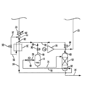
An embodiment of a system and method according to the present disclosure
useful in the
production of liquid CO2 is shown in FIG. 1. As seen therein, a high pressure
CO2 stream 24 may
be cooled by passage through a water cooler 50 (which may be optional
depending upon the actual
temperature of the high pressure CO2 stream). The high pressure CO2 stream 24
is then divided
into a first portion and a second portion using a splitter 68 (or other
suitable system element
configured for dividing a stream) to provide a high pressure CO2 side stream
57 that can be
expanded, such as through a valve 58 or other suitable device, to form a
cooling CO2 stream 56.
The remaining high pressure CO2 stream 62 passes through a heat exchanger 10
where it is cooled
by the cooling CO2 stream 56, which exits as CO2 stream 33. The cooled, high
pressure CO2
stream 51 exiting the cold end of the heat exchanger 10 can be at a
temperature of about 5 C or
less, about 0 C or less, about -10 C or less, or about -20 C or less (for
example, about 5 C to
about -40 C or about 0 C to about -35 C). The cooled, high pressure CO2
stream 51 can be
expanded to foim the liquid CO2 stream. As illustrated in FIG. 1, the cooled,
high pressure CO2
stream 51 first passes through a re-boiler 52, which is part of a stripping
column 53 in FIG. 1, and
-12-
CA 02960195 2017-03-03
WO 2016/040108 PCT/US2015/048340
thus supplies heating for the distillation therein, which is further described
below. Passage through
the re-boiler thus may be optional. The high pressure CO2 stream 55 leaving
the re-boiler 52 is
expanded to foim the low pressure liquid CO2 stream 35 at a temperature and
pressure in the ranges
described above. In FIG. 1, stream 55 is expanded through a valve 48, but any
device useful for
expanding a compressed CO2 stream may be used. For example, the expansion
device can be a
work producing system, such as a turbine, which lowers the enthalpy of the CO2
between the inlet
and the outlet and further lowers outlet temperature.
The expansion of the high pressure CO2 stream (e.g., from the range of about
60 bar (6
MPa) to about 400 bar (40 MPa)) to form the low pressure CO2 stream (e.g., at
a pressure of about
30 bar (3 MPa) or less but greater than the triple point pressure of CO2) can
result in a two phase
product stream formed of a gas and liquid mixture having the same total
enthalpy as the CO2 stream
input to the valve (or other expansion device). The temperature of the two
phase mixture leaving
the valve (or a turbine per the exemplary, alternative embodiment noted above)
particularly can be
at the saturation temperature of the liquid at the reduced pressure. In FIG.
1, stream 56 exiting
valve 58 and stream 35 exiting valve 48 may both be two phase streams. The two
phase, low
pressure CO2 stream 35 exiting valve 48 may be passed through a separator 9 to
provide the CO2
vapor fraction stream 49 and the CO2 liquid fraction stream 36.
In embodiments wherein the input high pressure CO2 stream is from an oxy-
combustion
power production system, the vapor fraction that can be separated from the low
pressure liquid CO2
stream will contain the bulk of the inert gases (e.g., nitrogen, excess 02,
and noble gases, such as
argon) that are present in the oxygen source and the fuel source (e.g.,
natural gas). As a non-
limiting example, an oxy-combustion power production process may be carried
out with a 1%
excess oxygen stream flow into a combustor, the oxygen stream being formed of
approximately
99.5% oxygen and 0.5% argon. The resulting net CO2 product can include 02 at a
2%
concentration and argon at a 1% concentration.
According to the present disclosure, cooling of a CO2 product from a power
system as
exemplified above by indirect cooling means to a temperature which, on
expansion through a valve
to a pressure of, for example, 10 bar (1 MPa), results in a flash vapor
fraction of approximately 4%.
In various embodiments, the vapor fraction may be up to about 6%, up to about
5%, or up to about
4% by mass of the total liquid CO2 stream (e.g., stream 35 in FIG. 1). The
vapor stream (e.g.,
stream 49 in FIG. 1) can comprise about 1% to about 75% by mass CO2 and about
25% to about
99% by mass of a combination of N2, 02, and argon (or other inert gases). In
further embodiments,
the vapor stream can comprise about 60% or greater, about 65% or greater, or
about 70% or greater
by mass of the combination of N2, 02, and argon (or other inert gases). The
flash vapor fraction
-13-
CA 02960195 2017-03-03
WO 2016/040108 PCT/US2015/048340
(e.g., stream 49 leaving the separator 9 in FIG. 1) may be vented to the
atmosphere or captured.
Production of the flash vapor stream is beneficial in embodiments where the
input CO2 stream is
derived from an oxy-combustion process as removal of the vapor fraction will
prevent a build-up of
inert argon and/or nitrogen (which may be present in natural gas and/or coal
derived fuel gas that is
combusted and which may be present in an oxygen stream derived from a
cryogenic air separation
plant). To form the flash vapor fraction, it can be useful to cool the high
pressure CO2 stream (e.g.,
stream 62 in FIG. 1) to a temperature of about -30 C or less or about -33 C
or less prior to
expansion. In embodiments where the input high pressure CO2 stream is from a
source that may be
substantially or completely devoid of inert gases (and optionally oxygen), it
may not be necessary
to form the flash vapor fraction. In embodiments using natural gas fiiel
having a significant
fraction of N2 in the oxy-fuel power production process. it can be useful to
adjust the temperature to
which the stream 51 is cooled so as to ensure the removal of the bulk of the
N2 with the 02 and
argon in stream 49 together with a minimum loss of CO2 in stream 49.
Preferably, the majority of the concentration of 02 and argon (and other inert
gases) from
the input CO2 stream is removed in the flash vapor fraction such that the CO2
liquid fraction stream
(e.g., stream 36 in FIG. 1) has only a minor concentration of N2, 02, and
argon ¨ e.g., about 1% or
less, about 0.5% or less, or about 0.2% or less by mass. This minor
concentration of N2, 02, and
argon can be stripped from the CO2 liquid fraction stream, such as by using a
distillation apparatus
(e.g., the stripping column 53 in FIG. 1). Alternatively to the illustration
of FIG. 1, a stripping
section may be fitted in the lower part of the flash separator. In embodiments
utilizing the stripping
column, a re-boiler (component 52 in FIG. 1 as discussed above) can be
included to withdraw
remaining available heat from part or all of the high pressure CO2 stream
(e.g., stream 51 in FIG.
1). Such heating can be varied to provide the necessary liquid to vapor ratio
to reduce the oxygen
concentration in the net liquid CO2 product (stream 54 in FIG. 1). The oxygen
concentration in the
net liquid CO2 stream can be no more than about 25 ppm, no more than about 20
ppm, or no more
than about 10 ppm.
In further embodiments, the product liquid CO2 stream 54 can be pumped to a
high pressure
and heated in heat exchanger 10 (or in a further heat exchanger or by further
means) for delivery
into a CO2 pipeline. The product liquid CO2 stream particularly may be pumped
to a pressure of
about 100 bar (10 MPa) to about 250 bar (25 MPa).
Returning to FIG. 1, the top product 63 leaving the stripping column 53 may be
further
reduced in pressure if desired, such as in valve 64 and then combined with CO2
stream 33. The
combined streams may be compressed in compressor 34 to provide a return high
pressure CO2
-14-
stream 21, which may be, for example, combined with the input high pressure
CO2 stream 24 or
added to a further CO2 containing stream (see FIG. 2).
The foregoing embodiments for forming a low pressure liquid CO2 stream can be
economically desirable in that about 95% or greater, about 96% or greater, or
about 97% or greater
by mass of the CO2 in the net low pressure CO2 stream (e.g., stream 35 in FIG.
1) can be removed
as the low pressure liquid CO2 stream. In the embodiments described above,
about 1.5% to about
2.5% by mass of the net CO2 product may be vented to the atmosphere with the
combined N2, 02,
and argon stream (e.g., stream 49 in FIG. 1), thus providing a CO2 removal
efficiency of about
97.5% to about 98.5%. In embodiments wherein the above-described method is
carried out in
connection with a closed cycle power system using CO2 as the working fluid,
the stream 49
preferably is vented to the atmosphere because removal of the inert components
is desirable to keep
their partial pressure and concentration as low as possible. Optionally, the
stream 59, following
pressure reduction in valve 60, can be routed through a set of passages in the
heat exchanger 10 to
provide extra refrigeration for cooling the stream 62 before the stream 59 is
vented.
The utilization of an input high pressure CO2 stream 24 provides a unique
ability to provide
indirect cooling to the high pressure CO2 stream. As described in relation to
the embodiments
above, the indirect cooling can be provided by dividing out a portion of the
high pressure CO2
stream at near ambient temperature and then expanding this divided portion of
the high pressure
CO2 stream to a temperature of about -20 C or less, about -30 C or less, or
about -40 C or less
(e.g., approximately -40 C to about -55 C). This can be achieved by reducing
the pressure of the
high pressure CO2 stream 24 down to less than about 20 bar (2 MPa), less than
about 10 bar (1
MPa), or less than about 8 bar (0.8 MPa) (e.g., about 20 bar (2 MPa) to about
5 bar (0.5 MPa) or
about 12 bar (1.2 MPa) to about 5 bar (0.5 MPa), particularly about 5.55 bar
(0.555 MPa)). The
resulting liquid plus vapor stream (e.g., stream 56 in FIG. 1) in then used to
cool the bulk high
pressure CO2 stream indirectly in a heat exchanger.
The systems and methods of the present disclosure are particularly beneficial
when used in
combination with a power production method utilizing a CO2 working fluid, such
as the systems
disclosed in U.S. Pat. No. 8,596,075. In particular, such process can use a
high pressure/low
pressure ratio turbine that expands a mixture of a high pressure recycle CO2
stream and combustion
products arising from combustion of the fuel. Any fossil fuel, particularly
carbonaceous fuels, may
be used. Preferably, the fuel is a gaseous fuel; however, non-gaseous fuels
are not necessarily
excluded. Non-limiting examples include natural gas, compressed gases, fuel
gases (e.g.,
comprising one or ore of H2, CO, CH4, H2S, and NH3) and like combustible
gases. Solid fuels ¨
-15-
Date Recue/Date Received 2022-01-06
e.g., coal, lignite, petroleum coke, bitumen, and the like, may be used as
well with incorporation of
necessary system elements (such as with the use of a partial oxidation
combustor or a gasifier to
convert the solid or heavy liquid fuels to a gaseous form). Liquid hydrocarbon
fuels may also be
used. Pure oxygen can be used as the oxidant in the combustion process. The
hot turbine exhaust
is used to partially preheat the high pressure recycle CO2 stream. The recycle
CO2 stream is also
heated using heat derived from the compression energy of a CO2 compressor, as
further discussed
herein. All fuel and combustion derived impurities such as sulfur compounds,
NO, NO2, CO2,
H20, Hg and the like can be separated for disposal with no emissions to the
atmosphere. A CO2
compression train is included and comprises high efficiency units that ensure
minimum incremental
power consumption. The CO2 compression train can particularly provide a
recycle CO2 fuel
compressor flow that can be recycled in part to the combustor and directed in
part to the liquid CO2
production components as the input high pressure CO2 stream.
Figure 2, for example illustrates a power production system combined with
elements as
described herein to produce the net CO2 product derived from carbon in the
primary fuel in the
form of a low pressure liquid with an oxygen content in a minimal range as
described herein. An
embodiment of such system is described in the Example below in connection to
FIG. 2.
The magnitude of the total CO2 net product flow can be vary depending upon the
nature of
the fuel used. In embodiments utilizing a natural gas fuel, the total CO2 net
product flow can be
about 2.5% to about 4.5% (e.g., about 3.5%) of the total recycle CO2 fuel
compressor flow. In
embodiments utilizing a typical bituminous coal (e.g., Illinois No. 6), the
total CO2 net product
flow can be about 5% to about 7% (e.g., about 6%) of the total recycle CO2
fuel compressor flow.
The quantity of recycled CO2 used for refrigeration can be in the range of
about 15% to about 35%
or about 20% to about 30% (e.g., about 25%) by mass of the net CO2 product
flow.
In some embodiments, liquid natural gas (LNG) can be used as a refrigeration
source in a
manner such as described in U.S. Pat. Pub. No. 2013/0104525. In particular
embodiments, the
LNG can be heated to a temperature approach to the condensing temperature of
the CO2 turbine
exhaust (e.g., at a pressure of about 20 bar (2 MPa) to about 40 bar (4 MPa)).
The turbine exhaust
flow leaving the water separator can be dried in a desiccant drier to a dew
point below about -50 C
before being liquefied using refrigeration derived from the high pressure LNG,
which is in turn
heated. The liquid CO2 can now be pumped to a pressure of about 200 bar (20
MPa) to about 400
bar (40 MPa) using a multi-stage centrifugal pump. The high pressure natural
gas will be at a
temperature typically in the range of about -23 C (for turbine exhaust
leaving the economizer heat
exchanger at about 20 bar (2 MPa)) to about 0 C (for turbine exhaust leaving
the economizer heat
exchanger at
-16-
Date Recue/Date Received 2022-01-06
CA 02960195 2017-03-03
WO 2016/040108 PCT/US2015/048340
about 40 bar (4 MPa)) using a 5 C approach to the saturation temperature of
CO2 at these
pressures. This cold, high pressure natural gas can be used to pre-cool the
high pressure CO2 at
about 60 bar (6 MPa) to about 400 bar (40 MPa) prior to expansion to produce
liquid CO2 in the
pressure range of about 6 bar (0.6 MPa) to about 30 bar (3 MPa). This
refrigeration can be
supplemented by additional refrigeration derived from expansion of high
pressure CO2 as described
above to give a temperature of the cooled net CO2 product which on expansion
to the required
pressure of the liquid CO2 product results in a gas fraction containing about
50% to about 80% by
mass of (02 + N2 Ar). The effect is to significantly reduce the quantity of
additional CO2 which
must be recycled for refrigeration.
EXAMPLE
Embodiments of the present disclosure are further illustrated by the following
example,
which is set forth to illustrate the presently disclosed subject matter and is
not to be construed as
limiting. The following describes an embodiment of a combined power production
system and
method and system and method for production of low pressure liquid CO2, as
illustrated in FIG. 2.
As seen in FIG. 2, a natural gas fuel stream 42 (which in this Example is pure
methane) at
about 40 bar (4 MPa) is compressed to about 320 bar (32 MPa) in a compressor
44 to provide a
compressed natural gas fuel stream 43, which in turn enters a combustion
chamber 1 where it
combusts in a preheated oxidant stream 38, which comprises about 23% by mass
of oxygen mixed
with about 77% by mass of diluent CO2. In the illustrated embodiment, the
total oxygen quantity
contains approximately 1% by mass more oxygen than is required for
stoichiometric combustion.
The combustion products are diluted in the combustor 1 by a heated recycle CO2
stream 37 at about
304 bar (30.4 MPa) and about 707 C. A combustor exit stream 39 at a
temperature of about 1153
C is passed to a turbine 2 inlet, the turbine being coupled to an electric
generator 3 and a main CO2
recycle compressor 4.
The combustor exit stream 39 is expanded in the turbine 2 to provide a turbine
exit stream
45 at about 30 bar (3 MPa) and about 747 C, which in turn is passed through
an economizer heat
exchanger 15 and is cooled to about 56 C leaving as cooled turbine exit
stream 16. The cooled
turbine exit stream 16 is further cooled against cooling water in a water
cooler 7 to near ambient
temperature (stream 17 in FIG. 2). The cooled turbine exit stream 17 is passed
through a separator
6 where a liquid water stream 18 is separated from a gaseous CO2 overhead
stream 19, which itself
is divided into separate flows (streams 22 and 20 in FIG. 2).
The gaseous CO2 overhead bulk stream 22 enters the CO2 recycle compressor 4,
which
operates with an intercooler 5 and compresses the ambient temperature gaseous
CO2 overhead bulk
-17-
CA 02960195 2017-03-03
WO 2016/040108 PCT/US2015/048340
stream 22 (derived from the turbine exit stream 45) from a pressure of about
28.2 bar (2.82 MPa) to
about 63.5 bar (6.35 MPa) ¨ i.e., compressed CO2 stream 23.
The gaseous CO2 overhead fraction stream 20 is used to dilute the 99.5% 02
stream 28
(which is at a pressure of about 28 bar (2.8 MPa)) that is produced by the
cryogenic air separation
plant 14. Combined streams 20 and 28 form the low pressure oxidant stream 26,
which is
compressed to about 320 bar (32 MPa) (stream 27) in a compressor 11 with inter-
coolers 12. The
high pressure oxidant stream 27 is heated in the economizer heat exchanger
leaving as the
preheated oxidant stream 38 at about 304 bar (30.4 MPa) about 707 C.
A first side-stream 32 at about 110 C is taken from the heating high pressure
recycle CO2
flow and heated to about 154 C (stream 31 in FIG. 2) in side heat exchanger
13 against a heat
transfer fluid (entering the side heat exchanger as stream 30 and exiting as
stream 29) which
removes heat of compression from the air compressors in the cryogenic air
separation plant 14.
The ASU has an atmospheric air feed 40 and a waste nitrogen exit stream 41
which is vented to the
atmosphere.
A second side-stream 61 at a temperature of about 400 C is taken from the
heating high
pressure recycle CO2 stream and used in the turbine 2 for internal cooling.
The compressed CO2 stream 23 at about 63.5 bar (6.35 MPa) and about 51 C is
cooled in a
heat exchanger 46 against cooling water to provide stream 47 at about 17.5 C
with a density of
about 820 kg/m3, which is pumped in a multi-stage centrifugal pump 8 to a
pressure of about 305
bar (30.5 MPa). The pump discharge flow is divided into two parts.
High pressure recycle CO2 stream 25 from the pump discharge flow is passed
through the
economizer heat exchanger 15 and functions as the flow from which the first
side-stream and the
second side-stream are taken (as discussed above).
The stream 24 from the pump discharge flow comprises the net CO2 product
stream derived
from carbon in the natural gas. Stream 24 preferably can include an additional
content of CO2 for
use in refrigeration. The additional CO2 content can be up to about 50% by
mass, up to about 40%
by mass, or up to about 30% by mass of the recycle CO2. In some embodiments,
the additional
CO2 content can be about 5% to about 45% by mass, about 10% to about 40% by
mass, or about
15% to about 35% by mass of the recycle CO2.
The high pressure CO2 stream 24 is cooled to near ambient temperature in a
water cooler 50
and divided into two parts. High pressure CO2 fraction stream 57 is reduced in
pressure to about
8.2 bar (0.82 MPa) in valve 58 to form a cooling CO2 stream 56, which is a two
phase mixture at a
temperature of about -45 C. The cooling CO2 stream 56 is passed through heat
exchanger 10
where it evaporates and heats to near ambient temperature leaving as CO2
stream 33.
-18-
CA 02960195 2017-03-03
WO 2016/040108 PCT/US2015/048340
High pressure net CO2 product stream 62 is passed directly into the heat
exchanger 10
where it is cooled against the cooling CO2 stream 56 to a temperature of about
-38 C leaving as
cooled high pressure net CO2 product stream 51. This stream is then passed
through a small re-
boiler 52 in the base of a stripping column 53 leaving as stream 55. This
stream is reduced in
pressure to about 10 bar (1 MPa) in valve 48 to form a two phase net CO2
product stream 35, which
is then passed through a separator 9.
The overhead vapor stream 49 exiting the top of the separator 9 encompasses
about 4% by
mass of the flow of two phase net CO2 product stream 35 and is formed of about
30% by mass CO2
and about 70% by mass of a combination of 02 and argon. The overhead vapor
stream 49 is
reduced in pressure in valve 60 and then vented to the atmosphere (stream 59
in FIG. 2).
Optionally, stream 59 can be heated in heat exchanger 10 to near ambient
temperature providing
extra refrigeration and then further heated to above ambient temperature to
make the vent stream
buoyant.
The liquid CO2 stream 36 exiting the separator 9 at a pressure of about 10 bar
(1 MPa)
comprises about 96% by mass of the flow of two phase net CO2 product stream
35. Stream 36 is
fed to the top of the stripping column 53.
Exiting the bottom of the stripping column 53 is the low pressure liquid CO2
product stream
54, which comprises the net CO2 produced from carbon in the primary fuel feed
to the power
system. In the illustrated embodiment, stream 54 has an oxygen content below
10 ppm.
The top product stream 63 exiting the stripping column 53 is reduced in
pressure to about 8
bar (0.8 MPa) in valve 64 and added to CO2 stream 33. Combined streams 33 and
63 are
compressed in compressor 34 to about 28.5 bar (2.85 MPa). The discharge stream
21 compressed
in the CO2 compressor 34 is mixed with gaseous CO2 overhead bulk stream 22 and
compressed
back up to about 305 bar (30.5 MPa) in the CO2 compressor 4 and the pump 8.
In the above example, specific values (e.g., temperature, pressure, and
relative ratios) are
provided to illustrate working conditions of an exemplary embodiment of the
present disclosure.
Such values are not meant to be limiting of the disclosure, and it is
understood that such values may
be varied within the ranges as otherwise disclosed herein to arrive at further
working embodiments
in light of the overall description provided herein.
Many modifications and other embodiments of the presently disclosed subject
matter will
come to mind to one skilled in the art to which this subject matter pertains
having the benefit of the
teachings presented in the foregoing descriptions and the associated drawings.
Therefore, it is to be
understood that the present disclosure is not to be limited to the specific
embodiments described
herein and that modifications and other embodiments are intended to be
included within the scope
-19-
CA 02960195 2017-03-03
WO 2016/040108 PCT/US2015/048340
of the appended claims. Although specific terms are employed herein, they are
used in a generic
and descriptive sense only and not for purposes of limitation.
-20-