Note: Descriptions are shown in the official language in which they were submitted.
MEDIUM ACCESS CONTROL IN LTE-U
CLAIM OF PRIORITY
[0001] This application claims priority to U.S. Patent Application No.
14/481,808, filed on September 9, 2014.
TECHNICAL FIELD
[0002] This disclosure relates to data transmission in communication systems
and, more specifically, to Medium Access Control (MAC) for LTE in Unlicensed
(LTE-U).
BACKGROUND
[0003] In a wireless communication system, such as a third generation
partnership project (3GPP) long term evolution (LTE) system, the MAC protocol
layer
determines whether a transmission resource is available. This mechanism of the
MAC
protocol determining the transmission opportunity is referred to as
scheduling. For a
Downlink (DL) transmission, a MAC layer scheduler in an evolved Node B (eNB)
may determine when one or more DL packets will be transmitted to a User
Equipment
(UE). The eNB may transmit a DL scheduling grant to the UE on a Physical
Downlink
Control Channel (PDCCH) to indicate the DL channel resource for the
transmission.
For an Uplink (UL) transmission, a UE may request resources for the UL
transmission.
An UL scheduler within the eNB's MAC layer may decide which UE may have access
to the UL channel resources in any given Transmission Time Interval (TTI). The
eNB
may transmit an UL scheduling grant to the HE on a PDCCH to indicate the UL
channel resources for the transmission.
[00041 A wireless communication system, such as an LTE system, may also use
Discontinuous Reception (DRX) procedures to reduce battery power consumption
of a
UE in the system. For example, an eNB may configure a HE to operate in a DRX
configuration mode by transmitting a DRX configuration to the UE. The DRX
configuration may include one or more parameters to indicate when the UE may
activate its receiver and monitor a subframe for the presence of DL or UL
grants on
PDCCH. In some cases, the time when the UE may activate its receiver and
monitor
Date recue / Date received 2021-11-22
CA 02960215 2017-03-03
WO 2016/040254
PCT/US2015/048837
PDCCH is referred to as a DRX active time. In some cases, the DL or UL grants
are
referred to as the DL or UL assignments. During other subframes, the UE may
switch
off its receiver to reduce power consumption. In some cases, these subframes
are
referred to as DRX inactive time. The DRX configuration parameters may include
one
or more timers. The DRX patterns and duty cycles for the DRX active time and
the
DRX inactive time may vary based on the data activity and the one or more
timers.
For example, the DRX configuration parameters may include a DRX inactivity
timer,
which may be set to an initial value and then restarted each time a scheduling
grant for
either UL or DL is received. When the DRX inactivity timer is running, e.g.,
during a
DRX active time, the UE may actively monitor all DL subframes. When the DRX
inactivity timer expires, which may indicate that there has not been any new
UL or DL
assignments for a defined period of time, the UE's monitoring pattern will
change and
the UE may monitor only a reduced number of subframes and turn off part or all
of its
receivers for the remaining downlink subframes to reduce its battery
consumption.
The eNB may use Radio Resource Control (RRC) messages to transmit the DRX
configuration parameters.
DECRIPTION OF DRAWINGS
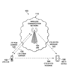
[0005] FIG. 1 is an example wireless communication system 100 that
illustrates an operation in LTE-U.
[0006] FIG. 2 is an example data flow diagram illustrating DRX configuration
switching using MAC signaling.
[0007] FIG. 3 is an example data flow diagram illustrating DRX configuration
switching using RRC signaling.
[0008] FIG. 4 is a flowchart illustrating a method for DRX configuration
__ switching.
[0009] FIG. 5 is an example flowchart illustrating a Listen Before Talk (LBT)
scheme for LTE-U.
[0010] FIG. 6 is a schematic illustrating an example cross-carrier scheduling
method by an eNB.
[0011] FIG. 7 is a schematic illustrating an example cross-scheduling method
for a UE.
2
CA 02960215 2017-03-03
WO 2016/040254
PCT/US2015/048837
[0012] FIG. 8 is a schematic illustrating an example method for handling
collision on a LTE-U Secondary Cell (SCell) carrier.
[0013] FIG. 9 is an example data flow diagram illustrating a channel clearing
method by an eNB for DL transmission.
[0014] FIG. 10 is an example data flow diagram illustrating a timing
relationship for clearing the channel on DL transmission by an eNB.
[0015] FIG. 11 is an example data flow diagram illustrating a channel clearing
method by an eNB for UL transmission.
[0016] FIG. 12 is an example data flow diagram illustrating a timing
relationship for clearing the channel on UL transmission by an eNB.
[0017] FIG. 13 is a flowchart illustrating a channel clearing method by an
eNB.
[0018] FIG. 14 is an example data flow diagram illustrating a channel
assessment method by a UE for UL transmission.
[0019] FIG. 15 is an example data flow diagram illustrating a channel clearing
method by a UE for UL transmission.
[0020] FIG. 16 is an example data flow diagram illustrating a channel clearing
method by both a UE and an eNB for UL transmission.
[0021] FIG. 17 is an example data flow diagram illustrating a channel
assessment method by a UE for UL transmission based on a semi-static grant.
[0022] FIG. 18 is a flowchart illustrating a channel assessment method by a
UE.
[0023] FIG. 19 is a schematic block diagram illustrating an example user
equipment device.
[0024] FIG. 20 is a schematic block diagram illustrating an example base
station.
DETAILED DESCRIPTION
[0025] The present disclosure is directed to Medium Access Control (MAC) in
LIE in Unlicensed (LIE-U). Operators have been looking at a number of ways to
address the spectrum shortage problem. Effectively using unlicensed spectrum
may be
a solution to this problem. For example, a variation of LIE technology may be
used in
unlicensed spectrum to coexist with other wireless devices, such as an 801.11
device.
3
CA 02960215 2017-03-03
WO 2016/040254
PCT/US2015/048837
This technology may be referred to as LTE in Unlicensed (LTE-U) or Licensed-
Assisted Access in LTE (LAA-LTE).
[0026] In LTE-U, eNBs and UEs may use Carrier Aggregation (CA) to transmit
and receive data on a LTE-U carrier. In CA, two or more component carriers
(CCs)
may be simultaneously used to send data to or from the same UE. When a UE is
configured in CA, the UE may have one RRC connection with the eNB. The eNB may
configure a Primary Cell (PCell) carrier and one or more Secondary Cell
(SCell)
carriers for the UE. Tn some cases, an eNB may use cross-carrier scheduling to
transmit scheduling grant to a UE. For example, an eNB may send an UL grant or
a
DL grant on the PDCCH of the PCell carrier to schedule an UL transmission or a
DL
transmission on a SCell carrier. The SCell carrier may be indicated by a
carrier
indicator field (CIF) in the UL grant or DL grant. In LTE-U, an eNB may
configure a
PCell carrier in a licensed spectrum for a UE. For example, the PCell carrier
may be a
LTE carrier that uses LTE spectrum owned by the operator. The eNB may
configure a
SCell carrier in an unlicensed spectrum for the UE. For example, the SCell
carrier
may be a LTE-U carrier that uses unlicensed spectrum.
[0027] FIG. 1 is an example wireless communication system 100 that
illustrates an operation in LTE-U. For example, in a wireless communication
system, a
UE may receive a first Discontinuous Reception (DRX) configuration from an
evolved
NodeB (eNB). While the UE is operating in the first DRX configuration, the UE
may
receive, from the eNB, a DRX Configuration Switch indication that indicates a
switch
to a second DRX configuration. In some implementations, the DRX Configuration
Switch indication may indicate a switch between two existing configurations.
Alternatively or in combination, the DRX Configuration Switch indication may
.. indicate a replacement of an existing configuration with a new
configuration. The
DRX Configuration Switch indication may be received after a load change in an
LTE-
U SCell carrier. In some implementations, the load change in the LTE-U SCell
carrier
may be detected based on a change in at least one of a collision rate on the
LTE-U
SCell carrier, a mean energy level detected on the LTE-U SCell carrier, or a
mean data
rate achieved over the LTE-U SCell carrier. In response to the DRX
Configuration
Switch indication, the UE may switch from the first DRX configuration to the
second
DRX configuration. Other metrics associated with the load of the unlicensed
medium
4
CA 02960215 2017-03-03
WO 2016/040254
PCT/US2015/048837
may also be used. For example, a "medium occupancy factor" may be derived that
is
indicative of a current or averaged fraction of time during which the medium
is
determined to be occupied. In one implementation, the determination as to
whether
the medium is occupied could be based on a comparison of a received signal or
interference level, within at least a portion of an unlicensed band or
carrier, relative to
a threshold. In this case, if the received signal level exceeds the threshold,
the medium
may be classified as "busy", otherwise the medium is classified as "not busy".
The
medium occupancy factor could then be calculated based on the proportion of
busy
time during an observation period. It will be appreciated that other methods
of
determining a medium occupancy factor are also possible, including those that
do not
rely purely on a binary classification of the medium as busy or not-busy. In
such
methods, a distribution or time history of a received signal or interference
level within
the unlicensed band or carrier could be evaluated and a medium occupancy
factor
derived therefrom.
[0028] In some implementations, the DRX Configuration Switch indication
may be received in a Medium Access Control (MAC) Control Element (CE). In some
implementations, the DRX Configuration Switch indication may be included in a
Radio Resource Control (RRC) Connection Reconfiguration message. In some
implementations, the RRC Connection Reconfiguration message may include
parameters associated with the second DRX configuration. In some
implementations,
the -first and the second DRX configurations are preconfigured at the UE. In
some
implementations, the first and second DRX configurations are preconfigured at
the UE
using an RRC Connection Reconfiguration message.
[0029] In some implementations, an eNB may transmit a first DRX
configuration, causing a UE to operate in a first DRX configuration mode. The
eNB
may determine a load change in an LTE-U SCell carrier. Based on the
determining,
the eNB may transmit a DRX Configuration Switch indication that indicates a
switch
to a second DRX configuration, causing the UE to operate in a second DRX
configuration mode.
[0030] In some implementations, an eNB may transmit at least one of a Clear
to Send (CTS) message or a Request to Send (RTS) message on an LTE-U SCell
carrier. The at least one of the CTS message or the RTS message may include a
5
CA 02960215 2017-03-03
WO 2016/040254
PCT/US2015/048837
duration field. The duration field may indicate a transmission time of a
transmission
on a packet data shared channel on the LTE-U SCell carrier. The eNB may
transmit a
scheduling grant for the transmission on the packet data shared channel on the
LTE-U
SCell carrier during the transmission time. In some implementations, the
scheduling
grant may indicate a Physical Downlink Shared Channel (PDSCH) transmission,
and
the eNB may transmit a PDSCH subframe during the transmission time. In some
implementations, the scheduling grant may indicate a Physical Uplink Shared
Channel
(PUSCH) transmission by a UE, and the eNB may receive an Uplink (UL)
transmission request from the UE and a PUSCH subframe during the transmission
time from the UE.
[0031] In some implementations, a UE may receive, from an eNB, an UL grant
that indicates a permission for a PUSCH transmission on an LTE-U SCell carrier
during one or more subframes. In some implementations, the UL grant may be
received on a PDCCH. In some implementations, the UL grant is received on a
Long
Term Evolution (LTE) Primary Cell (PCell) carrier. In some implementations,
the UL
grant is a semi-static UL grant configured using an RRC message. In some
implementations, the UL grant is a dynamic UL grant. In some implementations,
the
UE may transmit at least one of a CTS message or an RTS message on the LTE-U
SCell carrier. The at least one of the CTS message or the RTS message may
include a
duration field. The duration field may indicate a transmission time. The UE
may
determine whether the LTE-U SCell carrier is available for transmission during
the one
or more subframes. In some implementations, the UE determines whether the LTE-
U
SCell carrier is available for transmission based on measuring a signal level
on the
LTE-U SCell carrier. In some implementations, the UE determines whether the
LTE-U
.. SCell carrier is available for transmission based on measuring a signal
level lower than
a threshold. In some implementations, the UE determines whether the LTE-U
SCell
carrier is not available for transmission based on measuring a signal level
higher than a
threshold. If the LTE-U SCell carrier is available for transmission, the UE
may
transmit a PUSCH subframe on the LTE-U SCell carrier. If the LTE-U SCell
carrier is
not available for transmission, the UE may refrain from transmitting on the
LTE-U
SCell carrier. In some implementations, LTE Transmission Time Interval (TTI)
6
CA 02960215 2017-03-03
WO 2016/040254
PCT/US2015/048837
bundling is used when transmitting more than one subframes consecutively in
order to
reduce the time to occupy the SCell carrier.
[0032] Operating the MAC in LTE-U according to methods and systems
described herein may provide one or more advantages. For example, an eNB may
tailor the current DRX configuration of a UE based on the load level of the
LIE-U
carrier. Therefore, the UE may reduce its battery consumption while meeting
the
latency requirement of the data service. In addition, by measuring the signal
level on
the LIE-U carrier before determining whether to transmit, a UE may effectively
use
the unlicensed spectrum when the spectrum is free, while avoiding collisions
and data
loss when the spectrum is busy. Furthermore, sending a CTS or an RTS may
enable
the UE or the eNB to reserve the radio resources in the LIE-U carrier and
therefore
increase the success rate of the data transmission.
[0033] At a high level, the example wireless communication system 100
includes an LIE-U UE 102, an 802.11 device 106, and a wireless communication
network 110, which includes an eNB 104 that is communicably coupled with the
LIE-
U UE 102. In the illustrated example, the eNB 104 configures the LIE-U UE 102
in
CA. The LIE-U UE 102 may transmit to or receive from the eNB 104 on an LIE
PCell carrier 120. The LIE-U UE 102 may also transmit to or receive from the
eNB
104 on an LIE-U SCell carrier 130. In the illustrated example, the LIE-U SCell
carrier 130 operates in unlicensed spectrum.
[0034] In the illustrated example, the LIE-U UE 102 receives a first
Discontinuous Reception (DRX) configuration from the eNB 104. While the LIE-U
UE 102 operates in the first DRX configuration, the LIE-U UE 102 receives a
DRX
Configuration Switch indication from the eNB 104 after a load change in the
LIE-U
SCell carrier 130. The DRX Configuration Switch indication indicates a switch
to a
second DRX configuration. In response to the DRX Configuration Switch
indication,
the LIE-U UE 102 switches from the first DRX configuration to the second DRX
configuration. FIGS. 2-4 and associated descriptions provide additional
details of
these implementations. In some alternatives, the LIE-U UEs may receive
multiple
DRX configurations during the initial connection setup stage, and each DRX
configuration has an index.
7
CA 02960215 2017-03-03
WO 2016/040254
PCT/US2015/048837
[0035] In some instances, the eNB 104 transmits a Clear to Send (CTS)
message or a Request to Send (RTS) message 142 on the LTE-U SCell carrier 130
to
the 802.11 device 106. The CTS message or the RTS message 142 includes a
duration
field. The duration field indicates a transmission time of a transmission on a
packet
data shared channel on the LTE-U SCell carrier 130. The eNB 104 transmits a
scheduling grant for the transmission on the packet data shared channel on the
LTE-U
SCell carrier 130 during the transmission time. FIGS. 5-13 and associated
descriptions
provide additional details of these implementations.
[0036] In some instances, the LIE-U UE 102 receives an UL grant from the
eNB 104. The UL grant indicates a permission for a PUSCH transmission on an
LIE-
U SCell carrier 130 during one or more subframes. In some implementations, the
LIE-U UE 102 transmits a CTS or an RTS message 144 on the LTE-U SCell carrier
130 to the 802.11 device 106. The CTS or the RTS message 144 includes a
duration
field. The duration field indicates a transmission time. The LIE-U UE 102
determines whether the LTE-U SCell carrier 130 is available for transmission
during
the one or more subframes. If the LTE-U SCell carrier 130 is available for
transmission, the LIE-U UE 102 transmits a PUSCH subframe on the LIE-U SCell
carrier 130. If the LIE-U SCell carrier 130 is not available for transmission,
the LIE-
U UE 102 refrains from transmitting on the LIE-U SCell carrier 130. FIGS. 14-
18
and associated descriptions provide additional details of these
implementations.
[0037] Turning to a general description of the elements, a UE may be referred
to as mobile electronic device, user device, mobile station, subscriber
station, portable
electronic device, mobile communications device, wireless modem, or wireless
terminal. Examples of a UE (e.g., the LIE-U UE 102) may include a cellular
phone,
personal data assistant (PDA), smart phone, laptop, tablet personal computer
(PC),
pager, portable computer, portable gaming device, wearable electronic device,
or other
mobile communications device having components for communicating voice or data
via a wireless communication network. The wireless communication network may
include wireless link over a licensed spectrum or over an unlicensed spectrum.
[0038] Other examples of a UE include, but are not limited to, a television, a
remote controller, a set-top box, a computer monitor, a computer (including a
tablet, a
desktop computer, a handheld or laptop computer, a netbook computer), a
microwave,
8
CA 02960215 2017-03-03
WO 2016/040254
PCT/US2015/048837
a refrigerator, a stereo system, a cassette recorder or player, a DVD player
or recorder,
a CD player or recorder, a VCR, an MP3 player, a radio, a camcorder, a camera,
a
digital camera, a portable memory chip, a washer, a dryer, a washer/dryer, a
copier, a
facsimile machine, a scanner, a multi-functional peripheral device, a
wristwatch, a
clock, and a game device, etc. A UE may include a device and a removable
memory
module, such as a Universal Integrated Circuit Card (UICC) that includes a
Subscriber
Identity Module (SIM) application, a Universal Subscriber Identity Module
(USIM)
application, or a Removable User Identity Module (R-UIM) application. The term
"UE" can also refer to any hardware or software component that can terminate a
communication session for a user. In addition, the terms "user equipment,"
"UE,"
"user equipment device," "user agent," "UA," "user device," and "mobile
device" can
be used synonymously herein.
[0039] The wireless communication network 110 may include one or a
plurality of radio access networks (RANs), core networks (CNs), and external
networks. The RANs may comprise one or more radio access technologies. In some
implementations, the radio access technologies may be Global System for Mobile
communication (GSM), Interim Standard 95 (IS-95), Universal Mobile
Telecommunications System (UMTS), CDMA2000 (Code Division Multiple Access),
Evolved Universal Mobile Telecommunications System (UMTS), Long Term
Evaluation (LTE), or LTE_Advanced. In some instances, the core networks may be
evolved packet cores (EPCs).
[0040] A RAN is part of a wireless telecommunication system which
implements a radio access technology, such as UMTS, CDMA2000, 3GPP LTE, and
3GPP LTE-A. In many applications, a RAN includes at least one eNB 104. An eNB
104 may be a radio base station that may control all or at least some radio
related
functions in a fixed part of the system. The eNB 104 may provide radio
interface
within their coverage area or a cell for the LTE-U UE 102 to communicate. The
eNB
104 may be distributed throughout the cellular network to provide a wide area
of
coverage. The eNB 104 directly communicates to one or a plurality of UEs,
other base
stations, and one or more core network nodes.
[0041] An 802.11 device may be any device that operates in unlicensed
spectrum. Examples of an 802.11 device (e.g., the 802.11 device 106) may
include a
9
CA 02960215 2017-03-03
WO 2016/040254
PCT/US2015/048837
cellular phone, personal data assistant (PDA), smart phone, laptop, tablet
personal
computer (PC), pager, portable computer, portable gaming device, wearable
electronic
device, access point, access terminal, or other mobile communications device
having
components for communicating voice or data over unlicensed spectrum. Examples
of
unlicensed spectrum may include spectrum that uses IEEE 802.11 wireless local
area
network technology.
[0042] While described in terms of FIG. 1, the present disclosure is not
limited
to such an environment. In general, wireless communication systems may be
described as cellular networks made up of a number of radio cells, or cells
that are
each served by a base station or other fixed transceiver. The cells are used
to cover
different areas in order to provide radio coverage over an area. Example
wireless
communication systems include Global System for Mobile Communication (GSM)
protocols, Universal Mobile Telecommunications System (UMTS), 3GPP Long Term
Evolution (LTE), and others. In addition to wireless communication systems,
wireless
broadband communication systems may also be suitable for the various
implementations described in the present disclosure. Example wireless
broadband
communication system includes IEEE 802.11 wireless local area network, IEEE
802.16 WiMAX network, and etc.
[0043] FIG. 2 is an example data flow diagram 200 illustrating DRX
configuration switching using MAC signaling. In the illustrated example, the
eNB 104
communicates with the LTE-U UE 102 to adaptively switch DRX configurations. In
the illustrated example, the eNB 104 schedules transmissions on the LTE-U
SCell
carrier using PDCCH on the downlink in the LTE-U SCell carrier. The LTE-U UE
102
monitors the PDCCH on the LTE-U SCell carrier for scheduling grants. In the
illustrated example, the LTE-U UE 102 is configured to operate in DRX mode.
The
LTE-U UE 102 therefore monitors the PDCCH on the LTE-U SCell carrier during
DRX active time. In some implementations, the eNB 104 determines whether the
LTE-U SCell carrier is busy. In such a case, the eNB 104 may transmit DL
packet or
scheduling grant when the LTE-U SCell carrier is not busy.
[0044] At step 210, the eNB 104 transmits an RRC message to the LTE-U UE
102. In the illustrated example, the RRC message is an
RRCConnectionReconfiguration message. The RRC message includes a DRX
CA 02960215 2017-03-03
WO 2016/040254
PCT/US2015/048837
configuration for high load and a DRX configuration for low load. In some
alternatives, the RRC messages may include more than two DRX configurations. A
DRX configuration for high load includes parameters that may keep a UE awake
(i.e.
listening to the PDCCH in downlink) more often. For example, a DRX
configuration
for high load may include shorter DRX cycles, longer inactivity timers, longer
ON
duration timers, and etc. A DRX configuration for low load includes parameters
that
may keep a UE asleep more often, and thereby reduce the UE's power
consumption.
For example, a DRX configuration for low load may include longer DRX cycles,
shorter inactivity timers, longer ON duration timers, and etc.
[0045] At step 220, the LTE-U UE 102 sends an
RRCConnectionReconfigurationComplete to the eNB 104 to indicate that the
RRCConnectionReconfiguration message has been successfully received. In the
illustrated example, the LTE-U UE 102 enters into DRX mode using the DRX
configuration for high load.
[0046] At step 230, the eNB 104 detects low load on the unlicensed spectrum,
i.e., the LTE-U SCell carrier. The eNB 104 may determine the load on the LTE-U
SCell carrier based on one or more factors. These factors may include
collision rates
on the LTE-U SCell carrier, mean energy levels detected on the LTE-U SCell
carrier,
mean data rates achieved over the LTE-U SCell carrier, and medium occupancy
factors. When the load on the LTE-U SCell carrier is low, the probability of
getting
access through the LTE-U SCell carrier is high. Thus, the latency requirement
of the
data traffic can be satisfied by using the DRX configuration for low load. The
eNB
104 therefore sends a DRX Configuration Switch indication to the LTE-U UE 102.
In
some implementations, the DRX Configuration Switch indication may be
transmitted
in a MAC Control Element (CE). The LTE-U UE 102 receives the DRX
Configuration Switch indication and switches from the DRX configuration for
high
load to the DRX configuration for low load.
[0047] At step 240, the eNB 104 detects high load on the LTE-U SCell carrier.
In such a case, the probability of getting access through the LTE-U SCell
carrier is low.
Thus, the latency of the downlink traffic may be high in this scenario because
of the
unavailability of the LTE-U SCell carrier. The eNB 104 therefore sends a DRX
Configuration Switch indication to the LTE-U UE 102. The LTE-U UE 102 receives
11
CA 02960215 2017-03-03
WO 2016/040254
PCT/US2015/048837
the DRX Configuration Switch indication and switches from the DRX
configuration
for low load to the DRX configuration for high load.
[0048] In some implementations, the eNB 104 may configure more than two
DRX configurations for the LTE-U UE 102. The eNB 104 therefore may use DRX
Configuration Switch indication to instruct the LTE-U UE 102 to switch to any
of the
preconfigured DRX configurations. Following is an example portion of 3GPP TS
36.321 specification that may support switching DRX configurations using MAC
CE.
In this example, 8 different DRX configurations can be preconfigured and the
MAC
CE based signaling is used to switch between these configurations.
Index LCID values
00000 CCCH
00001-01010 Identity of the logical channel
01011-11000 Reserved
11001 DRX Config Switch
11010 Long DRX Command
11011 Activation/Deactivation
11100 UE Contention Resolution Identity
11101 Timing Advance Command
11110 DRX Command
11111 Padding
Table 6.2.1-1 Values of LCID for DL-SCH
6.1.3.10 DRX Config Switch MAC Control Element
The DRX Config Switch MAC control element (CE) is identified by a MAC PDU
subheader
with LCID as specified in table 6.2.1-1. It has a fixed size and consists of a
single octet defined as
follows:
- R: reserved bit, set to "0";
- DRX Config Switch: this field indicates the index of DRX
preconfigurations. The length of the
field is 3 bits, identifying 8 different DRX preconfigurations in the UE.
Value 0 identifies DRX
preconfiguartion 0, value 1 identifies DRX preconfiguration 1, and so on.
12
CA 02960215 2017-03-03
WO 2016/040254
PCT/US2015/048837
1 1 1 1 1 1 1 1 1
R R R RR DRX Config Oct 1
Switch
Table 6.2.1-2 DRX Config Switch MAC control element
[0049] FIG. 3 is an example data flow diagram 300 illustrating DRX
configuration switching using RRC signaling. In the illustrated example, the
eNB 104
communicates with the LIE-U UE 102 to adaptively switch DRX configurations. In
the illustrated example, the eNB 104 schedules transmissions on the LIE-U
SCell
carrier using PDCCH on the downlink in LIE-U SCell carrier. As discussed
above,
the LIE-U UE 102 is configured to operate in DRX mode and therefore monitors
the
PDCCH on the LIE-U SCell carrier during DRX active time.
[0050] At step 310, the eNB 104 determines that the load on the LIE-U SCell
carrier is low. The eNB 104 transmits an RRC message to the LTE-U UE 102. In
the
illustrated example, the RRC message is an RRCConnectionReconfiguration
message.
The RRC message includes a DRX configuration for low load. In some
implementations, the eNB 104 may preconfigure more than one DRX configurations
for the LTE-U UE 102.
[0051] At step 320, the LIE-U UE 102 sends an
RRCConnectionReconfigurationComplete to the eNB 104 to indicate that the
RRCConnectionReconfiguration message has been successfully received. The LIE-U
UE 102 enters into DRX mode using the DRX configuration for low load.
[0052] At step 330, the eNB 104 detects high load on the LIE-U SCell carrier.
The eNB 104 therefore sends a DRX Configuration Switch indication to the LIE-U
UE 102. In some implementations, the DRX Configuration Switch indication may
be
transmitted in an RRC message. In the illustrated example, the RRC message is
an
RRCConnectionReconfiguration message. In some implementations, the RRC
.. message may include parameters associated with the DRX configuration for
high load.
The LIE-U UE 102 receives the DRX Configuration Switch indication and switches
from the DRX configuration for low load to the DRX configuration for high
load. At
step 332, the LIE-U UE 102 sends an RRCConnectionReconfigurationComplete to
the
eNB 104.
[0053] At step 340, the eNB 104 detects low load on the LIE-U SCell carrier.
The eNB 104 therefore sends a DRX Configuration Switch indication to the LIE-U
13
CA 02960215 2017-03-03
WO 2016/040254
PCT/US2015/048837
UE 102. In some implementations, the DRX Configuration Switch may be
transmitted
in an RRC message. In the illustrated example, the RRC message is an
RRCConnectionReconfiguration message. The LTE-U UE 102 receives the DRX
Configuration Switch indication and switches from the DRX configuration for
high
load to the DRX configuration for low load. At step 342, the LTE-U UE 102
sends an
RRCConnectionReconfigurationComplete to the eNB 104. In some alternative, when
multiple DRX configurations are configured, the DRX Configuration Switch
indication may include the index of the intended DRX configuration.
[0054] FIG. 4 is a flowchart 400 illustrating a method for DRX configuration
switching. The flowchart begins at step 402 where a UE receives a first
Discontinuous
Reception (DRX) configuration from an evolved NodeB (eNB). In some
implementations, at step 404, the eNB preconfigures the second DRX
configurations
for the UE.
[0055] At step 406, while the UE is operating in the first DRX configuration,
the UE receives, from the eNB, a DRX Configuration Switch indication that
indicates
a switch to a second DRX configuration. The DRX configuration switch
indication is
received when certain conditions occur, for example, after a load change in an
LTE-U
SCell carrier. In some implementations, the load change in the LTE-U SCell
carrier
may be detected by the eNB based on a change in at least one of a collision
rate on the
LTE-U SCell carrier, a mean energy level detected on the LTE-U SCell carrier,
a mean
data rate achieved over the LTE-U SCell carrier, or a medium occupancy factor.
In
some implementations, the DRX Configuration Switch indication may be received
in a
Medium Access Control (MAC) Control Element (CE). In some implementations, the
DRX Configuration Switch indication may be included in a Radio Resource
Control
(RRC) Connection Reconfiguration message. In some implementations, the RRC
Connection Reconfiguration message may also include parameters associated with
the
second DRX configuration. At step 408, in response to the DRX Configuration
Switch
indication, the UE switches from the first DRX configuration to the second DRX
configuration.
[0056] FIG. 5 is an example flowchart 500 illustrating a Listen Before Talk
(LBT) scheme for LTE-U. The LBT scheme may be implemented by an LBT module
in different devices, e.g., the eNB 104 or the LTE-U UE 102. The flowchart 500
14
CA 02960215 2017-03-03
WO 2016/040254
PCT/US2015/048837
begins at step 510 where a Clear Channel Assessment (CCA) is made to determine
whether the medium is busy. For example, the eNB 104 may determine whether the
LTE-U SCell carrier is busy before transmitting in downlink. The LIE-U UE 102
may
also determine whether the LIE-U SCell carrier is busy before transmitting in
the
uplink. In some implementations, the LBT module may listen to the LIE-U SCell
carrier for its availability. In order to determine if the medium is busy or
not, the LBT
module may detect transmissions on the LIE-U SCell carrier using a number of
methods. For example, the LBT module may detect RF energy on the carrier,
802.11
preamble transmission on the carrier, LIE-U signal transmitted on the carrier,
or
RADAR/Primary user signal transmitted on the carrier.
[0057] If the medium is busy, at step 512, the LBT module prevents the device
from transmitting on the LIE-U SCell carrier. In some implementations, if a
transmission on the LIE-U SCell carrier is detected, the LBT module may wait
for an
Inter Frame Spacing (IFS) period. In some implementations, multiple IFSs may
be
defined. For example, a Short IFS (SIFS) may be used by higher priority
transmissions such as Request to Send (RTS) or Clear to Send
(CTS)/Acknowledgement (ACK) transmissions. These transmissions can occur after
the SIFS has elapsed. For other transmissions, the carrier may be accessed on
a
contention basis after a Distributed Coordination Function (DCF) IFS (DIFS)
has
expired. An SIFS may be on the order of lOus and a DIFS may be on the order of
50us. The values of IFSs may vary depending on the technologies used in the
unlicensed spectrum. In addition, a Point Coordination Function Interftame
Space
(PIFS) may be defined. The value of PIFS is between DIFS and SIFS and
therefore
provides a slightly higher priority for channel access compared to a device
using DIFS.
.. In some implementations, after an IFS period, e.g., a DIFS period, the LBT
module
may wait for an additional Backoff period before transmitting on the carrier.
A
randomly drawn time delay parameter may be defined for the Backoff period. The
Backoff period may be decremented after every interval that the channel is
quiet for a
period DIFS. In some implementations, a contention window (C Window) timer is
used to prevent a device that has just completed an atomic frame transfer
operation
from accessing the carrier again too quickly, e.g., before other devices have
had a
chance to access the carrier.
CA 02960215 2017-03-03
WO 2016/040254
PCT/US2015/048837
[0058] If the medium is not busy, then at step 514, the LBT module instructs
the device to transmit on the LTE-U SCell carrier. The following table
illustrates an
example of the interaction between the LBT scheme and the MAC scheduling
decisions.
Table 1: Interaction between LTE-U LBT scheme and the MAC scheduling decisions
LTE-U LBT scheme output
Medium busy Medium not busy
cc
=, , Grant No transmission transmission
allowed
cu
ii
w
u "0
No Grant No transmission No transmission
[0059] FIG. 6 is a schematic 600 illustrating an example cross-carrier
scheduling method by an eNB. The schematic 600 includes an LTE PCell carrier
610
and an LTE-U SCell carrier 640. The LTE PCell carrier 610 includes a PDCCH 612
and a PDSCH 614. The LTE-U SCell carrier 640 includes a PDSCH 642. A UE1 630,
a UE2 632, and a UE-3 634 are LTE-U UEs that operate in both the LTE PCell
carrier
610 and the LTE-U SCell carrier 640. In the illustrated example, cross-
scheduling is
used and therefore the UE1 630, the UE2 632, and the UE3 634 monitor the PDCCH
612 on the LTE PCell carrier 610 for scheduling grants of the LTE-U SCell
carrier 640.
If a UE operates in DRX mode, then the eNB may transmit scheduling grants when
the
UE is in a DRX inactive time on the LTE PCell carrier.
[0060] FIG. 7 is a schematic 700 illustrating an example cross-scheduling
method for a UE. The schematic 700 includes an LTE PCell carrier 710 and an
LTE-
U SCell carrier 720. The LTE PCell carrier 710 includes a PDCCH 712 and a
PDSCH
714. In the illustrated example, a UE monitors the PDCCH 712 on the LTE PCell
carrier 710 for scheduling grants of the LTE-U SCell carrier 720.
[0061] FIG. 8 is a schematic 800 illustrating an example method for handling
collision on the LTE-U SCell carrier. The schematic 800 includes an LTE PCell
carrier
810 and an LTE-U SCell carrier 820. The LTE PCell carrier 810 includes a PDCCH
812 and a PDSCH 814 at subframe #0. The LTE PCell carrier 810 also includes a
PDCCH 822 and a PDSCH 824 at subframe #n. The LTE-U SCell carrier 820 includes
a PDSCH 830 at subframe tin. Because the LTE PCell carrier 810 operates in
licensed
spectrum, the eNB may not use the LBT scheme to transmit scheduling grants or
DL
16
CA 02960215 2017-03-03
WO 2016/040254
PCT/US2015/048837
data on the LTE PCell carrier 810. On the other hand, the eNB may use the LBT
scheme to transmit on the LTE-U SCell carrier 820.
[0062] In the illustrated example, the eNB makes a scheduling decision to
transmit on both the LTE PCell carrier 810 and the LTE-U SCell carrier 820 at
subframc #0. The eNB then determines that the LIE-U SCell carrier 820 is not
available based on the LBT scheme. In such a case, the eNB may transmit on the
LTE
PCell carrier 810, which includes both scheduling grants on the PDCCH 812 and
DL
data on the PDSCH 814. The UE may therefore receive a cross-carrier downlink
scheduling grant for the LTE-U SCell carrier 820 but no DL transmission on the
LTE-
U SCell carrier 820 at subframe #0. The UE may determine that there is no DL
transmission on the LIE-U SCell carrier 820 at subframe #0 by determining that
transmission addressed to the UE's CRNTI was not received on the LIE-U SCell
carrier 820. In the illustrated example, the UE may continue to monitor the
LIE-U
SCell carrier 820 for downlink subframes until a subframe addressed to the UE
is
received on the LIE-U SCell carrier 820. The UE may also send an HARQ
feedback,
e.g., an HARQ NACK, to the eNB on the LTE PCell UL to indicate that the UE has
received the scheduling grant in the subframe #0. The UE may continue to
monitor
DL transmissions after the DRX inactivity timer has expired. For example, the
UE
may start or restart the DRX related timers such as inactivity timer upon
receiving a
cross-carrier scheduled grant for the LIE-U SCell carrier 820 and continue
listening to
the LTE-U SCell carrier 820 if at least one of the following conditions holds
true: 1)
the DRX timers indicate that the UE is in a DRX active time, or 2) a downlink
frame
addressed to the UE has not yet been received after the latest PDCCH grant on
the LTE
PCell carrier 810. At subframe #n, when the eNB detects that the LIE-U SCell
carrier
820 is free, the eNB may send another scheduling grant on the PDCCH 822 to
indicate
a corresponding DL data transmission on the PDSCH 830 of the LIE-U SCell
carrier
820. Following is an example portion of 3GPP IS 36.321 specification that may
support the collision handling method described above.
When a DRX cycle is configured, the Active Time includes the time while:
onDurationTimer or drx-InactivityTimer or drx-RetransmissionTimer or mac-
ContentionResolutionTimer (as described in subclausc 5.1.5) is running; or
a Scheduling Request is sent on PUCCH and is pending (as described in
subclause
5.4.4); or
17
CA 02960215 2017-03-03
WO 2016/040254
PCT/US2015/048837
an uplink grant for a pending HARQ retransmission can occur and there is data
in the
corresponding HARQ buffer; or
a PDCCH indicating a new transmission addressed to the C-RNTI of the UE has
not
been received after successful reception of a Random Access Response for the
preamble not selected by
the UE (as described in subclause 5.1.4); or
a PDCCH indicating a new transmission addressed to the C-RNTI of the UE has
been
received indicating a cross-carrier scheduled downlink subframe on an
unlicensed carrier and the
corresponding transmission on PDSCH of the unlicensed carrier has not yet been
received
[0063] FIG. 9 is an example data flow diagram 900 illustrating a channel
clearing method by an eNB for downlink transmission. In the illustrated
example, the
eNB 104 communicates with the LTE-U UE 102 on both the LTE PCell carrier and
the
LIE-U SCell carrier. At step 910, the MAC scheduler in the eNB 104 schedules a
transmission on the LIE-U SCell carrier. At step 920, the eNB 104 performs CCA
and sends either an RTS message or a CTS message on the LTE-U SCell carrier
prior
to transmission of a subframe on the LTE-U SCell carrier. The RTS message or
the
CTS message may include a duration field. The duration field may indicate a
time
period for which the LIE-U SCell carrier is going to be occupied for data
transmission. Other devices that operate in the LIE-U SCell carrier may
receive the
RTS or the CTS and update the Network Allocation Vector (NAV). The NAV field
then implicitly indicates to the other devices that the LIE-U SCell carrier is
likely to
be busy during the period of time as indicated by the duration field.
[0064] At step 930, the CTS or RTS messages are transmitted to clear the
channel on the LIE-U SCell carrier. In some implementations, a transmitter,
e.g., the
eNB 104, may include a destination address (RA) in the RTS message and sends
the
RTS. On receiving the RTS, the receiver (identified by the RA in the RTS
message)
may transmit a CTS message and sends the CTS back to the transmitter. Since
both the
RTS and CTS messages have the same impact of muting the listening devices for
the
time period as indicated by the duration field, devices near the transmitter
and receiver
may refrain from transmitting during the period. In some implementations, the
eNB
times the transmission of the RTS or CTS message such that the subsequent
scheduled
transmission on LIE-U SCell carrier is kept clear of interference.
[0065] At step 940, during the transmission time indicated by the duration
field
of the CTS or RTS message, the eNB 104 transmits a scheduling grant of the LIE-
U
18
CA 02960215 2017-03-03
WO 2016/040254
PCT/US2015/048837
SCell carrier on the PDCCH of the LIE PCell carrier to the LIE-U UE 102. The
eNB
104 also transmits DL data on the LIE SCell carrier to the LIE-U UE 102.
[0066] FIG. 10 is an example data flow diagram 1000 illustrating a timing
relationship for clearing the channel on downlink transmission by an eNB. In
the
illustrated example, the eNB 104 communicates with the LIE-U UE 102 on both
the
LIE PCell carrier and the LIE-U SCell carrier. The eNB 104 also sends RTS/CTS
to
the 802.11 device 106 on the LIE-U SCell carrier. At step 1010, the eNB 104
determines to grant DL resources on the LIE-U SCell carrier. At step 1020, the
eNB
104 broadcasts an RTS/CTS message to clear the LIE-U SCell carrier at the
scheduled
transmission time. As shown in the illustrated example, the window of
opportunity for
transmission of the RTS or CTS message starts after the eNB 104 makes the
scheduling decision on the LIE-U SCell carrier. In some implementations, the
eNB
104 may send the RTS or CTS message close in time to the actual PDSCH
transmission. This approach may keep the LTE-U SCell carrier busy while
setting a
smaller value in the duration field. In some implementations, the RTS or CTS
message may be addressed to a pseudo MAC address or to a MAC address
associated
with the eNB 104 itself. Upon receiving the RTS/CTS message, the 802.11 device
106
may update the NAV to note that the LIE-U SCell carrier is reserved. Other
devices
operating in the LIE-U SCell carrier, e.g., any other LIE-U eNBs or Wi-Fi
devices,
may also read the RTS or CTS message and update the NAY. In order to perform
the
initial transmission and subsequent retransmissions within the short duration,
multiple
redundancy versions of a transport block may be consecutively transmitted in
consecutive TTIs, similar to III bundling in uplink direction. Downlink TTI
bundling
may be indicated by PDCCH.
[0067] At step 1030, the eNB 104 may transmit on the LIE-U SCell carrier to
the LIE-U UE 102 as scheduled. Following is an example portion of 3GPP TS
36.212
specification that may support the channel clearing method described above.
19
CA 02960215 2017-03-03
WO 2016/040254
PCT/US2015/048837
4.2 Downlink
Table 4.2-1 specifies the mapping of the downlink transport channels to their
corresponding
physical channels. Table 4.2-2 specifies the mapping of the downlink control
channel information to its
corresponding physical channel.
Table 4.2-1
TrCH (Transport Channel) Physical Channel
DL-SCH (Downlink shared PDSCH
channel)
BCH (Broadcast Channel) PBCH (Physical Broadcast
Channel)
Pal (Paging Channel) PDSCH
MCH (Multicast Channel) PMCH (Physical Multicast
Channel)
Table 4.2-2
Control information Physical Channel
CFI (control format indicator) PCFICII (Physical Control Format
Indicator Channel)
III (HARQ indicator) PHICH (Physical HARQ indicator
Channel)
DCI (Downlink control indicator) PDCCH, EPDCCH (Enhanced
PDCCH)
. .
Channel coding, multiplexing and interleaving
5.3.3.1.2 Format 1
DCI format 1 is used for the scheduling of one PDSCII codeword in one cell.
The following information is transmitted by means of the DCI format 1:
- Carrier indicator ¨ 0 or 3 bits. This field is present according to the
definitions in [3].
- When the carrier indicator corresponds to a carrier in unlicensed spectrum,
the cNB
shall monitor the availability of the carrier and transmit a CTS message [See
IEEE Std
802.11Tm-2012, Part 11] prior to transmission of the PDSCH on the carrier to
ensure that
this carrier is available for the transmission of the PDSCH codcword. The
timing of the
transmission is left to eNB implementation but should be transmitted close in
time to the
transmission instance of the PDSCH but prior to the PDSCH transmission and the
indicated duration in the CTS message shall cover the period of the PDSCH
transmission.
[0068] FIG. 11 is an example data flow diagram 1100 illustrating a channel
clearing method by an eNB for UL transmission. In the illustrated example, the
eNB
CA 02960215 2017-03-03
WO 2016/040254
PCT/US2015/048837
104 communicates with the LTE-U UE 102 on both the LIE PCell carrier and the
LTE-U SCell carrier. The eNB 104 also sends RTS/CTS to the 802.11 device 106
on
the LTE-U SCell carrier. At step 1110, the LIE-U UE 102 sends a Scheduling
Request
(SR) to the eNB 104 to request UL transmission. In some implementations, the
SR
may be transmitted on the LIE PCell carrier. Alternatively or in combination,
the SR
may be transmitted on the LIE-U SCell carrier. At step 1120, the eNB 104
determines
to grant a set of UL resources on the LIE-U SCell carrier. At step 1130, the
eNB 104
transmits an UL grant for PUSCH transmission of the LIE-U SCell carrier. Tbe
eNB
104 may transmit the UL grant on the LIE PCell carrier. In the illustrated
example,
the eNB 104 transmits the UL grant at subframe #SN to grant an UL transmission
at
subframe #SN+4. At step 1140, the eNB 104 broadcasts a CTS or an RTS message
to
the 802.11 device 106. As described previously, the CTS or RTS message may
include
a duration field indicating the specific number of subframes for the scheduled
UL
transmission. In some implementations, III bundling is not used and the
specific
number of subframes may be 1. Alternatively or in combination, III bundling is
used
and the specific number of subframes may be 4. Upon receiving the RTS/CTS
message, the 802.11 device 106 may update the NAV to note that the LIE-U SCell
carrier is reserved. Other devices operating in the LIE-U SCell carrier, e.g.,
any other
LIE-U eNBs or Wi-Fi devices, may also read the RTS or the CTS and update the
NAV.
Clearing channels by eNB for UL transmission may have one or more advantages.
For
example, this approach pushes the implementation of the LBT scheme in the eNB
and
reduces the implementation complexities at the UE. At step 1150, the eNB 104
receives the PUSCH transmission on the LIE-U SCell carrier from the LTE-U UE
102.
[0069] FIG. 12 is an example data flow diagram 1200 illustrating a timing
relationship for clearing the channel on UL transmission by an eNB. In the
illustrated
example, the eNB 104 communicates with the LIE-U UE 102 on both the LIE PCell
carrier and the LIE-U SCell carrier. The eNB 104 also sends RTS/CTS to the
802.11
device 106 on the LIE-U SCell carrier. At step 1210, the LIE-U UE 102 sends a
Scheduling Request (SR) to the eNB 104 to request UL transmission. At step
1220,
the eNB 104 determines to grant UL resource on the LIE-U SCell carrier. At
step
1230, the eNB 104 transmits an UL grant for PUSCH transmission on the LIE-U
21
CA 02960215 2017-03-03
WO 2016/040254
PCT/US2015/048837
SCell carrier. In the illustrated example, the eNB 104 transmits the UL grant
at
subframe #SN to grant an UL transmission at subframe #SN+4. In some
implementations, the eNB 104 may schedule UL transmissions for more than one
LIE-
U UEs on the same UL subframe using frequency domain scheduling (resources as
indicated on the PDCCH for each UE).
[0070] At step 1240, the eNB 104 broadcasts a CTS or an RTS message to the
802.11 device 106. As described previously, the eNB may send the RTS or CTS
message close in time to the actual PUSCH transmission on the LTE-U SCell
carrier.
In some implementations, the RTS or CTS message may be addressed to a pseudo
MAC address or to a MAC address associated with the eNB 104 itself. Other
devices
operating in the LIE-U SCell carrier, e.g., any other LIE-U eNBs or Wi-Fi
devices,
may also read the RTS or CTS and update the NAV. At step 1250, the eNB 104
receives the PUSCH transmission on the LIE-U SCell carrier from the LTE-U UE
102. Following is an example portion of 3GPP IS 36.212 specification that may
support the channel clearing method described above.
5.3.3.1.1Format 0
DCI format 0 is used for the scheduling of PUSCII in one UL cell.
The following information is transmitted by means of the DCI format 0:
= - Carrier indicator ¨ 0 or 3 bits.
- When the carrier indicator corresponds to a carrier in unlicensed spectrum,
the eNB shall
monitor the availability of the carrier and transmit a CTS message prior to
the occurrence of
the scheduled PUSCH subframe on the carrier to ensure that this carrier is
available for the
transmission of the PUSCH codeword. The timing of the transmission of CTS is
left to eNB
implementation but the indicated duration in the CTS frame should occur close
in time to the
scheduled PUSCH frame and shall cover the period of the PUSCH transmission.
[0071] FIG. 13 is a flowchart 1300 illustrating a channel clearing method by
an
eNB. The flowchart 1300 begins at step 1310, where an eNB receives an Uplink
(UL)
transmission request from a UE. In some instances, e.g., when a DL
transmission is
scheduled, step 1310 may be omitted. At step 1320, the eNB transmits at least
one of a
.. Clear to Send (CTS) message or a Request to Send (RTS) message on an LTE-U
SCell
carrier. The at least one of the CTS message or the RTS message includes a
duration
field. The duration field indicating a transmission time of a transmission on
a packet
data shared channel on the LTE-U SCell carrier. In some implementations, the
transmission time indicated by the duration field is set from the time that
the CTS
22
CA 02960215 2017-03-03
WO 2016/040254
PCT/US2015/048837
message or the RTS message is received. For example, in such a case, the
duration
field may be set to 8 subframes, which indicates that the transmission time
include the
8 subframes after the subframe that the CTS or RTS message is received.
Alternatively or in combination, the duration field may be set from a
predefined time
relative to the time that the CTS message or the RTS message is received. In
some
implementations, the predefined time may be set by an eNB. For example, the
eNB
may set the predefined time to be 4 subframe. In such a case, if the duration
field is set
to 8 subframes, the transmission time may include the time from the .5th
subframe after
the subframe that the CTS or RTS message is received to the 12th subframe. The
eNB
may transmit a scheduling grant for the transmission on the packet data shared
channel
on the LTE-U SCell carrier during the transmission time. In some instances, at
step
1330, the eNB transmits a DL scheduling grant, which indicates a Physical
Downlink
Shared Channel (PDSCH) transmission. The eNB also transmits a PDSCH subframe
during the transmission time. In some instances, at step 1332, the eNB
transmits an
UL scheduling grant, which indicates a Physical Uplink Shared Channel (PUSCH)
transmission by a UE. In such a case, at step 1334 the eNB receives a PUSCH
subframe during the transmission time from the UE.
[0072] FIG. 14 is an example data flow diagram 1400 illustrating a channel
assessment method by a UE for UL transmission. In the illustrated example, the
eNB
104 communicates with the LTE-U UE 102 on both the LTE PCell carrier and the
LTE-U SCell carrier. At step 1410, the LTE-U UE 102 sends a Scheduling Request
(SR) to the eNB 104 to request UL transmission. At step 1420, the eNB 104
determines to grant UL resource on the LTE-U SCell carrier. At step 1430, the
eNB
104 transmits an UL grant for PUSCH transmission of the LTE-U SCell carrier.
The
eNB 104 may transmit the UL grant on the LTE PCell carrier. In the illustrated
example, the eNB 104 transmits the UL grant at subframe #SF to grant an UL
transmission at subframe #SF+4. In some implementations, the LTE-U UE 102 may
perform CCA before accessing the LTE-U SCell on the granted subframe. The CCA
may be based on the LBT scheme. In some implementations, the LBT module in the
LTE-U UE 102 may measure the signal level on the LTE-U SCell carrier. If the
measured signal level is higher than a threshold, then the LTE module
determines that
the LTE-U SCell carrier is busy. If the measured signal level is lower than a
threshold,
23
CA 02960215 2017-03-03
WO 2016/040254
PCT/US2015/048837
then the LTE module determines that the LTE-U SCell carrier is free. In some
implementations, if the measured signal level is equal to a threshold, the LTE
module
may determine that the LIE-U SCell carrier is busy. Alternatively, if the
measured
signal level is equal to a threshold, the LTE module may determine that the
LIE-U
SCell carrier is free.
[0073] If the LBT scheme indicates that the LIE-U SCell carrier is busy, then
the LIE-U UE 102 may refrain from transmitting on the LIE-U SCell carrier. In
some implementations, the eNB 104 may treat the ignored grant as a missed
uplink
frame. In such a case, the eNB 104 may send a new grant to provide a
retransmission
opportunity for the missed PUSCH subframe. Alternatively or in combination,
the
eNB 104 may send a HARQ NACK on the LTE PCell carrier, which may trigger a
non-adaptive retransmission, which may be transmitted without a scheduling
grant. If
the LBT scheme indicates that the LIE-U SCell carrier is free, then at step
1440, the
LIE-U UE 102 may transmit on the PUSCH of the LIE-U SCell carrier during the
subframe #SF+4. In some implementations, the LIE-U UE 102 may use LTE III
bundling to transmit on the PUSCH for more than one subframes.
[0074] FIG. 15 is an example data flow diagram 1500 illustrating a channel
clearing method by a UE for UL transmission. In the illustrated example, the
eNB 104
communicates with an LIE-U UE1 1502 and an LIE-U UE2 1508 on both the LTE
PCell carrier and the LIE-U SCell carrier. The LIE-U UE1 1502 and the LIE-U
UE2
1508 also send RTS/CTS to the 802.11 device 106 on the LIE-U SCell carrier. At
step
1510, the LTE-U UE1 1502 sends a Scheduling Request (SR) to the eNB 104 to
request UL transmission. At step 1520, the eNB 104 determines to grant a set
of UL
resources on the LIE-U SCell carrier to the LIE-U UE1 1502 and a different set
of UL
resources on the LIE-U SCell carrier to the LIE-U UE2 1508. At step 1530, the
eNB
104 transmits an UL grant-1 to the LIE-U UE1 1502 and an UL grant-2 to the LIE-
U
UE2 1504. The eNB 104 may transmit both UL grants on the LTE PCell carrier. In
the illustrated example, the eNB 104 transmits both UL grants at subframe #SF
to
grant UL resources at subframe #SF+4.
[0075] At step 1540, both the LIE-U UE1 1502 and the LIE-U UE2 1508
transmit an RTS message or a CTS message to other devices operating in the LIE-
U
SCell carrier, including the 802.11 device 106. Because the RTS or CTS message
is
24
CA 02960215 2017-03-03
WO 2016/040254
PCT/US2015/048837
used to clear other devices (e.g Wi-Fi devices and/or other eNBs) from the
scheduled
subframe, broadcasting the RTS or CTS message by more than one UEs may
increase
the chances that other devices may receive the message and refrain from
transmitting.
In some implementations, the LTE-U UE1 1502 and/or the LTE-U UE2 1508 may
.. transmit the RTS or CTS message close in time to the actual UL
transmission. In
some implementations, the RTS or CTS message may be addressed to a pseudo MAC
address or to a MAC address associated with the UE that transmits the RTS or
CTS
message. At step 1560, both the LTE-U UE1 1502 and the LTE-U UE2 1508 transmit
UL at subframc #SF+4 using the UL resources assigned in their respective UL
grants.
[0076] FIG. 16 is an example data flow diagram 1600 illustrating a channel
clearing method by both a UE and an eNB for UL transmission. In the
illustrated
example, the eNB 104 communicates with the LTE-U UE1 1502 and the LTE-U UE2
1508 on both the LIE PCell carrier and the LTE-U SCell carrier. The LIE-U UE1
1502, the LTE-U UE2 1508, and the eNB 104 also send RTS/CTS to the 802.11
device
106 on the LIE-U SCell carrier. At step 1610, the LTE-U UE1 1502 sends a
Scheduling Request (SR) to the eNB 104 to request UL transmission. At step
1620,
the eNB 104 determines to grant a set of UL resources on the LIE-U SCell
carrier to
the LTE-U UE1 1502 and a different set of UL resources on the LIE-U SCell
carrier to
the LIE-U UE2 1508. At step 1630, the eNB 104 transmits an UL grant-1 to the
LIE-
.. U UE1 1502 and an UL grant-2 to the LIE-U UE2 1504. The eNB 104 may
transmit
both UL grants on the LIE PCell carrier. In the illustrated example, the eNB
104
transmits both UL grants at subframe #SF to grant UL resources at subframe
#SF+4.
[0077] At step 1640, the eNB 104 transmits an RTS or CTS message to other
devices operating in the LIE-U SCell carrier, including the 802.11 device 106.
At step
1642, both the LIE-U UE1 1502 and the LIE-U UE2 1508 transmit an RTS or CTS
message to other devices operating in the LIE-U SCell carrier, including the
802.11
device 106. Transmitting CTS or RTS message by both the eNB and the UEs
enhances the coverage of the channel clearing method. For example, this
approach
may help to clear channel for devices near either the eNB or the UEs. At step
1660,
both the LIE-U UE1 1502 and the LIE-U UE2 1508 transmit UL data at subframe
#SF+4 using the UL resources assigned in their respective UL grants. Following
is an
CA 02960215 2017-03-03
WO 2016/040254
PCT/US2015/048837
example portion of 3GPP TS 36.213 specification that may support the channel
clearing method described above.
8.0 UE procedure for transmitting the physical uplink shared
channel
The term "UL/DL configuration" in this subclause refers to the higher layer
parameter
subframeAssignment unless specified otherwise.
For FDD and normal HARQ operation, the UE shall upon detection on a given
serving cell of a
PDCCH/EPDCCH with DCI format 0/4 and/or a PHICH transmission in subframe n
intended for the
UE, adjust the corresponding PUSCH transmission in subframe n+4 according to
the PDCCH/EPDCCH
and PHICH information. If the PDCCH/EPDCCH refers to a cross-carrier scheduled
subframe on an
unlicensed carrier, the UE shall monitor the availability of the carrier and
transmit a CTS message prior
to the occurrence of the scheduled PUSCH subframe on the carrier to ensure
that this carrier is available
for the transmission of the PUSCH codeword. The timing of the transmission of
the CTS is left to UE
implementation but it should be transmitted close in time to the PUSCH
transmission and the indicated
duration in the CTS frame should cover the period of the scheduled PUSCH
transmission as indicated in
by the PDCC1-11EPDCCH DCI format 0/4.
[0078] FIG. 17 is an example data flow diagram 1700 illustrating a channel
assessment method by a UE for UL transmission based on a semi-static grant. In
the
illustrated example, the eNB 104 communicates with the LTE-U UE 102 on both
the
LTE PCell carrier and the LTE-U SCell carrier. At step 1710, the eNB 104
transmits a
semi-static UL grant. The semi-static UL grant may grant a permission to
transmit on
the UL of the LTE-U SCell carrier during one or more predetermined subframes.
The
eNB 104 may also preconfigure the semi-static frequency domain resources
(resource
blocks) for different UEs at the predetermined subframes to minimize the
collisions.
At step 1720, the UE may determine to transmit an UL packet at a first
predetermined
subframe. Before transmitting, the LTE-U UE 102 may perform CCA based on the
LBT scheme to determine whether the LTE-U SCell carrier is busy. At step 1730,
if
the LTE-U SCell carrier is free, the LTE-U UE 102 transmits on the PUSCH of
the
LTE-U SCell carrier. In some implementations, the LTE-U UE 102 may include a
UE
identifier (e.g. it's CRNT1) in the transmitted subframc. For example, the
PUSCH data
frame may include a CRNTI MAC CE. If the LTE-U SCell carrier is busy, the LTE-
U
UE 102 may refrain from transmitting at the first predetermined subframe.
Alternatively or in combination, the LTE-U UE 102 may transmit a CTS or an RTS
message to clear the channel before the transmitting on the first
predetermined
subframe.
26
CA 02960215 2017-03-03
WO 2016/040254 PCT/US2015/048837
[0079] At step 1740, the LIE-U UE 102 may determine to transmit another UL
packet at a second predetermined subframe. Before transmitting, the LIE-U UE
102
may perform CCA based on the LBT scheme to determine whether the LIE-U SCell
carrier is busy. At step 1750, if the LIE-U SCell carrier is free, the LIE-U
UE 102
transmits on the PUSCH of the LIE-U SCell carrier. If the LIE-U SCell carrier
is
busy, the LIE-U UE 102 may refrain from transmitting at the second
predetermined
subframe. Alternatively or in combination, the LIE-U UE 102 may transmit a CTS
or
an RTS message to clear the channel before the transmitting on the second
predetermined subframe. Scheduling transmission on the LTE-U SCell carrier
using
semi-static grant described above may have one or more advantages. For
example,
this approach may reduce overhead of resource requests and grants. This
approach
may also reduce latency and increase performance for delay sensitive services,
which
may be indicated by the QCI of the associated data traffic.
[0080] In some implementations, an RRC Information Element (IE) may be
used to configure semi-static transmissions as described above. The RRC IE may
be
included in an RRCConneetionReconfiguration message transmitted from the eNB
104
to the LTE-U UE 102. Following is a definition of an IE, lteuSCellUlConfig,
which
may provide an example of the structure and contents of the IE.
25 -µ . ,
_ = , \
27
CA 02960215 2017-03-03
WO 2016/040254 PCT/US2015/048837
CSR-PUSCH-Config field descriptions
lteu-RIV
Resource Indication Value for transmissions on LIE-U SCell in UL. Specifies
both the number of
consecutive virtual resource blocks reserved for PUSCH transmissions and the
starting virtual
resource block for the resource (see section 8.1 of IS 36.213). The number of
RIVs is a function of
the number of UL resource blocks NRBul- within the system bandwidth and is
ecival to NRiv =
ceil((NRB-1)*( NRB +1)/2). Choice parameters b5, b6, b13 correspond to
log2(NRiv).
Iteu-MCS
MCS indication field defininq both the transport block size and the modulation
order to be used on the
Iteu resource. Corresponds to parameter Imcs of section 8.6.1 of 36.213. The
eNB may send a new
IteuSCellUIConfig to change the MCS to be used by the UE.
Iteu-DMRSshift
Cyclic shift for demodulation reference signals. Corresponds to the cyclic
shift field in table 5.5.2.1.1-1
of IS 36.211.
[0081] FIG. 18 is a flowchart 1800 illustrating a channel assessment method by
a UE. The flowchart 1800 begins at step 1810, where a UE receives, from an
eNB, an
UL grant that indicates a permission for a PUSCH transmission on an LTE-U
SCell
carrier during one or more subframes. In some implementations, the UL grant
may be
received on a Physical Downlink Control Channel (PDCCH). In some
implementations, the UL grant is received on a Long Term Evolution (LTE)
Primary
Cell (PCell) carrier. In some implementations, the UL grant is a semi-static
UL grant
configured using an RRC message. In some implementations, at step 1820, the UE
transmits at least one of a CTS message or an RTS message on the LTE-U SCell
carrier, wherein the at least one of the CTS message or the RTS message
includes a
duration field, the duration field indicating a transmission time.
[0082] At step 1830, the UE measures a signal level on the LTE-U SCell
carrier. At step 1840, the UE determines whether the LTE-U SCell carrier is
available
for transmission during the one or more subframes. In some implementations,
the UE
determines whether the LTE-U SCell carrier is available for transmission based
on the
measured signal level. If the measured signal level is higher than a
threshold, at step
1850, the UE determines that the LTE-U SCell carrier is not available for
transmission
and refrains from transmitting on the LTE-U SCell carrier. If the measured
signal level
is lower than a threshold, at step 1852, the UE determines that the LTE-U
SCell carrier
is available for transmission and transmits a PUSCH subframe on the LTE-U
SCell
carrier. In some implementations, if the measured signal level is equal to a
threshold,
the LTE module may determine that the LTE-U SCell carrier is busy.
Alternatively, if
the measured signal level is equal to a threshold, the LTE module may
determine that
the LTE-U SCell carrier is free. In some implementations, the UE uses LTE
28
CA 02960215 2017-03-03
WO 2016/040254
PCT/US2015/048837
Transmission Time Interval (TTI) bundling when transmitting more than one
subframes consecutively according to the configuration by the eNB.
[0083] FIG. 19 is a schematic block diagram 1900 illustrating an example user
equipment device. The illustrated device 1900 includes a processing unit 1902,
a
computer readable storage medium 1904 (for example, ROM or flash memory), a
wireless communication subsystem 1906, a user interface 1908, and an I/0
interface
1910.
[0084] The processing unit 1902 can include one or more processing
components (alternatively referred to as "processors" or "central processing
units"
.. (CPUs)) configured to execute instructions related to one or more of the
processes,
steps, or actions described above in connection with one or more of the
implementations disclosed herein. In some implementations, the processing
module
1902 may be configured to generate control information, such as a measurement
report,
or respond to received information, such as control information from a network
node.
.. The processing module 1902 may also be configured to make a RRM decision
such as
cell selection/reselection information or triggering a measurement report. The
processing unit 1902 can also include other auxiliary components, such as
random
access memory (RAM) and read only memory (ROM). The computer readable storage
medium 1904 can store an operating system (OS) of the device 1900 and various
other
computer executable software programs for performing one or more of the
processes,
steps, or actions described above.
[0085] The wireless communication subsystem 1906 may be configured to
provide wireless communication for data and/or control information provided by
the
processing unit 1902. The wireless communication subsystem 1906 can include,
for
.. example, one or more antennas, a receiver, a transmitter, a local
oscillator, a mixer,
and a digital signal processing (DSP) unit. In some implementations, the
subsystem
1906 can support multiple input multiple output (MIMO) transmissions. In some
implementations, the receivers in the wireless communication subsystems 1906
can be
an advance receiver or a baseline receiver. Two receivers can be implemented
with
identical, similar, or different receiver processing algorithms.
[0086] The user interface 1908 can include, for example, one or more of a
screen or touch screen (for example, a liquid crystal display (LCD), a light
emitting
29
CA 02960215 2017-03-03
WO 2016/040254
PCT/US2015/048837
display (LED), an organic light emitting display (OLED), a micro-
electromechanical
system (MEMS) display), a keyboard or keypad, a trackball, a speaker, and a
microphone. The I/0 interface 1910 can include, for example, a universal
serial bus
(USB) interface. Various other components can also be included in the device
1900.
[0087] FIG. 20 is a schematic block diagram 2000 illustrating an example base
station. The illustrated device 2000 includes a processing module 2002, a
wired
communication subsystem 2004, and a wireless communication subsystem 2006. The
wireless communication subsystem 2006 can receive data traffic and control
traffic
from the UE. In some implementations, the wireless communication subsystem
2006
may include a receiver and a transmitter. The wired communication subsystem
2004
can be configured to transmit and receive control information between other
access
node devices via backhaul connections. The processing module 2002 can include
one
or more processing components (alternatively referred to as "processors" or
"central
processing units" (CPUs)) capable of executing instructions related to one or
more of
the processes, steps, or actions described above in connection with one or
more of the
implementations disclosed herein. The processing module 2002 can also include
other
auxiliary components, such as random access memory (RAM), read only memory
(ROM), secondary storage (for example, a hard disk drive or flash memory). The
processing module 2002 can form at least part of the layers described above in
connection with FIG. 2. In some implementations, the processing module 2002
may
be configured to generate control information or respond to received
information such
as a measurement report transmitted from a UE. The processing module 2002 may
also
be configured to make a RRM decision based at least in part on the information
transmitted from the UE, such as cell selection/reselection information or the
measurement report. The processing module 2002 can execute certain
instructions and
commands to provide wireless or wired communication, using the wired
communication subsystem 2004 or a wireless communication subsystem 2006.
Various other components can also be included in the device 2000.
[0088] A number of embodiments of the invention have been described.
Nevertheless, it will be understood that various modifications may be made
without
departing from the spirit and scope of the invention. Accordingly, other
embodiments
are within the scope of the following claims.
CA 02960215 2017-03-03
WO 2016/040254
PCT/US2015/048837
[0089] Similarly, while operations are depicted in the drawings in a
particular
order, this should not be understood as requiring that such operations be
performed in
the particular order shown or in sequential order, or that all illustrated
operations be
performed, to achieve desirable results. In certain circumstances,
multitasking and
parallel processing may be advantageous. Moreover, the separation of various
system
components in the implementation descried above should not be understood as
requiring such separation in all implementations, and it should be understood
that the
described program components and systems can generally be integrated together
in a
signal software product or packaged into multiple software products.
io [0090] Also, techniques, systems, subsystems, and methods described and
illustrated in the various implementations as discrete or separate may be
combined or
integrated with other systems, modules, techniques, or methods without
departing from
the scope of the present disclosure. Other items shown or discussed as coupled
or
directly coupled or communicating with each other may be indirectly coupled or
.. communicating through some interface, device, or intermediate component,
whether
electrically, mechanically, or otherwise. Other examples of changes,
substitutions, and
alterations are ascertainable by one skilled in the art and could be made
without
departing form the spirit and scope disclosed herein.
[0091] While the above detailed description has shown, described, and pointed
.. out the fundamental novel features of the disclosure as applied to various
implementations, it will be understood that various omissions, substitutions,
and
changes in the form and details of the system illustrated may be made by those
skilled
in the art, without departing from the intent of the disclosure. In addition,
the order of
method steps are not implied by the order they appear in the claims.
31