Note: Descriptions are shown in the official language in which they were submitted.
CA 02960666 2017-03-07
WO 2016/038332
PCT/GB2015/052450
1
Improvements in and relating to Ophthalmoscopes
The invention relates to improvements in and relating to ophthalmoscopes
particularly
correcting for aberration and improving confocality in ophthalmoscopes.
An ophthalmoscope generally comprises a system for directing incident light
from a
source onto a portion of a subject's fundus, coinciding with an object plane
of the
ophthalmoscope, and for collecting return light from the portion of the
subject's fundus
in a detection system. A number of scan elements and scan transfer elements
are
commonly used to direct and collect the incident and return light, and the
collected
return light is used to form an image of the portion of the subject's fundus.
In some
ophthalmoscopes, for example white light, ultra wide-field ophthalmoscopes,
due to
the optical characteristics of the scan elements and scan transfer elements,
aberrations
are present in these ophthalmoscopes. The aberrations introduced into the
incident
and return light by the elements vary according to the position of the light
on the
fundus. The aberrations can cause defocussing of the light from a collimated
beam,
which defocussing also varies according to the position of the light on the
fundus. If a
standard confocal aperture is used in the detection of the fundus return
light, due to
the systematic aberrations, some of the fundus return light can be lost and
the signal-
to-noise of the fundus return light over, for example, corneal return light
can be
compromised.
According to a first aspect of the invention there is provided an
ophthalmoscope
comprising a light source, a first scanner, a first scan transfer element, a
second
scanner, and a second scan transfer element,
which provide a two-dimensional scan of incident light from an apparent point
source at
a pupillary point of the eye onto the fundus of the eye, and
which descan a two-dimensional scan of return light from the fundus of the eye
to
provide return light from an apparent point source at the first scanner,
wherein the first scan transfer element comprises a free-form element which
has a
CA 02960666 2017-03-07
WO 2016/038332
PCT/GB2015/052450
2
shape defined to provide aberration correction of the return light from the
fundus of
the eye.
The free-form element provides aberration correction whilst maintaining an
apparent
point source of incident light at the pupillary point of the eye and an
apparent point
source of return light at the first scanner.
The free-form element may comprise a reflective element. The free-form element
may
comprise a static element.
The free-form element may have a shape comprising curvature in each of first
and
second substantially orthogonal axes of the element. The curvature along the
first axis
may be defined by an ellipse. The curvature along the first axis may be
defined by a
parabola. The curvature along the second axis may be defined by a pre-
determined
mathematical function. The pre-determined mathematical function may comprise
at
least one polynomial function. The pre-determined mathematical function may
comprise a combination of polynomial functions.
The free-form element may be substantially rectangular in shape. The first
axis of the
element may substantially coincide with a long axis of the rectangular shape
and the
second axis of the element may substantially coincide with a short axis of the
rectangular shape. The first axis of the element may be at an angle to the
long axis of
the rectangular shape and the second axis of the element may be at an angle to
the
short axis of the rectangular shape.
The free-form element may have a shape defined to provide aberration
correction of
the return light to produce return light from any location of the fundus
which, at the
apparent point source at the first scanner, has a substantially uniform
divergence in a
direction of the light which is substantially orthogonal to a direction of
travel of the light
and substantially parallel to the second axis of the free-form element.
CA 02960666 2017-03-07
WO 2016/038332
PCT/GB2015/052450
3
The ophthalmoscope may comprise a lens positioned after the first scanner,
which is
used to focus the return light to produce return light from any location of
the fundus
which is collimated in the direction of the light substantially orthogonal to
a direction of
travel of the light and substantially parallel to the second axis of the free-
form element.
As the shaping of the free-form element produces substantially uniform
divergence of
the return light from any location of the fundus, the same lens can be used to
produce
collimation of the return light from any location of the fundus.
The two dimensional scan of the fundus of the eye may comprise a plurality of
beams of
return light, each beam of return light originating from a different location
of the fundus
of the eye. The free-form element may have a shape defined to provide
aberration
correction of a plurality of beams of return light originating from different
locations of
the fundus to produce beams of return light which, at the apparent point
source at the
first scanner, have a substantially uniform divergence in a direction of the
beams
substantially orthogonal to a direction of travel of the beams and
substantially parallel
to the second axis of the free-form element.
The ophthalmoscope may comprise a lens positioned after the first scanner,
which is
used to focus the plurality of beams of return light originating from
different locations
of the fundus to produce beams of return light which are collimated in the
direction of
the light substantially orthogonal to a direction of travel of the light and
substantially
parallel to the second axis of the free-form element. As the shaping of the
free-form
element produces substantially uniform divergence of the return light from any
location
of the fundus, the same lens can be used to produce collimation of each of the
beams of
return light from each location of the fundus.
The free-form element may have a shape defined to provide aberration
correction of
the incident light on the fundus of the eye. The free-form element may have a
shape
defined to provide aberration correction of the incident light to produce
incident light at
any location of the fundus which, at the apparent point source at the
pupilliary point of
CA 02960666 2017-03-07
WO 2016/038332
PCT/GB2015/052450
4
the eye, has a substantially uniform divergence or convergence in a direction
of the light
substantially orthogonal to a direction of travel of the light and
substantially parallel to
the second axis of the free-form element.
The two-dimensional scan of incident light on the fundus of the eye may
comprise a
plurality of beams of incident light, each beam of incident light being
incident on a
different location of the fundus of the eye. The free-form element may have a
shape
defined to provide aberration correction of a plurality of beams of incident
light incident
on different locations of the fundus to produce beams of incident light which,
at the
apparent point source at the pupilliary point of the eye, have a substantially
uniform
divergence in a direction of the beams substantially orthogonal to a direction
of travel
of the beams and substantially parallel to the second axis of the free-form
element.
The free-form element may be positioned in the ophthalmoscope such that the
first axis
of the element forms a substantially vertical axis and the second axis of the
element
forms a substantially horizontal axis. The free-form element may be positioned
in the
ophthalmoscope such that the first axis of the element forms a substantially
horizontal
axis and the second axis of the element forms a substantially vertical axis.
The free-
form element may be positioned in the ophthalmoscope such that the first axis
of the
element is at an angle to a vertical axis of the ophthalmoscope and the second
axis of
the element is at a corresponding angle to a horizontal axis of the
ophthalmoscope.
Aberration correction in the ophthalmoscope provides an improvement in
confocal
detection of the return light from the fundus of the eye. Confocal detection
of return
light in an ophthalmoscope is used to enhance detection of light from the
fundus over
detection of light returned from other structures such as the cornea of the
eye and
elements of the ophthalmoscope.
In an ideal ophthalmoscope where there is no aberration, each beam of incident
light at
an entry point of the eye is collimated in all directions of the beam
orthogonal to the
CA 02960666 2017-03-07
WO 2016/038332
PCT/GB2015/052450
direction of travel of the beam. The beam of incident light is then focussed
by the eye
to form focussed incident light on a location of the fundus of the eye. The
return light
from the location of the fundus of the eye is defocussed by the eye into a
beam of
return light at an exit point of the eye. The beam of return light is
collimated in all
5 directions of the beam orthogonal to the direction of travel of the beam
at the exit
point of the eye. If a conventional pinhole aperture is positioned at a plane
confocal
with the fundus, a lens positioned before the aperture will focus the beam of
return
light from the fundus to pass through the aperture at the plane confocal with
the
fundus. Return light from other structures will not form a focus at the
pinhole aperture,
i.e. at the plane confocal with the fundus, and is therefore largely filtered
out.
In ophthalmoscopes, in particular wide field ophthalmoscopes, where aberration
is
introduced into the incident and return light, each beam of return light is
not collimated
in all directions of the beam orthogonal to the direction of travel of the
beam at the exit
point of the eye. If a conventional pinhole aperture is positioned at a plane
confocal
with the fundus, a lens positioned before the aperture will not be able to
focus the
beam of return light from the fundus such that all of the beam passes through
the
aperture at the plane confocal with the fundus. Therefore a proportion of the
fundus
return light is lost. This can be compensated for by use of a customised
aperture having
a larger size, but this allows more light from other structures to pass
through the
aperture.
In the ophthalmoscope of the present invention, correction of aberration
improves the
collimation of each beam of return light. If
a conventional pinhole aperture is
positioned at a plane confocal with the fundus, a lens positioned before the
aperture is
therefore better able to focus the beam of return light from the fundus
through the
aperture. This leads to an improvement in confocal detection of the fundus
return light,
over ophthalmoscopes where there is no aberration correction. Return light
from other
structures, such as the cornea of the eye and elements of the ophthalmoscope,
will not
form a focus at a plane confocal with the fundus, i.e. at the aperture, and
can be filtered
CA 02960666 2017-03-07
WO 2016/038332
PCT/GB2015/052450
6
out.
The ophthalmoscope may further comprise fundus return light separation
apparatus
comprising at least one lens and an aperture. The lens may be an aspherical
lens. The
aperture may be a slit aperture. The slit aperture may comprise a first, long,
dimension
of, for example, approximately 2mm and a second, short, dimension of, for
example,
approximately 250u.m.
The lens may be positioned in the ophthalmoscope to receive return light from
the
fundus of the eye via the first scanner. The lens may focus the fundus return
light into a
line of return light at a plane confocal with the fundus of the eye. The slit
aperture may
be positioned in the ophthalmoscope after the lens in an optical path of the
return light
at the plane confocal with the fundus of the eye. The slit aperture may be
positioned in
the ophthalmoscope such that its first axis is substantially parallel with the
line of return
light and the line of return light substantially passes through the slit
aperture.
Return light from other structures, such as the cornea of the eye and elements
of the
ophthalmoscope, will not be focussed by the lens into a line of light and will
substantially not pass through the slit aperture i.e. are substantially
filtered out. This
leads to an improvement in confocal detection of the fundus return light.
The ophthalmoscope may further comprise a static phase mask having a shape
designed
to provide aberration correction of the incident light on the retina of the
eye.
The ophthalmoscope may comprise a wide field ophthalmoscope. The
ophthalmoscope
may comprise an ultra-wide field ophthalmoscope. The ophthalmoscope may
operate
in a reflectance mode. The ophthalmoscope may operate in a fluorescence mode.
The
ophthalmoscope may be used for optical coherence tomography.
Where reference is made to the fundus of an eye, it is to be understood that
this
CA 02960666 2017-03-07
WO 2016/038332
PCT/GB2015/052450
7
includes, but is not limited to, the retina, optic disc, macula, fovea,
posterior pole,
Bruch's membrane and choroid of the eye.
According to a second aspect of the invention there is provided a first scan
transfer
element for use in the ophthalmoscope of the first aspect of the invention.
According to a third aspect of the invention there is provided a method of
defining a
shape of a first scan transfer element for use in the ophthalmoscope of the
first aspect
of the invention, comprising
(i) constructing an optical description of a system comprising the
ophthalmoscope,
(ii) passing a plurality of rays through the system,
(iii) determining paths of the rays through the system,
(iv) using the paths of the rays to measure aberration of at least some
of the
elements of the ophthalmoscope as a function of angle, and
(v) using the aberration measurement to determine a shape of the first scan
transfer element.
The method may further provide compensation for aberrations of a model eye.
The
method may comprise
(i) constructing an optical description of a system comprising the
ophthalmoscope
and the model eye,
(ii) passing a plurality of rays through the system to impinge at a
plurality of angles
on a surface of the model eye,
(iii) determining paths of the rays through the system,
(iv) using the paths of the rays to measure aberration of at least some of
the
elements of the ophthalmoscope and the model eye as a function of angle, and
(v) using the aberration measurement to determine a shape of the first
scan
transfer element.
An embodiment of the invention will now be described by way of example only
with
CA 02960666 2017-03-07
WO 2016/038332
PCT/GB2015/052450
8
reference to the accompanying drawings in which:
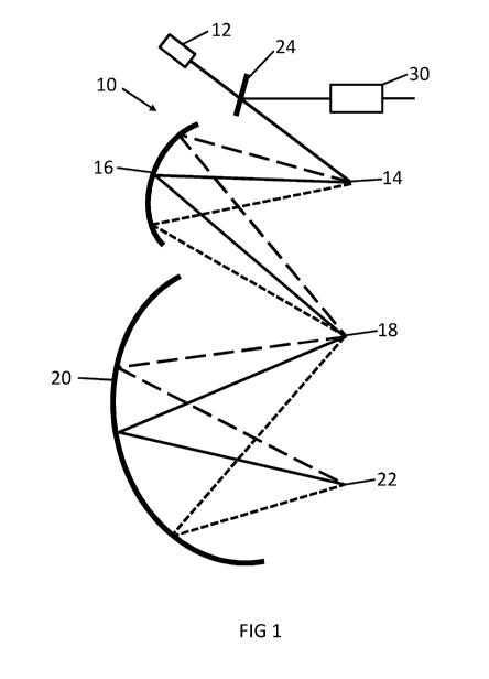
Figure 1 is a schematic representation of an ophthalmoscope according to the
first
aspect of the invention;
Figure 2 is a schematic representation of a first scan transfer element
according to the
second aspect of the invention used in the ophthalmoscope of Figure 1;
Figure 3 is a schematic representation of a top view of a fundus return light
separation
apparatus of the ophthalmoscope of Figure 1, and
Figure 4 is a flow chart of a method of defining a shape of the first scan
transfer element
of Figure 2 used in the ophthalmoscope of Figure 1.
Referring to Figure 1 an ophthalmoscope 10 comprises a light source 12, a
first scanner
14, a first scan transfer element 16, a second scanner 18, and a second scan
transfer
element 20. The light source 12 operates to produce a plurality of consecutive
beams
of incident light. The first scanner 14 is a rotating polygon and receives the
incident
light beams from the light source 12. In this embodiment, the first scanner 14
provides
a vertical scan of the incident light beams as represented by the three beams.
The first
scan transfer element 16 is a free-form static, reflective element, described
further
below. The first scan transfer element 16 has first and second focal points,
and is
positioned in the ophthalmoscope 10 such that the first scanner 14 coincides
with the
first focal point and the second scanner 18 coincides with the second focal
point, as
shown. The first scan transfer element 16 thus transfers the vertical scan of
the
incident light beams from the first scanner 14 to the second scanner 18. The
second
scanner 18 is a flat mirror driven by a stepper motor and, in this embodiment,
provides
a horizontal scan of the incident light beams. The second scan transfer
element 20 is an
aspherical mirror and has first and second focal points. It is positioned
in the
ophthalmoscope 10 such that the second scanner 18 coincides with the first
focal point
and a pupillary point of an eye 22 of a subject coincides with the second
focal point, as
shown. The second scan transfer element 20 thus transfers the horizontal scan
of the
incident light beams from the second scanner 18 through the pupillary point
and on to
the fundus of the eye 22.
CA 02960666 2017-03-07
WO 2016/038332
PCT/GB2015/052450
9
The first scanner 14, the first scan transfer element 16, the second scanner
18, and the
second scan transfer element 20 therefore operate in combination to provide a
two-
dimensional scan of incident light beams at the fundus of the eye 22. The two-
dimensional incident light scan appears to originate from an apparent point
source at
the pupillary point of the eye 22 and comprises a plurality of beams of
incident light,
each beam of incident light being incident on a different location of the
fundus of the
eye 22.
Return light from the fundus of the eye 22, in both reflectance and
fluorescence
operation modes of the ophthalmoscope 10, forms a two-dimensional scan of
return
light from the fundus of the eye 22. The two-dimensional scan of return light
comprises
a plurality of beams of return light, each beam of return light originating
from a
different location of the fundus of the eye. The two-dimensional scan of
return light
passes back through the pupilliary point of the eye 22, the second scan
transfer element
20, the second scanner 18, the first scan transfer element 16 and the first
scanner 14.
These act to descan the two-dimensional scan of the return light to provide
the plurality
of beams of return light from the first scanner 14. The plurality of beams of
return light
appears to originate from an apparent point source at the first scanner 14.
The first
scanner 14 projects each of the return light beams in a direction in which the
plurality of
beams of incident light are received from the light source 12. The beams of
return light
are separated from the incident light path by a beam splitter 24 and coupled
to
detectors (not shown). A time series of measurements from the detectors is
used to
form the two-dimensional scan of the return light and produce an image of the
fundus
of the eye 22.
Referring to Figures 1 and 2, the first scan transfer element 16 comprises a
free-form
element which has a shape defined to provide aberration correction of the
return light
from the fundus of the eye. The free-form element 16 has a shape comprising
curvature in each of first and second substantially orthogonal axes, x, y, of
the element.
The curvature along the first, y, axis is defined by an ellipse and the
curvature along the
CA 02960666 2017-03-07
WO 2016/038332
PCT/GB2015/052450
second, x, axis is defined by a pre-determined mathematical function,
comprising one or
more polynomial functions. The free-form element 16 is substantially
rectangular in
shape and the first axis, y, of the element lies at an angle to a long axis of
the
rectangular shape as shown and the second axis, x, of the element lies at an
angle to a
5 short axis of the rectangular shape as shown. The elliptical curvature
along the first
axis, y, of the free-form element 16 provides the first and second foci of the
element
with which the first and second scanners 14, 18 coincide respectively. This
shape and
positioning of the free-form element 16 provides aberration correction whilst
maintaining an apparent point source of incident light at the pupillary point
of the eye
10 22 and an apparent point source of return light at the first scanner 14.
In this embodiment. the free-form element 16 is positioned in the
ophthalmoscope 10
such that the first, y, axis of the element forms a substantially vertical
axis and the
second, x, axis of the element forms a substantially horizontal axis. It
will be
appreciated, however, that the free-form element may be positioned in the
ophthalmoscope such that the first axis of the element forms a substantially
horizontal
axis and the second axis of the element forms a substantially vertical axis.
The shape of the free-form element 16 is defined to produce aberration
correction of
each of the beams of return light at the apparent point source at the first
scanner 14
originating from different locations of the fundus. This produces beams of
return light
which, at the apparent point source at the first scanner 14, have a
substantially uniform
divergence in a direction of the beams substantially orthogonal to a direction
of travel
of the beams and substantially parallel to the second axis of the free-form
element 16
i.e., in this embodiment, a horizontal dimension of the return beams. The free-
form
element 16 corrects aberration in a horizontal dimension of each of the beams
of return
light. The aberration correction of the free-form element 16 does not result
in
aberration correction in a vertical dimension of the beams of return light.
Each of the
beams of return light has a different converging/diverging vertical dimension.
CA 02960666 2017-03-07
WO 2016/038332
PCT/GB2015/052450
11
The shape of the free-form element 16 also provides aberration correction of
each of
the beams of incident light incident on different locations of the fundus of
the eye 22.
This produces beams of incident light which, at the apparent point source at
the
pupilliary point of the eye 22, have a substantially uniform divergence in a
direction of
the beams substantially orthogonal to a direction of travel of the beams and
substantially parallel to the second axis of the free-form element 16 i.e., in
this
embodiment, a horizontal dimension of the incident beams.
Referring to Figures 1 and 3, the ophthalmoscope 10 comprises return light
detection
apparatus 30 positioned in the ophthalmoscope 10 to receive the beams of
return light
from the fundus of the eye 22 via the first scanner 14 and the beam splitter
24. The
return light detection apparatus 30 comprises a collimating lens 32, a
focussing lens 34,
which is an aspherical or spherical lens, and a slit aperture 36. The slit
aperture 36
comprises a first, long, dimension of approximately 2mm and a second, short,
dimension of approximately 250u.m.
The collimating lens 32 is used to focus the plurality of beams of return
light originating
from different locations of the fundus to produce beams of return light which
are
collimated in the direction of the light substantially orthogonal to a
direction of travel of
the light and substantially parallel to the second axis of the free-form
element 16 i.e., in
this embodiment, a horizontal dimension of the return beams. As the shaping of
the
free-form element 16 produces substantially uniform divergence of the beams of
return
light from any location of the fundus, the same lens 32 can be used to produce
collimation of each of beams of return light from each location of the fundus.
The focussing lens 34 and the slit aperture 36 are positioned after the
collimating lens
32 with respect to the path of each beam of return light, as shown. The slit
aperture 36
is positioned in a plane confocal with the fundus of the eye 22. The focussing
lens 34 is
positioned before the slit aperture 36 such that it focusses each beam of
return light at
the fundus confocal plane. In the horizontal, or width, dimension of each beam
of
CA 02960666 2017-03-07
WO 2016/038332
PCT/GB2015/052450
12
return light, parallel to the second, x, axis of the first scan transfer
element 16, the
beam is collimated. In the vertical, or height, dimension of the beam of
return light, the
beam is either converging or diverging. The focussing lens 34 focusses each
beam of
return light from the fundus to form a line of return light extending above
and below
the optical axis of the lens 34. The first, long, axis of the slit aperture 36
is positioned
substantially parallel with each line of return light, and the line of light
produced by
each beam of return light substantially passes through the slit aperture 36
and is
detected.
Return light from other structures, such as the cornea of the eye 22 and
elements of the
ophthalmoscope 10, will not be focussed by the focussing lens 34 into a line
of light and
will substantially not pass through the slit aperture 36 i.e. are
substantially filtered out.
This leads to an improvement in confocal detection of the fundus return light.
Referring to Figure 4, a method of defining a shape of the free-form first
scan transfer
element 16 of Figure 2 used in the ophthalmoscope 10 of Figure 1 is
illustrated. This
comprises constructing an optical description of a system comprising the
ophthalmoscope (40), passing a plurality of rays through the system (42),
determining
paths of the rays through the system (44), using the paths of the rays to
measure
aberration of at least some of the elements of the ophthalmoscope as a
function of
angle (46) and using the aberration measurement to determine a shape of the
free-
form element (48). The method may further provide compensation for aberrations
of a
model eye, by constructing an optical description of a system comprising the
ophthalmoscope and the model eye, passing a plurality of rays through the
system to
impinge at a plurality of angles on a surface of the model eye, determining
paths of the
rays through the system, using the paths of the rays to measure aberration of
at least
some of the elements of the ophthalmoscope and the model eye as a function of
angle,
and using the aberration measurement to determine a shape of the free-form
element.