Note: Descriptions are shown in the official language in which they were submitted.
CA 02960823 2017-03-09
WO 2016/040593 PCT/US2015/049373
SYSTEM FOR TRACKING UTILIZATION AND CONSUMPTION OF MEDICAL ITEMS IN A MEDICAL
FACILITY AND MAINTAINING A CHAIN OF CUSTODY BASED THEREON
FIELD
[0001i This invention relates to the field of medical item inventory
management. More
particularly, this invention relates to a system for sensing and recording
items that are to be
consumed or have been consumed during a medical procedure.
BACKGROUND
00021 The use of medical supplies and sterile medical devices in the provision
of health care
services is one of the most significant expenses incurred by most health care
facilities.
Depending upon the nature and complexity of the medical procedure being
performed, a large
number of supply items may be used during a medical procedure and, given the
priorities of
medical personnel involved in the procedure, the ability to track the
supplies, gather data about
supply utilization and consumption, and record that data in a useable format
can be especially
difficult. While hospitals and other health care facilities may have
sophisticated information
systems related to supply inventory management and procedure-based supply
requirements, such
systems are not able to provide consistent data analysis of supply utilization
and optimization if
the usage data is not recorded diligently.
100031 In a typical hospital, there are multiple different information systems
that are utili zed for
managing supply inventory and for insuring that the proper supplies are
provided for each
medical procedure, such as a particular surgery. In the first instance, the
hospital supply
department will typically have an inventory management system that tracks
medical supply
inventory, identifies the location of that inventory and records inventory
levels as supplies are
withdrawn for usage or replaced with new shipments of supplies or re-stocks
from previously
withdrawn but unused supplies. This inventory management system typically
tracks the location
of supplies in multiple locations throughout the hospital. In some hospitals,
this inventory
process is still a manual process.
(00M] Another common type of information system in a typical hospital that
interfaces with the
inventory management system is the Operating Room Information System (ORIS).
The typical
1
CA 02960823 2017-03-09
WO 2016/040593 PCT/US2015/049373
ORIS will provide functionality such as scheduling the operating rooms for
procedures,
identifying the type of procedure to be pertbrmed, identifying the doctor
performing the
procedure, idenfifying the assisting nurse(s), and maintaining lists of
supplies, devices and
instruments (Bills of Materials, or BOM's) that should be provided for each
procedure.
Typically, these BOM 's are specific to (I) the type of procedure being
performed and (2) the
physician performing the procedure. These BOM's are often maintained in a form
known as
Doctor Preference Cards.
100051 It is common for the hospital inventory management system to interface
with the ORIS in
order to insure that the right supplies, devices and instruments are in stock
and available for the
upcoming scheduled medical procedures. Prior to each case, the BOM for a given
procedure and
physician is used to pull the appropriate supplies, devices and instruments
for that case.
[0006i During the case, supply, device and instrument utilization for the
procedure should be
logged and unused items returned to inventory. When properly logged, useful
data about supply
utilization is captured and communicated to both the ORIS system and the
inventory
management system. That data can subsequently be used to capture cost
information for the
procedure, update the inventory system, prompt necessary re-orders and, as the
data for multiple
procedures and physicians is accumulated, to analyze supply cost and
utilization information for
optimization of BOM's to reduce supply waste and identify supply cost savings
opportunities.
100071 If accurate information about the consumption of supplies, devices and
instruments is not
captured, then the ability to identify savings opportunities or to accurately
bill for all consumed
supply items is lost. It is difficult to insure that this logging step is
performed accurately and
consistently, since the medical personnel are primarily concerned with
insuring the success of the
medical procedure. Often, the medical personnel do not have time during the
procedure to
manually log information into a computer for used items that do not include
barcodes, or to scan
the barcodes of used items that have barcodes. As a result, much of the
information winds up
being lost during the turnover of the medical procedure room from one case to
another. Another
problem with inaccurately recording usage information is the possibility of
erroneously charging
for items that were not used, which can raise regulatory issues.
100081 The use of RFID tags as part of the inventory control system has
potential to facilitate the
logging of the supply consumption more accurately and efficiently.
2
CA 02960823 2017-03-09
WO 2016/040593 PCT/US2015/049373
SUMMARY
100091 in one aspect, embodiments of the invention use Radio Frequency
identification (RFID)
tags to provide the following general functions: (1) identifying medical items
or other resources
that enter a room or other space in a medical facility; (2) determining where
those medical items
or other resources came from; and (3) determining whether those medical items
or other
resources were consumed during a medical procedure performed in the room or
space.
NOM In preferred embodiments of the present invention, each item pulled for
use during a
particular medical procedure in accordance with the Bill of Materials (BOM)
for the procedure
and the physician includes an RFID tag affixed to the item or the item's outer
packaging. These
RFID tags contain appropriate inventory information regarding each item as
maintained in the
inventory control system and the Operating Room Information System (ORIS) or
other
procedure room software system. Each individual item that might be used can be
tracked
through use of the RFID tags and appropriate RFID reader technology.
100111 In preferred embodiments, each Operating Room (OR) or other medical
procedure room
has a shielded enclosure with multiple RFID antennas disposed inside.
Preferably, a waste bin or
receptacle is disposed in the shielded enclosure. This shielded enclosure and
an RFID reader
connected to the antennas may be conveniently located near the location where
the sterile
medical supplies are typically opened by the circulating nurse or other OR
personnel responsible
for setting up the OR for each procedure, such as near the OR back table. The
RFID reader is
preferably configured so as to only sense RFID tags that are inside the
enclosure and not to sense
RFID tags outside the enclosure.
100121 Some preferred embodiments include a portal containing multiple RFID
antennas
connected to an RFID reader for reading RFID tags on medial items that are
passed through the
portal. The RFID reader connected to the portal antennas is preferably
configured so as to only
sense RFID tags that are inside the portal and not to sense RFID tags outside
the portal.
Preferably, the portal is also conveniently located near the location where
the sterile medical
supplies are typically opened by the circulating nurse or other personnel
responsible for setting
up the room for each procedure. The portal may also be located in areas where
supplies are
stored outside the procedure room and at other transition locations in the
medical facility.
3
CA 02960823 2017-03-09
WO 2016/040593 PCT/US2015/049373
[0013] Once the packaging of a medical supply is opened, that item is
considered "consumed"
because the packaging has been compromised and it cannot be re-stocked. In
preferred
embodiments, as the packaging of medical supply items having RFID tags are
opened, the
packaging is dropped into the waste bin inside the shielded enclosure and the
reader reads the
RFID tags on that packaging. The RFID reader is connected to a data collection
interface, such
as an ORIS computer terminal, a tablet computer or smart phone, and the
consumption
information for each item is logged.
100141 This system provides an accurate way to track supply utilization that
does not require
additional data input steps from the OR personnel. Simply throwing the
discarded packaging
into a waste bin, which is normal procedure, allows for the RFID tagged
supplies to be registered
as consumed.
[0015i In a further preferred embodiment, a stock bin is provided. Prior to
performance of a
medical procedure, all RFID-tagged medical supply items that were pulled from
the supply room
or supply cabinet are placed in the stock bin, the stock bin is moved through
the portal or is
placed inside the shielded enclosure, and the RFID reader reads the data from
the RFID tags on
the packaging. In this manner, pre-op data regarding items pulled for use
according to a
particular BOM can be captured for a given case.
(0016) Following the conclusion of the procedure, all RFID-tagged medical
supply items that
have not been opened, which are thus eligible for re-stocking, are placed into
the stock bin, the
stock bin is moved through the portal or is placed inside the shielded
enclosure, and the RFID
reader reads the data from the RFID tags on the packaging. In this manner,
post-op data
regarding both consumption and non-consumption relative to a given BOM can be
captured for a
given case. In some embodiments, the RFID reader is connected through a data
interface into the
ORIS system or the inventory management system and the data regarding the non-
consumed
items are captured. The process preferably associates medical items (and/or
their manufacturer's
lot number) and instrument trays to specific patients in the event of a recall
or negative
occurrence that is determined post-case.
[0017i Once the pre-op data and post-op data are accurately collected, the
data can be very
useful in myriad ways. Since consumption data is accurately determined through
the sensing of
packaging in the waste bin, billing for medical items consumed in the case can
be more
4
CA 02960823 2017-03-09
WO 2016/040593 PCT/US2015/049373
accurately reflected on the patient's bill, allowing the hospital to more
accurately charge for the
procedure. If the stock bin option is included, this ensures that items pulled
for the procedure
that were detected in the pre-op scan, but were not consumed during the
procedure are properly
returned to inventory. This process also digitally tracks the movement of each
item through
various transition locations in the medical facility. This makes it possible
to identify excessive
handling of items and potential exposures to infectious patients.
(0018) More sophisticated data analysis can lead to significant cost
improvements, such as by
trending consumption and non-consumption for multiple procedures and doctors.
100191 Some preferred embodiments provide an apparatus for tracking custody of
medical items
in a supply and consumption chain, wherein each medical item has an RFID tag
attached thereto
that encodes medical item information specific to the medical item. The
medical items are
initially collected together as a shipment of medical items, and the shipment
has a packing list
that has a shipment identifier that encodes shipment identification
information specific to the
shipment. The apparatus includes first and second reading devices, first RFID
antennas, a first
RFID reader, a medical facility inventory computer, and a medical item
inventory database. The
first reading device is disposed in an area of a medical facility at which the
shipment of the
medical items is received. The first reading device reads the shipment
identifier associated with
the packing list and decodes the shipment identification information encoded
in the shipment
identifier. The first RFID antennas, which are disposed in a supply room in
the medical facility,
receive radio frequency signals emanated from the RFID tags attached to the
medical items in
the shipment after the medical items have been brought into the supply room.
The radio
frequency signals contain the medical item information encoded in the RFID
tags attached to the
medical items. The first RFID reader, which is associated with the supply room
of the medical
facility and is electrically connected to the first RFID antennas, decodes the
medical item
information contained in the radio frequency signals emanated from. the RFID
tags attached to
the medical items. The second reading device, which is associated with the
supply room of the
medical facility, reads the shipment identifier associated with the packing
list and decodes the
shipment identification information encoded in the shipment identifier. The
medical facility
inventory computer is programmed to receive the shipment identification
information, the
medical item information, a first personnel identifier that identifies a
person responsible for
receiving the shipment of medical items at the medical facility, a second
personnel identifier that
CA 02960823 2017-03-09
WO 2016/040593 PCT/US2015/049373
identifies a person responsible for placement of the medical items into
inventory at the medical
facility, and a supply room identifier that identifies the supply room into
which the medical items
are placed into inventory. The medical item inventory database associates the
shipment
identification information with the first personnel identifier, the second
personnel identifier, and
the supply room identifier. The medical facility inventory computer is
programmed to
automatically generate one or both of a first message directed to the person
responsible for
receiving the shipment of medical item.s at the medical facility and a second
message directed to
the person responsible for placement of the medical items into inventory at
the medical facility.
The generation of the first message is triggered by the shipment
identification information
becoming associated with the first personnel identifier. The second message is
triggered by the
shipment identification information becoming associated with the second
personnel identifier.
The first and second messages prompt the person to whom they are directed to
take some action
with regard to the shipment of medical items.
100201 In some embodiments, the medical item inventory database maintains a
chain of custody
of the medical items in the shipment based on cross-referencing the shipment
identification
information with the first personnel identifier and the second personnel
identifier.
(0021) In some embodiments, the apparatus includes a supply room portal having
a portal
opening and second RFID antennas having fields of view directed to the portal
opening. The
second RFID antennas receive radio frequency signals emanated from RFID tags
attached to
medical items that pass through the portal based on the medical items being
picked for removal
from the supply room to be used in a medical procedure. A second RFID reader
that is
electrically connected to the second RFID antennas decodes the medical item
information
contained in the radio frequency signals emanated from the RH D tags. The
medical facility
inventory computer is programmed to automatically associate a third personnel
identifier with
the medical item information contained in the radio frequency signals, where
the third personnel
identifier identifies a person responsible for removal of the medical items
from the supply room.
This association is triggered by the RFID tags on the medical items in the
shipment being
detected by the second RFID reader.
6
CA 02960823 2017-03-09
WO 2016/040593 PCT/US2015/049373
[0022] In some embodiments, the medical item inventory database maintains the
chain of
custody of the medical items in the shipment based on cross-referencing the
medical item
information contained in the radio frequency signals with the third personnel
identifier.
100231 in some embodiments, the medical items that have been picked for use in
a medical
procedure are placed in a transport container. The transport container
includes an RFID tag that
encodes transport container identification information. In these embodiments,
the RFD
antennas in the supply room portal receive a radio frequency signal emanated
from the RFID tag
attached to the transport container as it passes through the portal, and the
second RFID reader
decodes the transport container identification information. The medical
facility inventory
computer is programmed to automatically associate the transport container
identification
information with the medical item information of the medical items disposed in
the transport
container.
100241 In some embodiments, the apparatus includes a procedure room portal
having a portal
opening and third RFID antennas having fields of view directed to the portal
opening. The third
RFID antennas receive radio frequency signals emanated from RFID tags attached
to medical
items that pass through the procedure room portal when the medical items are
brought into a
medical procedure room to be used in a medical procedure. A third RFID reader,
which is
electrically connected to the third RFID antennas, decodes the medical item
information
contained in the radio frequency signals emanated from the RFID tags. The
medical facility
inventory computer is programmed to automatically associate a fourth personnel
identifier with
the medical item information contained in the radio frequency signals, where
the fourth
personnel identifier identifies a person responsible for the medical items
while the medical items
are in the medical procedure room. This association is triggered by the RFID
tags on the medical
items in the shipment being detected by the third RFID reader.
100251 In some embodiments, the medical item inventory database maintains the
chain of
custody of the medical items in the shipment based on cross-referencing the
medical item
information contained in the radio frequency signals with the fourth personnel
identifier.
[0026i In some embodiments, the apparatus includes a shielded enclosure
disposed in the
medical procedure room. The shielded enclosure has an internal space for
receiving wrappers of
medical items used during the medical procedure and is configured to attenuate
radio frequency
7
CA 02960823 2017-03-09
WO 2016/040593 PCT/US2015/049373
signals emanated from RFID tags disposed outside the shielded enclosure to
levels that are
substantially undetectable within the internal space. Fourth RFID antennas are
disposed within
the internal space of the shielded enclosure. The fourth MID antennas receive
radio frequency
signals emanated from RFID tags attached to the wrappers disposed within the
internal space,
which signals contain the medical item information encoded in the RFID tags. A
fourth MID
reader, which is electrically connected to the fourth RFID antennas, decodes
the medical item
information contained in the radio frequency signals emanated from the RFID
tags attached to
the wrappers disposed within the internal space. The medical facility
inventory computer is
programmed to automatically associate a patient identifier with the medical
item information
contained in the radio frequency signals, where the patient identifier
identifies a patient on which
the medical procedure was performed in the medical procedure room. This
association is
triggered by the RFID tags of the medical items in the shipment being detected
by the fourth
RFID reader.
100271 In some embodiments, the medical item inventory database maintains a
chain of custody
of the medical items in the shipment based on cross-referencing the medical
item information
contained in the fourth radio frequency signals with the patient identifier.
(0028) In some embodiments, the medical facility inventory computer is
programmed to
automatically generate a fifth message directed to patient treatment personnel
if the medical item
information indicates that the medical item is a DME medical item. The
generation of the fifth
message is triggered by the medical item information contained in the radio
frequency signals
becoming associated with the patient identifier. The fifth message prompts the
patient treatment
personnel to perform one or more of the following actions: (1) disclose
information to the patient
related to the proper use of the DME medical item; (2) input information to
verify delivery of the
DME medical item to the patient; and (3) obtain the patient's signature to
acknowledge receipt of
the DME medical item.
100291 Som.e embodiments include a medical facility exit portal having a
portal opening and
RFID antennas having fields of view directed to the portal opening. The MD
antennas receive
radio frequency signals emanated from RFID tags attached to DME medical items
that pass
through the medical facility exit portal as the DME medical items exit the
medical facility in the
custody of patients to which the DME medical items have been dispensed. An
RFID reader
8
CA 02960823 2017-03-09
WO 2016/040593 PCT/US2015/049373
decodes the medical item information contained in the radio frequency signals
emanated from
the RFID tags attached to the DME medical items. The medical facility
inventory computer is
programmed to automatically perform one or more of the following actions upon
receipt of the
medical item information contained in the radio frequency signals:
changing billing records for the patient to indicate that billing for a DME
medical item has
changed from Medicare Part A, in which the medical facility pays for rental of
the DME
medical item, to Medicare Part B, in which the patient or the patient's
insurance company
is billed for the DME medical item;
updating records in the medical item inventory database to transfer custody of
the DME
medical item from the medical facility to the patient; and
sending notifications to one or more of the patient and medical personnel
regarding follow-
up care for the patient while using the DME medial item, such notifications
including one
or more of a recommendation of a Medicare Part B healthcare provider and a
prompt for
scheduling of follow-up appointments for the patient.
100301 In some embodiments, the RFID antennas of the procedure room portal are
operable to
receive radio frequency signals emanated from RFID tags attached to medical
items that were
not used or consumed during the medical procedure and which pass through the
procedure room
portal as medical items leave the medical procedure room to be returned to the
supply room. The
medical facility inventory computer of these embodiments is programmed to
automatically
associate a fifth personnel identifier with the medical item information
contained in the radio
frequency signals, wherein the association is triggered by the RFID tags on
the medical items
leaving the medical procedure room. The fifth personnel identifier identifies
a person
responsible for the medical items until the medical items are returned to the
supply room.
100311 In some embodiments, the RFID antennas of the supply room portal are
operable to
receive radio frequency signals emanated from RED tags attached to medical
items that were
not used or consumed during the medical procedure and which pass through the
supply room
portal as the medical items reenter the supply room to be returned to stock.
The medical facility
inventory computer of these embodiments is programmed to automatically
disassociate the fifth
personnel identifier from the medical item information contained in the radio
frequency signals,
wherein the disassociation is triggered by detection of the RFID tags on the
medical items that
have been returned to the supply room.
9
CA 02960823 2017-03-09
WO 2016/040593 PCT/US2015/049373
[0032] In another aspect, embodiments of the invention provide an apparatus
for maintaining an
inventory of medical items in a medical facility, wherein each medical item
has an RFID tag
attached thereto that encodes medical item information specific to the medical
item. The
apparatus includes a shielded enclosure comprising shielded walls, a shielded
floor, and a
shielded ceiling that collectively define an internal space for storing the
medical items. A
shielded door is disposed in one of the shielded walls of the shielded
enclosure and is operable to
allow personnel to enter and exit the internal space. A door lock controller
electronically
controls a lock on the shielded door. One or more sensors associated with the
shielded door
sense an open state or closed state of the shielded door. One or more storage
bins in the internal
space hold one or more medical items. RFID antennas in the internal space
receive radio
frequency signals emanated from the RFID tags attached to the medical items in
the storage bins.
The radio frequency signals contain the medical item information encoded in
the RFID tags
attached to the medical items. An RFID reader, which is electrically connected
to the RFID
antennas, performs scans to detect RFD tags within range of the RFID antennas
and decodes the
medical item information contained in the radio frequency signals emanated
from detected RFID
tags. Preferred embodiments include a computer programmed to discontinue scans
by the RFID
reader if signals from the one or more sensors associated with the shielded
door indicate that the
shielded door is in an open state. This prevents the RFID reader from
detecting RFID tags that
are outside the shielded enclosure.
(0033i In some embodiments, the computer is programmed to cause the door lock
controller to
maintain the shielded door in a locked state while the RFID reader is
performing a scan to detect
RFID tags.
100341 In some embodiments, the computer is programmed to control the RFID
reader to
perform an RFID system calibration procedure involving a known number of RFID
tags attached
to medical items disposed in the shielded enclosure. The procedure includes:
(a) performing a scan of the RFID tags with the RFID reader set at a first
transmitter power
level;
(b) the RFID reader detecting a first number of RFID tags attached to the
medical items
disposed in the shielded enclosure;
(c) comparing the first number of RFID tags to the known number of RFID
tags;
CA 02960823 2017-03-09
WO 2016/040593 PCT/US2015/049373
(d) if the first number of RFID tags is less than the known number of RFID
tags, performing
a scan of the RFID tags with the RFID reader set at a second transmitter power
level that
is incrementally higher than the first transmitter power level;
(e) repeating steps (b) through (d) until the first number of RFID tags
equals the known
number of RFID tags; and
(0 operating the RH D reader at the second transmitter power level for
ongoing inventory
maintenance purposes.
(0035) In some embodiments, the calibration procedure includes:
(a) performing a scan of the RFID tags with the RFID reader set at a first
receiver sensitivity
level;
(b) the RFID reader detecting a first number of RFID tags attached to the
medical items
disposed in the shielded enclosure;
(c) comparing the first number of RFID tags to the known number of RFID
tags;
(d) if the first number of RFID tags is less than the known number of RFID
tags, performing
a scan of the RFID tags with the RFID reader set at a second receiver
sensitivity level
that is incrementally higher than the first receiver sensitivity level;
(e) repeating steps (b) through (d) until the first number of RFID tags
equals the known
number of RFID tags; and
(0 operating the MID reader at the second receiver sensitivity level for
ongoing inventory
maintenance purposes.
BRIEF DESCRIPTION OF THE DRAWINGS
100361 Other embodiments of the invention will become apparent by reference to
the detailed
description in conjunction with the figures, wherein elements are not to scale
so as to more
clearly show the details, wherein like reference numbers indicate like
elements throughout the
several views, and wherein:
100371 FIG. I depicts a system for sensing and recording consumption of
medical items during a
medical procedure according to an embodiment of the invention;
11
CA 02960823 2017-03-09
WO 2016/040593 PCT/US2015/049373
WM FIGS. 2A and 2B depict shielded enclosures according to embodiments of the
invention;
[0039] FIG. 3 depicts a method for sensing and recording consumption of
medical items during a
medical procedure according to an embodiment of the invention;
100401 FIG. 4 depicts a method for programming RFID tags for use on medical
items according
to an embodiment of the invention;
100411 FIGS. 5A-5C depict display screens displayed to a user of the system
while performing
the method depicted in FIG. 4 according to an embodiment of the invention;
100421 FIG. 6 depicts a method for programming RFID tags for use on storage
bins used for
carrying medical items according to an embodiment of the invention;
100431 FIGS. 7A-7C depict display screens displayed to a user of the system
while performing
the method depicted in FIG. 6 according to an embodiment of the invention;
(0044i FIG. 8 depicts a method for reading RFD tags on medical items placed in
the shielded
enclosure according to an embodiment of the invention;
10045) FIGS. 9A-9C depict display screens displayed to a user of the system
while performing
the method depicted in FIG. 8 according to an embodiment of the invention;
100461 FIG. 10 depicts a method for reading RFID tags on medical items passed
through a portal
according to an embodiment of the invention;
100471 FIGS. 11A-11B depict display screens displayed to a user of the system
while performing
the method depicted in FIG. 10 according to an embodiment of the invention;
100481 FIG. 12 depicts a method for searching for medical items having RFID
tags that have
been scanned into the system according to an embodiment of the invention;
(0049) FIG. 13 depicts a method for searching for medical items and retrieving
item data
according to an embodiment of the invention;
(0050) FIG. 14 depicts a method for system maintenance according to an
embodiment of the
invention;
12
CA 02960823 2017-03-09
WO 2016/040593 PCT/US2015/049373
[0051] FIG. 15 depicts a display screen displayed to a user of the system
while performing the
method depicted in FIG. 12 according to an embodiment of the invention;
100521 FIG. 16 depicts a display screen displayed to a user of the system
while performing the
method depicted in FIG. 13 according to an embodiment of the invention;
100531 FIG. 17 depicts a display screen displayed to a user of the system
while performing the
method depicted in FIG. 14 according to an embodiment of the invention;
100541 FIGS. 18A - 18F depict a portal according to an embodiment of the
invention;
100551 FIGS. 19 and 20 depict processes for sensing and recording utilization
of medical
resources in the performance of a medical procedure in a medical facility
according to
embodiments of the invention;
(00561 FIGS. 21 and 22 depict processes for generating alerts based on
utilization of medical
resources in the performance of a medical procedure in a medical facility
according to
embodiments of the invention;
100571 FIGS. 23, 24A, 24B and 25 depict a system for tracking medical items
through various
transition points in a supply and consumption chain according to an embodiment
of the
invention;
100581 FIG. 26 depicts an apparatus for maintaining an inventory of medical
items according to
an embodiment of the invention;
[0059] FIG. 27 depicts a computer system associated with a supply room door
according to an
embodiment of the invention;
100601 FIGS. 28 and 29 depict exemplary user interface screens generated by a
RFID label
printer application according to an embodiment of the invention;
100611 FIG. 30 depicts an exemplary printed RF1) label according to an
embodiment of the
invention; and
13
CA 02960823 2017-03-09
WO 2016/040593 PCT/US2015/049373
10062] FIGS. 31 and 32 depict exemplary user interface screens generated by
the RFID label
printer application according to an embodiment of the invention.
DETAILED DESCRIPTION
[0063] As the term is used herein, a "medical item" is an item, material,
substance, or piece of
durable medical equipment (DME) that is used or consumed during the
performance of a medical
procedure or that is dispensed to a patient to treat a medical condition or
provide comfort to the
patient. For example, sponges, gloves and drapes are medical items. A surgical
implant is
another example of a medical item. Knee braces, negative pressure wound
therapy units, blood
glucose monitors, and wheelchairs are further examples of medical items.
Medical items
comprise a subset of "medical resources." As the term is used herein, a
"medical resource" is
any item, person, piece of equipment, or space involved in providing medical
services for a
patient. For example, a gurney on which a patient lies during a surgical
procedure is a medical
resource. The doctor performing the procedure, the attending nurses, and the
patient are also
medical resources. An operating room is a medical resource.
100641 As the term is used herein, a "wrapper" encompasses all manner of
containers and
packaging, sterile or non-sterile, in which a medical item is or has been
enclosed. The term
"wrapper" also includes a label, hang tag, or other such device that may be
attached to a medical
item without completely enclosing the item. The term "wrapper" further
includes packaging for
a sterile-wrapped kit of medical items, such as a tray of implants and
supplies for use in a
surgical procedure, wherein an RFID tag is attached to the tray. Generally,
anything that may
function to associate an RFID tag with a medical item is encompassed by the
term "wrapper."
100651 Each medical item has a unique item identifier encoded in a machine-
readable code in an
RFID tag, a QR code, a bar code, or a combination thereof attached to the
medical item or its
wrapper. In some embodiments, an RFID tag and a QR code are combined in a
single label
applied to the medical item or its wrapper.
100661 In a preferred embodiment, each wrapper includes an RFID tag attached
thereto or
embedded therein. Ultra High Frequency (UHF) passive RFID tags are preferred
for this
application, as they may be interrogated from up to about 30 centimeters to
about 30 feet away.
In preferred embodiments, each RFID tag is encoded with a unique item
identification number
14
CA 02960823 2017-03-09
WO 2016/040593 PCT/US2015/049373
for the particular medical item associated with the wrapper. An item
information database 52
associates each item identification number with item-specific information,
such as the
manufacturer part number, item description, vendor, cost, Latex content,
expiration date, and
inventory location. Additionally or alternatively, the RFID tag may be encoded
with item-
specific information as set forth in Unique Device Identification (UDI)
standards set by the U.S.
Food and Drug Administration (FDA).
[0067] In some embodiments, item-specific information encoded in RFID tags on
medical items
may be used to generate alerts for medical personnel. For example, an alert
may be generated if
information encoded in an RFID tag indicates the presence of Latex in an item,
and the patient is
allergic to Latex. Also, an alert may be generated if information encoded in
an RFID tag
indicates that an item's useful lifetime has expired or if the item is from a
lot that has been
recalled by the manufacturer.
100681 As the term is used herein, a "portal" is any passageway, opening,
aperture, window,
panel, wall, doorway, hallway, pathway, or aisle in or near which one or more
RFID antennas are
mounted for sensing RFID tags that pass through or near the portal. A portal
may also be a
handheld scanning device for reading RFD tags. Several portals may be used to
track the routes
of travel and locations of medical resources throughout a medical facility or
a medical item
supplier facility.
100691 As the term is used herein, a "scan" for RPM tags refers to operations
performed by an
RFD reader to transmit signals and receive signals from RFID tags that are in
range of the R
reader and its associated antenna(s).
100701 In preferred embodiments, portals are placed at "transition locations"
within a medical
facility or a medical item supplier facility. Examples of transition locations
include supply
rooms, supply cabinets, procedure rooms, waste containers, personnel break
rooms, hallways,
shipment assembly areas, shipment loading docks, and points of entry into and
exit from the
medical facility or a medical item supplier facility.
100711 As the term is used herein, a "shipment" of medical items comprises
multiple medical
items, of the same type or different types, that are packaged together at a
supplier location and
shipped to a location at which the medical items are consumed or dispensed.
Generally, each
CA 02960823 2017-03-09
WO 2016/040593 PCT/US2015/049373
shipment includes a packing list that lists all of the medical items in the
shipment. In preferred
embodiments, each packing list has a unique shipment identifier that encodes
shipment
identification information that is specific to the shipment. The shipment
identifier may be in the
form of an RFID tag, bar code, or other encoded identifier attached to,
embedded in, or printed
on the packing list.
[0072i Sensing and Logging Consumption of Medical Items During Medical
Procedure
100731 As shown in FIG. 1, a system 10 for sensing and logging consumption of
medical items
during a medical procedure includes a shielded enclosure 12 having a space 16
that is large
enough to receive a waste bin 18. Disposed within the enclosure 12 are two
RFID antennas 14a
and 14b, such as Laird 5 x 5 inch Mini Far Field antennas (model number
S9025PLNF) having
left-hand circular polarization and operating in the 902-928 MHz frequency
range. In an
alternative embodiment, a single larger Laird antenna is used. One of the
antennas 14a is
preferably disposed at the top of the enclosure 12, with its field of view
looking downward into
the space 16. The other RFID antenna 14b is preferably disposed at the bottom
of the enclosure
12, with its field of view looking upward into the space 16. The RFID antennas
14a-14b are
electrically connected, such as via a coaxial cable, to a UHF MID tag reader
28. In a preferred
embodiment, the RFID tag reader 28 is an Impinj Speedway model R420.
[0074] Preferred embodiments of the shielded enclosure 12 are shown in FIGS.
2A and 2B,
wherein the sidewalls are depicted as transparent. The enclosure 12 is
preferably made from
0.080 inch thick sheet aluminum supported by 0.75 x 0.75 inch square aluminum
tubing (0.125
thick). The outside dimensions of the preferred embodiment are 23.5 x 22.0 x
40.75 inches.
100751 As the term is used herein, "shielded" means that the enclosure 12 is
designed to prevent
the antennas 14a-14b from receiving RFID signals from RFID tags located
outside the enclosure
12 at a signal-to-noise ratio high enough to trigger detection of those
outside RFID tags. For
purposes of this disclosure, "shielded" does not mean that absolutely all RF
energy is blocked
from entering the enclosure, as this would require unnecessary levels of
shielding.
100761 in some embodiments, an opening 24 is provided in the top of the
enclosure that is large
enough to receive wrappers or containers 20 from which medical items have been
removed. The
opening 24 is preferably a 6.75 x 13.75 inch rectangle. An aluminum cover 25
is provided over
16
CA 02960823 2017-03-09
WO 2016/040593 PCT/US2015/049373
the opening 24. The cover may be slanted as shown in FIG. 2A or more box-like
as shown in
FIG. 2B to prevent signals from escaping the enclosure 12. As shown in FIG.
2B, the enclosure
preferably includes an aluminum chute 23 around the opening 24, and an
aluminum shield 27
around the antenna 14a. These structures provide further attenuation of RFID
signals originating
outside the enclosure 12 to prevent those signals from being detected by the
antennas 14a-14b.
The waste bin 18 is positioned below the opening 24 so that wrappers 20
deposited in the
opening 24 fall into the bin 18. In a preferred embodiment, a hinged door 26
large enough to
receive the waste bin 18 is provided in a sidewall of the enclosure 12. The
door 26 is preferably
29.5 x 39.25 inch, and includes a handle/latch for securing the door in a
closed position. The
enclosure 12 is considered to be shielded when the door 26 is closed.
100771 In a preferred embodiment, the system 10 includes a portal 48 having an
opening 49 at
least large enough to receive the waste bin 18. The portal 48 is preferably
equipped with four
RFD antennas 50a-50d having fields of view looking inward into the portal
opening 49. The
RFID antennas 50a-50d are electrically connected, such as via coaxial cables,
to a UHF RFID
tag reader 46. In a preferred embodiment, the RFID tag reader 46 is an Impinj
Speedway
model R220. In some embodiments, the tag reader 46 and the tag reader 28
comprise a single
tag reader.
100781 The waste bin 18, also referred to herein as a waste tote, is
preferably a plastic container
having an open top for receiving wrappers 20. in some embodiments, an RFID tag
22 encoded
with a unique bin identification number is attached to the waste bin 18. The
database 52
associates the bin identification number with a particular procedure room to
which the waste bin
18 is assigned. Alternatively, the RFID tag 22 may be encoded with information
indicating the
procedure room to which the bin 18 is assigned.
100791 The RFID tag readers 28 and 46 are electrically connected via a local
area network
(LAN) 42 to a medical item inventory computer 31, which may be a server
computer, desktop
computer, laptop computer, tablet computer or other mobile computing device.
Alternatively,
the electrical connection between the RH D tag readers 28 and 46 and the
computer 31 is via a
Universal Serial Bus (USB) interface. The computer 31 includes memory for
storing and a
processor for executing instructions of a medical item inventory module 40. In
preferred
embodiments, the medical item inventory module 40 compiles pre-op and post-op
lists of items,
17
CA 02960823 2017-03-09
WO 2016/040593 PCT/US2015/049373
compares the lists to detect discrepancies, generates alert messages upon
detection of
discrepancies, and updates inventory records based on actual item usage.
100801 In a preferred embodiment, an Operating Room Information System (ORIS)
computer 30
is in communication with the medical item inventory computer 31 via a
communication network,
such as the LAN 42. The ORIS computer 30 is also in communication with a
hospital computer
system 32 via a communication network, such as the LAN 42. in preferred
embodiments, the
hospital computer system 32 manages medical item inventories, procedure room
scheduling,
patient records, insurance reimbursement/payment functions, and
admission/discharge/transfer
(ADT) records. The hospital computer system 32 may also include or be
connected to an
electronic data interchange server, such as a J.D. Edwards/Oracle server, that
implements
electronic commerce transactions between the hospital and medical item
suppliers.
100811 In some embodiments, the medical item inventory module 40 is a software
application
running on the computer 31. In alternative embodiments, the medical item
inventory module 40
is executed by a remote computer (outside the OR). For example, the medical
item inventory
module 40 may be implemented as "software-as-a-service" provided via the
Internet by a
medical item inventory service provider.
100821 With continued reference to FIG. 1, a preferred embodiment of the
system 10 includes a
stock bin 34, which may also be referred to herein as a transport bin,
transport container, or stock
tote. As described in more detail below, the stock bin 34 is used to transfer
medical items 38 to
be used during a medical procedure from a stock room to the procedure room,
and to transfer
unused medical items 38 from the procedure room back to the stock room. In
some
embodiments, an RFID tag 36 is attached to the stock bin 34 that is encoded
with a unique bin
identification number. In some embodiments, the database 52 associates the bin
identification
number with a particular procedure room or stock room to which the stock bin
34 is assigned.
Alternatively, the RFID tag 36 may be encoded with information indicating the
procedure room
or stock room to which the stock bin 34 is assigned.
[00831 FIG. 3 depicts a preferred embodiment of a process 100 for sensing and
recording
consumption of medical items during a medical procedure using the system
depicted in FIG. 1.
To begin the process, hospital personnel pick medical items from inventory
stock to be used
during the medical procedure (step 102 in FIG. 3). For example, the needed
items may be listed
18
CA 02960823 2017-03-09
WO 2016/040593 PCT/US2015/049373
on a Bill of Materials (BOM) for the particular type of procedure to be
performed. In some
cases, the BOM also reflects the individual preferences of particular doctors.
These types of
BOM's may also be referred to as Doctor Preference Cards. The picked items are
placed in the
stock bin 34 to be transferred to the OR.
100841 In one embodiment, the stock bin 34 containing the picked items 38 is
placed in or passed
through the portal 48 outside the procedure room (step 104) and the REED
reader 46 reads the
RFID tags on the wrappers of the items 38 in the stock bin 34 (step 106). In
some embodiments,
activation of the reader 28 is triggered manually by a person in the procedure
room using an
interface device (mouse, touchpad or keyboard) of the computer 31.
100851 The item identification numbers read from the RFID tags in the portal
48 are transferred
to the medical item inventory computer 31 where the medical item inventory
module 40
compiles a pre-op list of the items 38 in the stock bin 34 (step 108). In a
preferred embodiment,
the date/time of the compilation of the list is recorded in the medical item
inventory computer
31, along with the identification number of the stock bin 34. Other
information may be
associated with the pre-op list, such as procedure room number, doctor name,
patient name,
patient age, patient weight, patient allergies, type of medical procedure, and
case number. Once
the pre-op list is compiled, the RFID reader 28 may be deactivated (step 109)
and the stock bin
34 removed from the portal 48 (step 110).
100861 Steps 104-110 of FIG. 3 are optional and are not implemented in all
embodiments of
process 100. If these steps are not performed, the BOM for the medical
procedure may serve the
purpose of the pre-op item list.
100871 The items 38 are preferably removed from the bin 34 and arranged on a
table in the
procedure room according to the doctor's or attending nurse's preference. As
the items 38 are
used/consumed during the procedure (step 112), wrappers 20 removed from the
items 38 are
dropped through the opening 24 in the enclosure 12 where they are received
into the waste bin
18 (step 114). When the wrappers 20 enter the enclosure 12, the RFID tags on
the wrappers 20
are detected and read by the reader 28 (step 116). It will be appreciated that
a waste bin 18 is not
absolutely necessary for this process. However, the use of a waste bin 18
makes collection and
removal of the wrappers 20 easier.
19
CA 02960823 2017-03-09
WO 2016/040593 PCT/US2015/049373
(0088) The item identification numbers read from the RFID tags in the
enclosure 12 are
transferred to the medical item inventory computer 31 where the medical item
inventory module
40 compiles a post-op used-item list of the wrappers 20 (step 118). In a
preferred embodiment,
the date/time that each wrapper 20 was first detected is recorded in the list.
Also, the
identification number of the waste bin 18 (if any) and other information may
be associated with
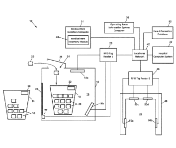
the post-op used-item list, such as procedure room number, doctor name,
patient name, type of
medical procedure, and case number. Once the post-op used-item list is
compiled, the RFID
reader 28 is deactivated (step 119) so that it will not read any other tags
when the door 26 is
opened to remove the wrappers 20 (step 120). Deactivation of the reader 28 may
be triggered by
opening the door 26 of the enclosure 12.
100891 In an alternative embodiment, the waste bin 18 remains outside the
shielded enclosure 12
during the procedure. As the items 38 are used/consumed during the procedure
(step 112),
wrappers 20 removed from the items 38 are deposited in the waste bin 18. After
completion of
the procedure, the waste bin 18 containing the wrappers 20 is placed through
the portal 48 (step
114), and the reader 28 reads the RFID tags of the wrappers 20 (step 116). The
post-op used-
item list is compiled as described in the previous embodiment (step 118).
[0090] In some embodiments, after completion of the medical procedure, all
unused items 38 are
placed back into the stock bin 34, and the stock bin 34 is passed through the
portal 48 (step 122).
The reader 46 reads the RFID tags of the unused items 38 (step 124), and a
post-op unused-item
list is compiled (step 126). The identification number of the stock bin 34 and
other information
may be associated with the post-op unused-item list, such as procedure room
number, doctor
name, patient name, type of medical procedure, and case number.
100911 Steps 122-126 of FIG. 3 are optional and are not implemented in all
embodiments of
process 100. If these steps are not performed, the post-op unused-item list
may be generated by
comparing the BOM to the post-op used item list.
100921 Various embodiments of the invention use the pre-op and post-op item
lists to implement
various advantageous inventory and billing functions. For example, the medical
item inventory
module 40 may compare the items listed in the pre-op list to the items listed
in the post-op used-
item list and the post-op unused-item list (step 128). If an item in the pre-
op list does not appear
on either of the post-op lists (step 130), this means the item was brought
into the procedure room
CA 02960823 2017-03-09
WO 2016/040593 PCT/US2015/049373
but neither the item nor its wrapper ended up in the stock bin or the waste
bin after the
procedure. In this case, an alert is generated that causes a message to appear
on a display screen
of the ORIS computer 30 or the medical item inventory computer 31 (step 132).
The alert should
prompt the procedure room personnel to investigate three possibilities that
may have caused the
discrepancy: (1) the item is unused and still in the procedure room but was
inadvertently not
placed back into the stock bin before the post-op unused-item list was
compiled, (2) the item was
used and its wrapper is still in the procedure room but the wrapper was
inadvertently not placed
in the waste bin before the post-op used-item list was compiled, or (3) the
item and/or its empty
wrapper was removed from the procedure room prior to compilation of either of
the post-op lists.
In any event, the missing item(s) or wrapper(s) should be located and the pre-
op and post-op lists
reconciled (step 134).
100931 If the comparison of the pre-op and post-op item lists indicates that
an item that appears
on either of the post-op lists is not on the pre-op list (step 136), this
means that the item or its
wrapper was present in the procedure room when the post-op lists were
compiled, but it was (1)
not brought into the procedure room in the stock bin with the other items, or
(2) brought into the
procedure room in the stock bin but was removed from the stock bin prior to
compilation of the
pre-op list. In this case, an alert is generated which causes a message to
appear on a display
screen of the computer 31 (step 138). The alert should prompt the procedure
room personnel to
investigate what may have caused the discrepancy and reconcile the pre-op and
post-op lists
(step 140).
[0094i In a preferred embodiment, once the post-op lists are complete and
reconciled, the
computer 31, the ORIS computer 30, or the hospital computer system 32 uses the
lists to update
the database 52 based on actual item usage (step 142). The hospital computer
system 32 or the
ORIS computer 30 also may use the post-op used-item list to accurately bill
the patient (or
insurance company) for the items used during the procedure (step 146). The
stock bin 34 may be
returned to the appropriate inventory stock room where the unused items 38 may
be returned to
inventory (step 144).
100951 In preferred embodiments, the hospital computer system 32 or the
Medical Item
Inventory Application 40 analyzes the post-op unused-item lists generated
during multiple
procedures of the same type and for the same doctor to determine trends in the
lack of usage of
21
CA 02960823 2017-09-09
WO 2016/040593 PCT/US2015/049373
certain medical items that are listed on BOM's (step 146). This trend data may
be used to revise
the BOM's for certain procedures/doctors. For example, if the trend data
indicates that in 90%
of hip replacement surgeries performed by Dr. 'Jones only three sponges of a
particular type are
used out of the five called for on the BOM, the BOM may be revised to call for
only three
sponges. Revisions of this sort would reduce the effort/cost associated with
returning unused
items to the stock room, and would decrease traffic in and out of the
procedure room during a
procedure which would decrease the chances of a site infection. Trend data may
also be used to
determine the optimal locations to store medical supplies and the optimal
quantities to store.
100961 FIG. 4 depicts an embodiment of a method 150 for programming RFID tags
for medical
items. While running the medical item inventory application, the user selects
the "Program
Tags" tab on the example display screen depicted in FIG. 5A (step 152). If the
user does not
know the item number of the medical item for which a tag is to be programmed
(step 154), the
user may select the "Search" button (step 156). This causes the application to
display an items
list (step 158) from which the user selects the item (step 160). The user then
enters the lot
number and expiration date (step 162) and selects the "Query Available Tags"
button (step 166).
This activates the RFID reader/writer to detect and display a number of tags
that are available for
programming (step 168). In the example of FIG. 5B, the RFID reader/writer
detected fifteen tags
available for programming. Before programming the tags with item information,
the user has an
opportunity to edit the item information (step 170). If the item information
is complete and
accurate, the user selects the "Confirm and Program" button (step 172). This
causes the RFD
reader/writer to program the available RFID tags with the item information
(step 174). The
number of tags that are successfully programmed are indicated as "Number of
Successful
Writes" as shown in FIG. 5C (step 176). The user then selects the "Continue"
button (step 178),
which causes the application to associate the newly programmed tags with the
item number in
the database 52 (step 180).
[0097] FIG. 6 depicts an embodiment of a method 190 for programming RFID tags
for bins or
totes, such as the waste bin 18 or the storage bin 34. While running the
medical item inventory
application, the user selects the "Program Totes" tab on the example display
screen depicted in
FIG. 6A (step 192). The user then enters the item number for the tote (step
194) and selects the
"Query Available Tags" button (step 196). This activates the RFID
reader/writer to detect the
number of tags that are available for programming (step 198) and display the
available number
22
CA 02960823 2017-03-09
WO 2016/040593 PCT/US2015/049373
on the display device (step 200). In the example of FIG. 7B, the RFID
reader/writer detected
three tags available for programming. If the user wishes to proceed with the
programming
process, the user selects the "Confirm and Program" button (step 204). This
causes the RFID
reader/writer to program the available RFID tags with the tote information
(step 206). The
number of tags that are successfully programmed are indicated as "Number of
Successful
Writes" as shown in FIG. 7C (step 176). The user then selects the "Continue"
button (step 208),
which causes the application to associate the newly programmed tags with non-
consumable totes
in the database 52 (step 210). The programmed tags are then attached to the
totes (step 212).
100981 FIG. 8 depicts an embodiment of a method 220 for reading RFID tags on
items dropped
into the shielded enclosure 12. While running the medical item inventory
application, the user
selects the "Dynamic Scan" tab on the example display screen depicted in FIG.
9A and selects
the scan type, such as "Intra-Op" from the dropdown list (step 222). When the
user selects the
"Begin Scan" button (step 224), the RFID tag reader 28 is activated and begins
reading the tags
of any items or item wrappers dropped into the enclosure 12 (step 226). As
shown in FIG. 9B,
information regarding all tagged items detected by the RFID tag reader is
displayed on the
display device (step 228). In this example, three tagged items or item
wrappers were detected:
(1) item 5-2711 Scalpel Stainless..., (2) item TOTE, and (3) item 712542 Drape
Hand 114 x....
If at some point during the medical procedure the waste bin within the
enclosure needs to be
emptied, the user selects the "Pause Scan" button in FIG. 9B (step 232), which
causes the
application to stop the RFID tag reader and display "Paused" on the screen as
shown in FIG. 9C
(step 234). After the full bin has been replaced with an empty bin in the
enclosure (step 236), the
user selects the "Continue" button (step 238), which causes the RFID tag
reader 28 to resume
reading the tags of any additional items or item wrappers dropped into the
enclosure 12 (step
226). When the medical procedure is complete and no more wrappers are to be
dropped into the
enclosure 12 (step 240), the user selects the "Stop Scan" button (step 242),
which causes the
RFID tag reader 28 to cease detecting RFID tags in the enclosure (step 246).
The user then
selects the "Write Scans" button (step 250) at which point the application
stores in the database
52 all the item information regarding items or item wrappers that were placed
into the enclosure
during the medical procedure (step 252).
10099] FIG. 10 depicts an embodiment of a method 260 for reading RFID tags on
items passed
through the portal 48. While running the medical item inventory application,
the user selects the
23
CA 02960823 2017-03-09
WO 2016/040593 PCT/US2015/049373
"Static Scan" tab (step 262) on the example display screen depicted in FIG.
11A and selects the
scan type, such as "OR Pre-Op" from the dropdown list (step 264). The user
then enters the case
number for the medical procedure (step 266) and selects the "Scan" button
(step 268). The
application then activates the RFID tag reader 28, which begins reading the
tags of any items or
item wrappers within the field of view the antennas in the portal opening 49
(step 270). When
the user pushes a tote containing RFID-tagged items through the portal opening
49 (step 272),
the RFID tag reader 46 reads the tags of the items in the tote and the
application displays a list of
the items on the display device as shown in FIG. 11B (step 274). The user then
selects the
"Write Scans" button (step 278) at which point the application stores in the
database 52 all the
item information regarding items that were passed through the portal (step
280).
001001 FIG. 12 depicts an embodiment of a method 290 for viewing listings
of items
whose RFID tags have been read and entered into the database 52. While running
the medical
item inventory application, the user selects the "View Scans" tab (step 292)
on the example
display screen as depicted in FIG. 15 and chooses to search by item, by case
number or by
Electronic Product Code (EPC) (step 294). As will be appreciated by one
skilled in the art, the
EPC is a unique number that identifies a specific item in the supply chain.
When the user enters
the search criteria (such as CASE123) in the text box (step 296) and selects
the "Search" button
(step 298), the application retrieves item information from the database 52
regarding all items
scanned in association with CASE123 and displays a list of the item
information on the display
device as shown in FIG. 15 (step 300).
1001011 FIG. 13 depicts an embodiment of a method 310 for viewing listings
of items
having information stored the database 52. While running the medical item
inventory
application, the user selects the "Items" tab (step 312) on the example
display screen as depicted
in FIG. 16 and enters an item number or item keywords in the search text box
(step 314). When
the user selects the "Search" button (step 316), the application retrieves
item information
regarding all items in the database 52 and displays a list of the item
information on the display
device as shown in FIG. 16 (step 318). If the list indicates that RFID tags
have not yet been
programmed for an item (step 320), the user may select the "Program" button
(step 322) which
will cause the application to display the "Program Tags" tab (step 324).
24
CA 02960823 2017-03-09
WO 2016/040593 PCT/US2015/049373
[00102] FIG. 14 depicts an embodiment of a method 330 for performing
maintenance
tasks related to the database 52 and the LAN 42. While running the medical
item inventory
application, the user selects the "Maintenance" tab (step 332) on the example
display screen as
depicted in FIG. 17 and enters the network address of the database 52 (step
334). The user may
then select the "Test" button to test the connection to the database 52 (step
336). if the test
indicates a successful connection, the user may select the "Save" button to
store the database
address information (step 340). The "Maintenance" tab also allows the user to
test the network
connection to the RFID tag reader(s) by entering the IP address in the address
box (step 342) and
selecting the "Test" button (step 344). If the test indicates a successful
connection, the user may
select the "Save" button to store the IP address information (step 348).
1001031 Tracking Utilization of Medical Resources in Medical Facility
[00104] Various embodiments described herein provide systems for sensing
RFID tags
attached to various medical resources at various transition locations
throughout a medical
facility, for tracking routes of movement of the medical resources based on
the sensing of the
RFID tags, for detecting relationships between medical resources based on
sensing their RFID
tags at the same transition locations during overlapping time periods, for
analyzing utilization of
the medical resources, and for developing utilization profiles. For example,
FIG. 19 depicts an
embodiment of a process 400 for analyzing the utilization of two different
m.edical resources
based on sensing (or not sensing) their RFID tags at two different transition
locations within a
medical facility. The process 400 involves attaching RFID tags to medical
resources (step 402),
disposing RFID-sensing portals at various transition locations within the
medical facility (step
404), reading medical resource information from the RFID tags using the
portals (step 406 and
412), and decoding the medical resource information to identify the medical
resources (step 408
and 414) and determine various characteristics of the resources as described
in more detail
below.
[00105] For exam.ple, with continued reference to FIG. 19, a first
medical resource is
detected at a first transition location at a time T1 (step 410) and at a
second transition location at
a time 12 (step 416). Based on these detections, the system determines that
the first medical
resource travelled from the first transition location to the second transition
location between
CA 02960823 2017-03-09
WO 2016/040593 PCT/US2015/049373
times TI and T2 (step 418). Based on this route of travel and the times of
detection, the system
creates a utilization profile for the first medical resource (step 420).
[00106] A second medical resource is detected at the first transition
location at a time T3
(step 422), which may be less than, greater than, or equal to time TI. The
second medical
resource is again detected at the first transition location at a time 14 (step
426), which is occurs
after time T3 (T4 > T3). There is no detection of the second medical resource
at the second
transition location between times T3 and 14 (step 424). Based on these
detections, the system
determines that the second medical resource travelled from the first
transition location back to
the first transition location between times T3 and T4õ and did not travel to
the second transition
location (step 428). Based on this route of travel and the times of detection,
the system creates a
utilization profile for the second medical resource (step 430).
[00107] In the example of FIG. 19, the first transition location may be an
entrance/exit
door of a medical procedure room PR1 within a medical facility, the second
transition location
may be a waste container WC I within the medical procedure room :PM õ the
first medical
resource may be a first medical item that was picked to be used during a
medical procedure MP I
in the procedure room PRI, and the second medical resource may be a second
medical item that
was picked to be used during the same medical procedure MP1 in the procedure
room PR!.
Based on the detections described above, the system determines that the first
medical item
entered the medical procedure room PR I (first transition location) at time
TI, and it or its
wrapper was deposited in the waste container WC1 (second transition location)
at time T2.
Based on this route of travel, the system creates a utilization profile
indicating that the first
medical item was used or consumed during the medical procedure MP 1. Also
based on the
detections described above, the system determines that the second medical item
entered the
medical procedure room PR! (first transition location) at time 13, exited the
medical procedure
room PR .1 (first transition location) at time 14, and was not deposited in
the waste container
WC I (second transition location). Based on this route of travel, the system
creates a utilization
profile indicating that the second medical item was brought into the medical
procedure room
PR 1, but was not used during the medical procedure M Pl.
1001081 FIG. 20 depicts an embodiment of a process 440 for analyzing the
utilization of
three different medical resources based on their RFID tags being sensed (or
not sensed) at two
26
CA 02960823 2017-03-09
WO 2016/040593 PCT/US2015/049373
different transition locations within a medical facility. The process 440
involves reading medical
resource information from RFID tags attached to three medical resources ¨ a
first medical item, a
doctor, and a patient using portals at the entrance/exit of a procedure room
PR1 and on a waste
container WC I (step 442 and 448), and decoding the medical resource
information to identify
the medical resources (step 444 and 450) and determine various characteristics
of the resources.
As in the previous example, the system determines that the first medical item
entered the medical
procedure room PR1 at time TI, and it or its wrapper was deposited in the
waste container WC1
at time T2 (step 454). Based on this route of travel, the system creates a
utilization profile
indicating that the first medical item was used during the medical procedure
MP I (step 456).
[00109] With continued reference to FIG. 20, the system detects the doctor
DI entering
the medical procedure room PR1 at time 13 which may be less than, greater
than, or equal to
time T1 (step 458). The doctor D1 is detected leaving the medical procedure
room HU at time
14 which is greater than Ti and T3 (step 460). Based on this route of travel,
the system creates a
utilization profile indicating that the doctor DI was involved in a medical
procedure MPI in the
procedure room PR1 between times T3 and T4 (step 464). In preferred
embodiments, the
utilization profile for the doctor D1 indicates that the first medical item
was consumed or used
during a medical procedure MP1 performed by the doctor D1. In some
embodiments, the
utilization profile for the first medical item also indicates that the first
medical item was
consumed or used during a medical procedure MP1 performed by the particular
doctor DI.
[00110] With continued reference to FIG. 20, the system detects the
patient P1 entering
the medical procedure room PR1 at time 15 which may be less than, greater
than, or equal to
time T1 (step 466). The patient PI is detected leaving the medical procedure
room HU at time
16 that is greater than Ti and T5 (step 468). Based on this route of travel,
the system creates a
utilization profile indicating that the patient PI was involved in a medical
procedure MP I in the
procedure room PR1 between times 15 and 16 (step 470). In preferred
embodiments, the
utilization profile for the patient P1 also indicates that the first medical
item was consumed or
used during the medical procedure MP1 performed on the patient PI by the
particular doctor DI.
In some embodiments, the utilization profile for the first medical item also
indicates that the first
medical item was consumed or used during the medical procedure MP I performed
on the
particular patient P1. In some embodiments, the utilization profile for the
doctor DI also
27
CA 02960823 2017-03-09
WO 2016/040593 PCT/US2015/049373
indicates that the first medical item was consumed or used during the medical
procedure MP1
performed on the particular patient P1.
[00111] Generating Alerts Based on Utilization of Medical Resources in
Medical Facility
[00112] FIG. 21 depicts a preferred embodiment of a process 480 for
generating an alert
based on utilization of medical resources in the performance of a medical
procedure in a medical
facility. This process 480 analyzes the utilization of two different medical
resources based on
sensing their RFID tags at the same transition location within the medical
facility. The process
480 involves reading medical resource information from RFID tags attached to
the two medical
resources ¨ a first medical item and a patient PI ¨ using portals at the
entrance/exit of a
procedure room PR1 (step 482), and decoding the medical resource information
to identify the
medical resources (step 484) and to determine various characteristics of the
resources. For
example, the medical resource information decoded at step 484 may indicate
whether the first
medical item contains a potential allergenic, such as Latex, and whether the
patient P1 is allergic
to any drugs or substances, such as Latex. Using the decoded information, the
system detects
that the first medical item entered the medical procedure room PR! (step 486)
at a certain time
and that the patient P1 entered the medical procedure room PRA at a certain
time (step 492). If
the first medical item contains a substance to which the patient P1 is
allergic, and the first
medical item and the patient Pi are in the procedure room PR .1 simultaneously
(steps 488, 494
and 496), the system generates an alert informing personnel in the procedure
room PRI of the
potential for a harmful allergic reaction (step 498). This alert may be
audible (siren) and visible
(strobe lights) in the procedure room, and it may be sent via electronic
messaging to other
personnel within the medical facility to give notice of the situation. In
preferred embodiments,
the occurrence of such an event is also reflected in the utilization profile
of the patient P1.
[00113] In some embodiments, the system generates a potential allergic
reaction alert if an
RFID reader portal at the doorway of a supply room detects a medical item
leaving the supply
room that was picked for use during a medical procedure involving a patient
that is allergic to a
substance in the medical item. This detection could also be made by any RFID
reader portal at
any transition location between the supply room and the medical procedure
room.
[00114] FIG. 22 depicts a preferred embodiment of another process 500 for
generating an
alert based on utilization of medical resources in the performance of a
medical procedure in a
28
CA 02960823 2017-03-09
WO 2016/040593 PCT/US2015/049373
medical facility. This process 500 analyzes the utilization of two different
medical resources
based on sensing their RFID tags at the same transition location within the
medical facility. The
process 500 involves reading medical resource information from MD tags
attached to the two
medical resources ¨ a first medical item and a patient PI ¨ using portals at
the entrance/exit of a
procedure room PR1 (step 502), and decoding the medical resource information
to identify the
medical resources (step 504) and to determine various characteristics of the
resources. For
example, the medical resource information decoded at step 504 may indicate
that the patient PI
is infected with a highly infectious contagion, such as Methicillin-resistant
Staphylococcus
aureus (MR.SA). Using the decoded information, the system detects that the
first medical item
entered the medical procedure room PR! (step 506) at time TI and that the
patient P1 entered the
medical procedure room PR1 at a certain time (step 514). The system later
detects that the first
medical item has exited the medical procedure room PRI (step 508) at time T2.
if the first
medical item was not deposited in a hazardous waste container prior to leaving
the procedure
room PR1, and the first medical item and the patient PI were in the procedure
room PR I
simultaneously, and the patient P1 is infected with a contagion such as MRSA
(steps 510, 516,
518), the system generates an alert informing personnel in the procedure room
PR.I of a potential
for spread of a highly infectious contagion due to possible contact with the
first medical item
(step 520). This alert may be audible (siren) and visible (strobe lights) in
the procedure room.,
and it may be sent via electronic messaging to other personnel within the
medical facility to give
notice of the situation. In preferred embodiments, the occurrence of such an
event is also
reflected in the utilization profile of the first medical item. In some
situations, the determination
that the patient is infected (step 516) may be made after the procedure is
complete and the patient
has left the procedure room. In such situations, the system will generate the
alert (step 520) after
information indicating the patient's infection is entered into the patient's
record (the medical
resource information for the patient.)
[00115] Tracking Custody of Medical Items in Supply and Consumption Chain
[00116] FIGS. 23-25 depict a system for tracking medical item.s through
various transition
points in a supply and consumption chain. Unless otherwise defined herein, the
term "supplier"
generally refers to a medical item manufacturer or distributor or any other
entity that ships
medical items to a medical facility to be put into inventory. As shown in FIG.
23, each shipment
54 of medical items 38 from a supplier typically includes a packing list 56
that has a unique
29
CA 02960823 2017-09-09
WO 2016/040593 PCT/US2015/049373
shipment identifier 58 encoded in an RFID tag and/or a bar code attached to
the packing list or
attached to a container in which the medical items 38 are shipped. Upon
packing of medical
items 38 at a supplier facility for shipment (first transition point), a
unique item identifier 39
encoded in an RFID tag and/or a bar code attached to each packed medical item
38 and the
unique shipment identifier 58 are read by one or more reading devices 59 at
the supplier facility
and are cross-referenced in a supplier inventory database 60. In preferred
embodiments, the
reading devices 59 may include one or more MID tag readers and their
associated antennas and
one or more bar code readers. The one or more reading devices 59 may also read
the unique
personnel identifier 55 of the person responsible for the shipment of medical
items at the supplier
facility, which identifier may be encoded in the person's ID badge 57. In a
preferred
embodiment, the unique shipment identifier 58 is also cross-referenced in the
supplier inventory
database 60 with the unique personnel identifier 55. As the term is used
herein, a "supplier
facility" is any location at which the medical items are disposed prior to
shipment to the medical
facility, such as a manufacturer facility or a distributor facility.
[00117] Upon receipt of the shipment 54 of medical item.s at the medical
facility (second
transition point), the unique shipment identifier 58 of the packing list 56 is
read and decoded by
one or more reading devices 62, and the unique shipment identifier is stored
in the medical
facility inventory database 52 in association with a unique personnel
identifier 65 of the person
responsible for receiving the shipment of medical items at the medical
facility. In preferred
embodiments, the one or more reading devices 62 may include one or more RFID
tag readers
and their associated antennas and one or more bar code readers. The one or
more reading
devices 62 may also read the unique personnel identifier 65 of the person
responsible for
receiving the shipment of medical items at the medical facility, which
identifier may be encoded
in the person's ID badge 63.
[00118] Upon unpacking a received shipment 54 of medical items and
placement into
storage bins 70 in a supply room 68 at the medical facility (third transition
point), the unique
shipment identifier 58 and the unique item identifier 39 on each medical item.
38 is read and
decoded by one or more reading devices 66 in the supply room 68, and the
unique item identifier
39 of each medical item 38 is stored in association with a unique supply room
identifier in the
inventory database 52 for the medical facility. The supply room 68 may also be
referred to
herein as a "vault" and it may be electromagnetically shielded as depicted in
FIG. 26 and
CA 02960823 2017-03-09
WO 2016/040593 PCT/US2015/049373
described in more detail hereinafter. In preferred embodiments, the one or
more reading devices
66 in the supply room 68 may include one or more RFID tag readers and their
associated
antennas and one or more bar code readers. In preferred embodiments, the
inventory database
52 also cross-references the unique item identifiers 39 with a unique
personnel identifier 69 of
the person responsible for placement of the medical items into inventory at
the medical facility,
which identifier may be encoded in the person's ID badge 67.
[00119] As shown in FIG. 24A, upon pulling medical items 38 from the
supply room
storage bins 70 to be used in a medical procedure, examination or test, or to
be otherwise
dispensed to a patient (fourth transition point), the unique item identifier
39 on each medical item
38 is read and decoded by a portal reading device 41 in the supply room, and
the unique item
identifier of each medical item is stored in the inventory database 52 in
association with a unique
bill of material (BOM) identifier 73 of the BOM 74 for the
procedure/exam/test. In a preferred
embodiment, the unique item identifiers 39 and BOM identifier 73 are cross-
referenced in the
database 52 with a unique personnel identifier 75 of the person removing the
medical items from
the supply room, which identifier may be encoded in the person's ID badge 71.
At this point, the
medical items may be in a transport bin 34 or other container 34.
[00120] Upon delivery of the medical items 38 to a procedure room,
examination room, or
test room in the medical facility (fifth transition point), the unique item
identifier 39 on each
medical item is read and decoded by a portal reading device 48 in or at the
entrance to the
procedure/exam/test room, and the unique item identifier of each medical item
is stored in the
inventory database 52 in association with a unique procedure/exam/test room
identifier and a
unique personnel identifier 49 of a person accepting delivery in the
procedure/exam/test room.
The unique personnel identifier 49 may be encoded in the person's ID badge 47.
[00121] In an alternative embodiment depicted in FIG. 24B, upon pulling
the medical
items 38 from the supply room storage bins 70 to be used in a medical
procedure, examination or
test, or to be otherwise dispensed to a patient (fourth transition point), the
unique item identifier
39 on each medical item 38 is read and decoded by a portal reading device 41
in the supply
room, and the unique item identifier of each medical item is stored in the
inventory database 52
in association with a transport bin identifier 77 of the transport bin 34 used
to transport the items
to a procedure/exam/test room. The unique item identifiers 39 and transport
bin identifier 77 are
31
CA 02960823 2017-03-09
WO 2016/040593 PCT/US2015/049373
preferably cross-referenced in the database 52 with the unique personnel
identifier 75 of the
person removing the medical items from the supply room, which identifier may
be encoded in
the person's ID badge 71. In this embodiment, the transport bin 34 may contain
medical items
38 that are to be used in the treatment of several different patients in the
medical facility. In this
case, the unique item identifiers 39 will become associated with a particular
patient only after the
medical items 38 are delivered to a particular procedure/exam/test room in
which the patient is
being treated.
1001221 As shown in FIG. 25, upon dispensing the medical items 38 to a
patient or
otherwise consuming the medical items during a procedure or test performed on
the patient in the
procedure/exam/test room (sixth transition point), the unique item identifier
39 on the packaging
20 of each used medical item is read and decoded by a reading device 28
associated with the
waste bin 18 in the procedure/exam/test room, and the unique item identifier
of each medical
item is stored in the inventory database 52 in association with a unique
patient identifier.
1001231 The medical items 38 that are delivered to the procedure/exam/test
room but not
used or consumed during the medical procedure are preferably passed through
the portal 48, and
the reader 46 reads the RFID tags of the unused items 38. In a preferred
embodiment, the item
identification information encoded in those RFID tags is cross-referenced in
the database 52 with
a unique personnel identifier of the person responsible for removing the
unused medical items
from the medical procedure room and transporting the items to the supply room
for restocking,
which identifier may be encoded in the person's ID badge.
1001241 Medical items 38 in the transport bin 34 that are not delivered to
a
procedure/exam/test room preferably remain associated in the database 52 with
the identifier of
the person who originally removed the items from the supply room. When the
unused items
have been returned to the supply room and their RFID tags are read by the RED
reader 41 in the
supply room, their identifiers automatically become disassociated with the
person who removed
the items from the supply room. Those items also are once again recorded in
the database 52 as
being present in the supply room.
1001251 At each transition point, a prompt may be automatically generated
to remind the
responsible personnel to scan the unique item identifier 39 on each medical
item 38 so that the
information will be entered into the inventory database 52, or to remind the
responsible
32
CA 02960823 2017-03-09
WO 2016/040593 PCT/US2015/049373
personnel to take other action as may be necessary based on the location and
status of the
medical items 38. These prompts may be visual or audible.
[00126] In this preferred embodiment, the inventory database 52 maintains
a chain of
custody for each item 38 through each transition point (and for each shipment
54 of items
between the first and second transition points) and keeps records of the
personnel responsible for
each item or shipment at each location at any particular time.
[00127] At some transition points, individual medical item information may
not be
specifically recorded, although bulk information associated with the packing
list 56 will be
recorded. When the medical items are dispensed to the subsequent transition
point, the unique
item identifiers 39 may recovered and the unique item identifier information
can be
automatically associated with the dispensing activity where unique item
identifier information
was previously not recorded.
[00128] Although a particular sequence of transition points is described,
transition points
could consist of any handling point along the supply chain for a medical item
from manufacturer
to patient.
[00129] In further embodiments, each transition point is defined by the
type of location.
Each type of location may have a set of characteristics associated with that
location type that
trigger certain action prompts when the medical items are associated with that
particular location
type in the database 52. For example, when the shipment 54 of medical items is
received at a
supply room 68, such as by scanning the identification information on a
packing list 56, the
supply room identification equipment may prompt the inventory management
personnel to place
the products in the appropriate product storage location, initiate an RFID
scan of the room to
identify the medical items present in the room and subsequently present
information to the
inventory management personnel to determine if the room inventory, as updated,
reconciles with
the packing list.
[00130] In another example, when the RFD reader 48 in a
procedure/examination room
detects in the room a medical item that is considered to be Durable Medical
Equipment,
Prosthetics, Orthotics and Supplies (DMEPOS, also collectively referred to
herein simply as
"DME"), and it also detects a patient identification number encoded in an RFID
tag associated
33
CA 02960823 2017-03-09
WO 2016/040593 PCT/US2015/049373
with a particular patient in the room, the procedure room computer 30 may
generate action
prompts based on association of the DME item with the patent. For example, the
procedure
room computer 30 may prompt the treating personnel to disclose to the patient
certain
information related to the proper use of the DME item, to input information to
verify the delivery
of the DME item to the patient, or to obtain the patient's signature to
acknowledge receipt of the
DME item. In some embodiments, custody of a DME item passes from the treating
personnel to
the patient only after the patient has entered a digital signature on a tablet
computer or other
similar interface device. In a situation in which an old or used DME item is
detected in the
room, and the patient is supposed to receive a new item, the system may
generate a notification
to treating personnel that the old/used item should go back to hospital stock
and a new item
should be dispensed to patient.
1001311 In some embodiments, the exits of the hospital or other medical
facility are
transition points at which networked RFID tag readers are positioned. When a
just-dispensed
DME item is detected at any of these exit transition points, the medical item
inventory computer
31 triggers a billing change event to cause the billing for the DME item to
change from Medicare
Part A, in which the medical facility pays for rental, to Medicare Part B, in
which the patient or
the patient's insurance company is billed for the item. This exit event may
also cause the
medical item inventory computer 31 to update the chain of custody for the DME
item to indicate
a transfer of possession from the medical facility to the patient. Such an
exit event may also
trigger the sending of notifications to the patient and medical personnel
regarding follow-up care
for patient using the DME item, such as notifications recommending a Part B
healthcare provider
and prompting the scheduling of follow-up appointments.
[00132] Medical Item Supply Room
[00133] FIG. 26 depicts a functional block diagram of features of a
medical item supply
room 68 according to a preferred embodiment. Within the supply room 68 are one
or more
storage bins 70 in which medical items 38 are stored until they are needed for
treatment of a
patient. As the term is used herein, a "storage bin" is any storage structure
in or on which
medical items may be stored, including but not limited to a container, shelf,
drawer, hanger, or
cabinet. One or more RFID antennas 72 are directed toward the storage bins 70
to detect RFID
tags on medical items 38 stored therein. The antennas 72 are electrically
connected to one or
34
CA 02960823 2017-03-09
WO 2016/040593 PCT/US2015/049373
more RFID tag readers 66 that are in communication with the medical facility
network 42. In
some embodiments, a supply room computer 64 is provided to allow personnel in
the supply
room 68 to access medical item inventory information over the network 64.
[00134] In some embodiments, the supply room 68 has RF shielding 76 in the
walls, floor
and ceiling to prevent detection of RFID tags that are outside the supply
room. RFID shielding
76 may also be provided in gaskets around the edges of the door frame and in a
door sweep on
the bottom of the door.
[00135] In some embodiments, a computer 78 is built into the door 74 of
the medical item
supply room 68. As shown in FIG. 27, this computer 78 preferably includes a
processor 80, a
touch screen display 82, keypad 84, biometric sensor 86 such as a fingerprint
reader or retinal
scanner, and a code reader 90, such as an RFID reader, barcode reader or
magnetic stripe reader,
for reading identification information of personnel seeking access to the
supply room and
decoding the unique personnel identifiers encoded personnel ID badges. In a
preferred
embodiment, the processor 80 interfaces with one or more sensors 85 that sense
whether the door
74 is in an open state or a closed state and/or whether the door is locked or
unlocked.
[00136] The computer 78 may also interface with a door lock controller 88
to allow or
deny access to the room based on the identity of the person seeking access and
based on ongoing
activities in the room. For example, if another person is in the room entering
items into
inventory, the computer may be programmed to not allow access so as not allow
outside RED
signals into the room and interfere with the ongoing inventory activity. The
computer 78 may
also be programmed to keep the door locked while an RFID scan is taking place,
whether or not
anyone is in the room. The computer 78 may also be programmed to deactivate
the RFID reader
66 inside the room when the door is open so that no RFID tags on items outside
the room will be
detected.
[00137] In some embodiments, the supply room computer 64 or the computer
78 controls
the RFID tag reader(s) 66 to perform an RFID antenna calibration procedure.
This procedure
may involve placing a known number of RFID-tagged items in various different
storage bins 70
in the supply room 68 with the RFID tag reader 66 initially deactivated. The
computer 64 then
activates the RFID tag reader 66 at a first relatively low transmitter power
level and the number
of tags detected is noted. if not all the tags present in the room were
detected, the transmitter
CA 02960823 2017-03-09
WO 2016/040593 PCT/US2015/049373
power level is increased by a small amount to a second power level that is
greater than the first
power level and the number of tags detected is noted. This procedure is
repeated until all tags
are detected, and the lowest transmitter power level at which all tags were
detected is stored as
the optimum operational level. This general procedure could also be performed
by starting at a
relatively high transmitter power level at which all tags are detected and
then stepping down in
power until not all of the tags are detected.
[00138] Some embodiments provide for printing information regarding a
medical item on
an RFID label and electronically encoding the information in the label. After
loading RFID
labels into an RFID label printer and calibrating the printer, a print utility
application is executed
on a user computer that is networked with the RFID label printer. An exemplary
user interface
screen generated by the printer utility application is depicted in FIG. 28.
From this screen, the
user clicks on the "Search for Item" button, at which point the printer
utility application
generates the user interface screen depicted in FIG. 29. The user types in a
part description (i.e.,
"glove") or a manufacturer product code in the "Search Text" field and clicks
the "Search"
button. Alternatively, the user may type in a manufacturer name in the
"Manufacturer Search"
field and click the "Search for Manufacturer" button. At this point the
printer utility application
generates the user interface screen depicted in FIG. 31, which lists all items
having "glove" in
the item description. The user clicks on one of the listed items to select it,
at which point the
printer utility application generates the user interface screen depicted in
FIG. 32. The user then
enters the quantity, lot number, serial number, and expiration date in the
corresponding fields
depicted in FIG. 32, and clicks on the "Print" button. An example of a printed
RFID label is
depicted in FIG. 30. The user then inspects the printed RFID label to confirm
that the correct
information has printed and that it is properly aligned. In a preferred
embodiment, if
"VOIDVOIDVOID" is printed on the label, the user should repeat the printer
calibration steps.
[00139] The foregoing description of preferred embodiments for this
invention have been
presented for purposes of illustration and description. They are not intended
to be exhaustive or
to limit the invention to the precise form disclosed. Obvious modifications or
variations are
possible in light of the above teachings. The embodiments are chosen and
described in an effort
to provide the best illustrations of the principles of the invention and its
practical application, and
to thereby enable one of ordinary skill in the art to utilize the invention in
various embodiments
and with various modifications as are suited to the particular use
contemplated. All such
36
CA 02960823 2017-03-09
WO 2016/040593 PCT/US2015/049373
modifications and variations are within the scope of the invention as
determined by the appended
claims when interpreted in accordance with the breadth to which they are
fairly, legally, and
equitably entit ed.
37