Note: Descriptions are shown in the official language in which they were submitted.
CA 2960900 2017-03-16
275401
DEVICE FOR APPLICATION OF COMPOSITE MATERIALS
BACKGROUND
[0001] The field of the disclosure relates generally to a device for applying
materials to
a surface, and more particularly, to a device for applying composite materials
to a surface.
[0002] Many known methods are used for automating the fabrication of composite
parts
such as Automated Fiber Placement (AFP), which uses large spools of either dry
fibers or
pre-impregnated fibers. The material is placed onto a tool surface, such as an
airframe for
a helicopter, typically by a manipulator such as a multi-axis robotic arm.
Known AFP
methods are limited for use with materials that can be packaged in large
spools and
unwound by the manipulator. However, some known Ceramic Matrix Composite (CMC)
materials and Polymer Matrix Composite (PMC) materials are not available in
large spools
due to current manufacturing limitations. Placing these composite materials
onto a tool
surface using conventional AFP machines is not feasible because of the
unavailability of
these composite materials in spools.
BRIEF DESCRIPTION
[0003] In one aspect, a device for the placement of material on a surface is
provided. The
device includes a housing, a motor coupled to the housing, and a driving
component
coupled to the housing and powered by the motor. The device further includes
at least one
guide chute defining a guide channel with the driving component. The device
further
includes a layup roller coupled to the housing adjacent the guide channel. The
layup roller
includes a roller surface and the guide channel is configured to discharge a
quantity of
material to the roller surface. The layup roller is configured to deposit the
material onto
the surface.
[0004] In another aspect, a device for the placement of material on a surface
is provided.
The device includes a housing, an actuator coupled to the housing, a suction
arm coupled
to the actuator, and a linear guide coupled to the housing and the suction
arm. The device
1
CA 2960900 2017-03-16
275401
further includes a suction head coupled to the suction arm. The actuator is
configured to
translate the suction arm along a vertical axis defined normal to the tool
surface. The linear
guide is configured to avoid translation motion of the suction arm along a
lateral axis and
a longitudinal axis, the lateral axis and the longitudinal axis being defined
orthogonal to
each other and to the vertical axis. The suction head is configured to couple
to the material
and remove the material from a first position away from the surface and place
the strip at
a second position on the surface.
[0005] In yet another aspect, a method of adhering a material to a surface
using a device
is provided. The device includes a motor and a drive belt powered by the
motor. The
device further includes a passive belt opposing the driving belt, the passive
belt and driving
belt defining a belt channel. The device further includes at least one guide
chute, the guide
chute and drive belt defining a guide channel. The device further includes a
layup roller
adjacent the guide channel. The method includes positioning the material into
the guide
channel, driving the drive belt such that the material moves from the belt
channel to the
guide channel to a position adjacent to the layup roller, and translating the
device along a
plane parallel to the surface such that the material is adhered to the tool
surface.
DRAWINGS
[0006] These and other features, aspects, and advantages of the present
disclosure will
become better understood when the following detailed description is read with
reference to
the accompanying drawings in which like characters represent like parts
throughout the
drawings, wherein:
[0007] FIG. 1 is a front plan view of an exemplary automated material delivery
device;
[0008] FIG. 2 is an enlarged perspective view of the automated material
delivery device
shown in FIG. 1 and taken within area 2;
[0009] FIG. 3 is a perspective view of an exemplary embodiment of a strip
holder for use
with the automated material delivery device shown in FIG. 1;
2
CA 2960900 2017-03-16
275401
[0010] FIG. 4 is a cross-sectional view of the automated material delivery
device shown
in FIG. 1 taken along line 4-4;
[0011] FIG. 5 is a perspective view of the automated material delivery device
shown in
FIG. 1 further including an in-situ cutter;
[0012] FIG. 6 is a perspective view of the automated material delivery device
shown in
FIG. 1 further including an optical heater;
[0013] FIG. 7 is a perspective view of the automated material delivery device
shown in
FIG. 1 further including a liquid spray nozzle; and
[0014] FIG. 8 is an enlarged perspective view of the automated material
delivery device
shown in FIG. 1 taken within area 8.
[0015] Unless otherwise indicated, the drawings provided herein are meant to
illustrate
features of embodiments of this disclosure. These features are believed to be
applicable in
a wide variety of systems comprising one or more embodiments of this
disclosure. As
such, the drawings are not meant to include all conventional features known by
those of
ordinary skill in the art to be required for the practice of the embodiments
disclosed herein.
DETAILED DESCRIPTION
[0016] In the following specification and the claims, reference will be made
to a number
of terms, which shall be defined to have the following meanings.
[00 17] The singular forms "a", "an", and "the" include plural references
unless the
context clearly dictates otherwise.
[0018] "Optional" or "optionally" means that the subsequently described event
or
circumstance may or may not occur, and that the description includes instances
where the
event occurs and instances where it does not.
3
CA 2960900 2017-03-16
275401
[0019] Approximating language, as used herein throughout the specification and
claims,
may be applied to modify any quantitative representation that could
permissibly vary
without resulting in a change in the basic function to which it is related.
Accordingly, a
value modified by a term or terms, such as "about", "approximately", and
"substantially",
are not to be limited to the precise value specified. In at least some
instances, the
approximating language may correspond to the precision of an instrument for
measuring
the value. Here and throughout the specification and claims, range limitations
may be
combined and/or interchanged; such ranges are identified and include all the
sub-ranges
contained therein unless context or language indicates otherwise.
[0020] As used herein, the terms "processor" and "computer" and related terms,
e.g.,
"processing device", "computing device", and "controller" are not limited to
just those
integrated circuits referred to in the art as a computer, but broadly refers
to a
microcontroller, a microcomputer, a programmable logic controller (PLC), an
application
specific integrated circuit, and other programmable circuits, and these terms
are used
interchangeably herein. In the embodiments described herein, memory may
include, but
is not limited to, a computer-readable medium, such as a random access memory
(RAM),
and a computer-readable non-volatile medium, such as flash memory.
Alternatively, a
floppy disk, a compact disc ¨ read only memory (CD-ROM), a magneto-optical
disk
(MOD), and/or a digital versatile disc (DVD) may also be used. Also, in the
embodiments
described herein, additional input channels may be, but are not limited to,
computer
peripherals associated with an operator interface such as a mouse and a
keyboard.
Alternatively, other computer peripherals may also be used that may include,
for example,
but not be limited to, a scanner. Furthermore, in the exemplary embodiment,
additional
output channels may include, but not be limited to, an operator interface
monitor.
[0021] Further, as used herein, the terms "software" and "firmware" are
interchangeable,
and include any computer program stored in memory for execution by personal
computers,
workstations, clients and servers.
4
CA 2960900 2017-03-16
275401
[0022] As used herein, the term "non-transitory computer-readable media" is
intended to
be representative of any tangible computer-based device implemented in any
method or
technology for short-term and long-term storage of information, such as,
computer-
readable instructions, data structures, program modules and sub-modules, or
other data in
any device. Therefore, the methods described herein may be encoded as
executable
instructions embodied in a tangible, non-transitory, computer readable medium,
including,
without limitation, a storage device and a memory device. Such instructions,
when
executed by a processor, cause the processor to perform at least a portion of
the methods
described herein. Moreover, as used herein, the term "non-transitory computer-
readable
media" includes all tangible, computer-readable media, including, without
limitation, non-
transitory computer storage devices, including, without limitation, volatile
and nonvolatile
media, and removable and non-removable media such as a firmware, physical and
virtual
storage, CD-ROMs, DVDs, and any other digital source such as a network or the
Internet,
as well as yet to be developed digital means, with the sole exception being a
transitory,
propagating signal.
[0023] The automated material delivery device described herein facilitates the
fabrication
of a part for an apparatus separate from the automated material delivery
device. The
automated material delivery device facilitates the fabrication of the part by
laying down
thin strips of material on a tool surface. The tool surface includes, for
example and without
limitation, engine parts, blades, vanes, nozzles, shrouds, and liners. Laying
down strips
using the device and methods described herein facilitates a greater degree of
control and
flexibility in making the part. The parts, once manufactured, have a wide
array of industrial
applications, such as use in the aircraft industry to manufacture structural
components.
Thin strips are capable of adapting and contouring to complex geometries on a
tool surface
and reduce the possibility of developing wrinkles in the composite fibers of
the strips.
Further, thin strips improve material utilization by decreasing the amount of
waste of raw
composite materials. The device described herein facilitates the automation of
laying strips
on the tool surface, while also improving the quality of the part and the
consistency of the
surface of the part.
CA 2960900 2017-03-16
275401
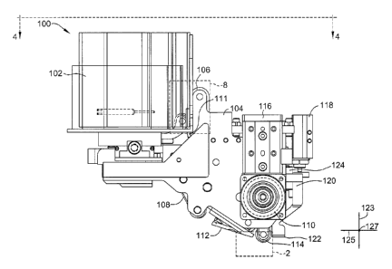
[0024] FIG. 1 is a front plan view of an exemplary automated material delivery
device
100. Device 100 includes a cartridge 102 coupled to belt housing 104. A
driving
component 106 and a passive component 108 are driven by motor 110 at least
partially
within belt housing 104. In the exemplary embodiment, driving component 106 is
a driving
belt 106, and opposed component 108 is a passive belt 108. In alternative
embodiments,
driving component 106 is any suitable component that enables device 100 to
function as
described herein, and includes, but is not limited to, rollers, belts, and
belts with suction
holes for improved gripping. In alternative embodiments, passive component 108
is any
suitable component that enables device 100 to function as described herein,
and includes,
but is not limited to, rollers, belts, and belts with suction holes for
improved gripping.
[0025] In the exemplary embodiment, as explained in more detail below, as
driving belt
106 translates, driving belt 106 passes through first guide chute 111, also
described herein
as a first guide surface, and second guide chute 112, also described herein as
a second guide
surface. A layup roller 114 is coupled to belt housing 104 and is positioned
opposite
actuator 116, which selectively translates layup roller 114 toward a tool
surface 117 (shown
in FIG. 2). In the exemplary embodiment, device 100 further includes a first
linear actuator
118 coupled to belt housing 104, and a suction arm 120 coupled to linear
actuator 118,
which enables a suction head 122 at the distal end of suction arm 120 to
selectively engage
strips 121 of a ply material located in a separate tray (not shown) via
movement along a
vertical axis 123. Device 100 further includes a second linear actuator 124,
also described
herein as linear guide 124, coupled to belt housing 104 and suction arm 120,
which enables
suction head 122 to selectively engage strips 121 as explained further herein.
In alternative
embodiments, first guide chute 111 and second guide chute 112 are any suitable
surfaces
that enable strips 121 to be guided into position while reducing friction
between guide
surface 111, 112 and strip 121, including, but not limited to, a roller, a
belt, and an air
bearing.
[0026] FIG. 2 is an enlarged perspective view of a portion of automated
material delivery
device 100 (shown in FIG. 1) taken within area 2. In the exemplary embodiment,
strip 121,
is bent and positioned onto tool surface 117 and compressed to tool surface
117 by layup
6
CA 2960900 2017-03-16
275401
roller 114. Strip 121, also known as short tape, is a substantially
rectangular piece of
material. In the exemplary embodiment, strip 121 includes a Ceramic Matrix
Composite
(CMC) material or a Polymer Matrix Composite (PMC) material. In alternative
embodiments, strip 121 is any suitable shape and includes any suitable
material that enables
device 100 to function as described herein, including, but not limited to,
parcels of material
that otherwise would not be characterized as strips.
[0027] FIG. 3 is a perspective view of an exemplary embodiment of a strip
holder 129
for use with automated material delivery device 100 (shown in FIG. 1). More
specifically,
strip holder 129 is coupled to cartridge 102. Strip holder 129 is configured
to hold a
plurality of strips 121 coupled to strip holder 129 circumferentially around
an outer surface
of strip holder 129. Strip holder 129 is configured to rotate inside cartridge
102 and is
configured to discharge one strip 121 at a time toward first guide chute 111,
similar to the
operation described below. In alternative embodiments, strip holder 129 has
the shape of
a tape roller such that strips 121 are held within the volume of strip holder
129, and not just
on the exterior of strip holder 129. In other alternative embodiments, in the
absence of
strip holder 129, cartridge 102 is configured to discharge at least one strip
121 toward first
guide chute 111.
[0028] FIG. 4 is a cross-sectional view of automated material delivery device
100 taken
along line 4-4. Cartridge 102 either includes strip holder 129 (shown in FIG.
3), or includes
a plurality of strips 121 (shown in FIG. 2) inside cartridge 102 independent
of a mechanism
such as strip holder 129. Regardless, a nip roller 130 engages with one strip
121 at a time,
and positions each strip 121 into a channel 160, also referred to herein as a
guide channel,
defined by driving belt 106 and first guide chute 111. When strip holder 129
(shown in
FIG. 3) rotates to position a strip 121 into channel 160, nip roller 130 is
disengaged from
belt 106 to provide enough space between nip roller 130 and belt 106. Once
strip holder
129 positions a strip 121 into channel 160, nip roller 130 engages on driving
belt 106 to
nip strip 121 between nip roller 130 and belt 106. In the exemplary
embodiment, nip roller
130 is translated by a linear actuator (not shown), such as but not limited to
a linear
electromagnetic motor, pneumatic cylinder, or hydraulic cylinder, to engage
and disengage
7
CA 2960900 2017-03-16
275401
nip roller 130 with belt 106 to control a pushing force, allowing strip 121 to
move with belt
106 when belt 106 translates. Driving belt 106, also described as tape
delivery belt 106 or
a feeding belt 106, is driven by motor 110 and translates in a direction 140
about pulleys
142, 144, and 146. A tensioner 148 induces tension on driving belt 106.
Opposed belt 108,
also described as corner belt 108, is also driven by motor 110 and rotates in
a direction 150
about pulleys 152 and 154. In the exemplary embodiment, motor 110 is an
electric motor.
In alternative embodiments, motor 110 is any suitable motor that enables
device 100 to
function as described herein.
[0029] Driving belt 106 and first guide chute 111 define channel 160 for
strips 121 to
move from cartridge 102 along driving belt 106 toward second guide chute 112.
Strips 121
move along driving belt 106 from channel 160 into a channel 162 defined
between driving
belt 106 and opposed belt 108, and into a channel 164, also described herein
as a guide
channel, defined by second guide chute 112 and driving belt 106. Second guide
chute 112
is positioned at an angle relative to first guide chute 111 such that, when
strip 121 is
expelled from second guide chute 112 toward layup roller 114, strip 121
contacts a surface
166 of layup roller 114. Guide channel 164 is, therefore, configured to
discharge strip 121
to surface 166 of layup roller 114. While layup roller 114 guides strip 121
into position on
tool surface 117, actuator 116 forces layup roller 114 toward tool surface
117, compressing
strips 121 onto tool surface 117 as layup roller 114 rotates in a direction
168. Layup roller
114 exerts a substantially constant pressure on strips 121, which enhances the
ability of
device 100 to adapt to the contours of tool surface 117. Layup roller 114,
therefore, is
configured to deposit strip 121 onto tool surface 117. The guided lay-down of
strip 121
serves to control both the positioning of strip 121 onto tool surface 117 and
the adhering
of strip 121 to tool surface 117. This process reduces waste by strategically
placing strips
121 onto useful portions of tool surface 117 and not onto non-useful portions
of tool surface
117, such as regions to be removed by a lathe or mill or other machining
equipment, which
reduces the amount of excess material that is wasted. Once strip 121 has
advanced to a
position underneath layup roller 114, driving belt 106 is either passively
idle to allow layup
roller 114 to continue to advance strip 121 itself or driving belt 106 is
actively controlled
8
CA 2960900 2017-03-16
275401
to reduce a potential shearing force on strip 121 when strip 121 contacts
layup roller 114.
In the exemplary embodiment, actuator 116 is a pneumatic actuator. In
alternative
embodiments, actuator 116 is any suitable actuator that enables device 100 to
function as
described herein.
[0030] In alternative embodiments, strips 121 are not assembled into cartridge
102, but
instead are assembled in a stack (not shown), away from device 100. In further
alternative
embodiments, strips 121 are located away from device 100 on an accessible
surface, such
as, but not limited to, a tray (not shown) of a dispersed plurality of strips
121. Further, in
alternative embodiments, one or more strips 121 are any suitable shape and
include any
suitable material that enables suction head 122 to function as described
herein, including,
but not limited to, parcels of materials that otherwise would not be
characterized as strips.
Suction arm 120 is actuated along axis 123 by actuators 118 and linear guide
124 to position
suction head 122 over a strip 121 or a stack of strips 121. Suction head 122
then applies a
suction or partial vacuum to at least one strip 121. Actuator 118 and suction
head 122 are
therefore configured to translate arm 120 to translate along vertical axis 123
defined normal
tool surface 123. Linear guide 124 allows arm 120, and therefore suction head
122, to
translate along axis 123, which avoids the movement of strip 121 along the
orthogonal
plane defined by axes 125 and 127. Linear guide 124, therefore, is configured
to avoid
translational motion of arm 120 along lateral axis 125 and longitudinal axis
127. Each strip
121 can then be picked up from the stack, also referred to herein as a first
position, by
suction head 122 and positioned over tool surface 117, also referred to herein
as a second
position. Suction head 122 is therefore configured to couple a plurality of
strips 121 by
first removing strips 121 from a first position away from tool surface 117,
positioning strips
121 at a second position on tool surface 117, and releasing strips 121 at a
second position
on tool surface 117. Pressure can be applied to strip 121 once strip 121 is on
tool surface
117 by translating actuator 118, and therefore suction arm 120, in a plane
normal to tool
surface 117 to compress strip 121 onto tool surface 117. In an alternative
embodiment,
once strip 121 is placed onto tool surface 117 by suction head 122, layup
roller 114 is
9
CA 2960900 2017-03-16
275401
configured to compress strip 121 via actuating actuator 116 in a plane normal
to tool surface
117 to compress strip 121 onto tool surface 117.
[0031] FIG. 5 is a perspective view of automated material delivery device 100
further
including an in-situ cutter 202. In-situ cutter 202 is coupled to second guide
chute 112 and
is positioned such that a strip 121 passes through in-situ cutter 202 before
reaching layup
roller 114. Strips 121 are fed through device 100 as described above, and in-
situ cutter 202
is configured to cut strips 121 into smaller strips 121 before strips 121 are
rolled onto tool
surface 117 (shown in FIG. 2) by layup roller 114. In the exemplary
embodiment, in-situ
cutter 202 cuts strips 121 into a substantially rectangular shape. In
alternative
embodiments, in-situ cuter 202 cuts strips 121 at any suitable angle such that
the resulting
strips 121 are trapezoidal and that enables the strips 121 to be placed on
tool surface 117
by device 100 as described herein.
[0032] FIG. 6 is a perspective view of automated material delivery device 100
further
including heating device 302. Heating device 302 is coupled to second guide
chute 112
and is configured to heat at least a portion of tool surface 117 (shown in
FIG. 2) and/or a
surface of strip 121 before strip 121 is disposed on tool surface 117. The
heating of tool
surface 117 before strips 121 are rolled onto tool surface 117 adheres strips
121 more
effectively to tool surface 117. In alternative embodiments, the entire tool
surface 117 is
heated external to device 100 (not shown) before strips 121 are rolled onto
tool surface
117. In the exemplary embodiment, heating device 302 is an infrared heater or
infrared
laser. In alternative embodiments, heating device 302 is any suitable heating
device that
enables device 100 to function as described herein.
[0033] FIG. 7 is a perspective view of automated material delivery 100 further
including
spray nozzle 402. Spray nozzle 402 is coupled to second guide chute 112 and is
configured
to spray adhesion-promoting liquid from an external source (not shown) toward
tool
surface 117 to facilitate the adhesion of strips 121 to tool surface 117,
which improves the
bond between strips 121 and tool surface 117. In alternative embodiments,
spray nozzle
402 includes a liquid pressure source that delivers adhesion-promoting liquid
to spray
CA 2960900 2017-03-16
275401
nozzle 402 and an air pressure source that enables the liquid spray to form an
aerosol that
facilitates a substantially uniform distribution of adhesive onto tool surface
117. In these
embodiments, the pressures of the air source and liquid source are controlled
by a pressure
regulator and are active only during the layup process, i.e., during adhesion
of strips 121
to tool surface 117.
[0034] FIG. 8 is an enlarged perspective view of a portion of automated
material delivery
device 100 (shown in FIG. 1) taken within area 8. In the exemplary embodiment,
a sensor
502 is coupled to housing 104. Sensor 502 is configured to detect a first
strip position 504,
shown in phantom, and a second strip position 506 of strip 121 as strip 121 is
fed through
device 100. Sensor 502 is further configured to detect a change in position of
strip 121. In
the illustrated embodiment, sensor 502 detects a first strip position 504 of
strip 121 as strip
121 is engaged by nip roller 130, and a second strip position 506 of strip 121
as strip 121
is translated into channel 160 (shown in FIG. 4) by driving belt 106. In
alternative
embodiments, sensor 502 is coupled to any other portion of device 100 that
enables sensor
502 to detect a position or change in position of strip 121. In other
alternative
embodiments, sensor 502 is coupled to housing 104 to detect a position or
change of
position of a strip 121 that is external to device 100, such as the position
of a strip 121 in a
stack of strips 121. In further alternative embodiments, sensor 502 is
configured to detect
the position of strip holder 129. In other alternative embodiments, sensor 502
is not
coupled to device 100, but rather is coupled to an external surface (not
shown) to detect
position of a strip 121 relative to device 100, such as the position of a
strip 121 relative to
suction head 122. In the exemplary embodiment, sensor 502 is an optical
sensor. In
alternative embodiments, sensor 502 is a proximity sensor, or any other
suitable sensor that
enables device 100 to function as described herein.
[0035] The above described automated material delivery device overcomes
several
deficiencies associated with known devices. The device described herein
facilitates the
fabrication of a part for an apparatus separate from the automated material
delivery device.
The automated material delivery device facilitates the fabrication of the part
by laying
down thin strips of material on a tool surface. The tool surface includes, for
example= and
11
CA 2960900 2017-03-16
275401
without limitation, engine parts, blades, vanes, nozzles, shrouds, and liners.
Laying down
strips using the device and methods described herein facilitates a greater
degree of control
and flexibility in making the part. The parts, once manufactured, have a wide
array of
industrial applications, such as use in the aircraft industry to manufacture
structural
components. Thin strips are capable of adapting and contouring to complex
geometries on
a tool surface and reduce the possibility of developing wrinkles in the
composite fibers of
the strips. Further, thin strips improve material utilization by decreasing
the amount of
waste of raw composite materials. The device described herein facilitates the
automation
of laying strips on the tool surface, while also improving the quality of the
part and the
consistency of the surface of the part.
[0036] An exemplary technical effect of the methods, systems, and device
herein
includes at least one of: (a) adhering or positioning strips of composite
materials onto a
tool surface for materials that are undesirable to manufacture into spools;
(b) reducing
material waste by strategically positioning small strips of material rather
than using a larger
sheet of material and cutting away the excess; (c) reducing material waste by
only placing
the strips onto useful areas of the tool surface and not onto areas, for
example, of the tool
surface that will later be removed by a lathe or other machining equipment;
(d) reducing
manual labor involved in laying composite materials, leading to higher quality
parts and
greater accuracy in placing the strips; and (e) enhancing the ability to adapt
to the contours
of the tool surface by using a roller with constant pressure on the strips.
[0037] Exemplary embodiments of an automated material delivery device are
described
above in detail. The automated material delivery device and methods of
manufacturing or
operating such a system and device are not limited to the specific embodiments
described
herein, but rather, components of systems and/or steps of the methods may be
utilized
independently and separately from other components and/or steps described
herein. For
example, the systems, apparatus, and methods may also be used in combination
with other
types of materials, and are not limited to practice with only the composite
materials
described herein. Rather, the exemplary embodiment can be implemented and
utilized in
12
CA 2960900 2017-03-16
275401
connection with many other applications, equipment, and systems that may
benefit from
using an automated material delivery device.
[0038] Although specific features of various embodiments of the disclosure may
be
shown in some drawings and not in others, this is for convenience only. In
accordance
with the principles of the disclosure, any feature of a drawing may be
referenced and/or
claimed in combination with any feature of any other drawing.
[0039] Some embodiments involve the use of one or more electronic or computing
devices. Such devices typically include a processor, processing device, or
controller, such
as a general purpose central processing unit (CPU), a graphics processing unit
(GPU), a
microcontroller, a reduced instruction set computer (RISC) processor, an
application
specific integrated circuit (ASIC), a programmable logic circuit (PLC), a
field
programmable gate array (FPGA), a digital signal processing (DSP) device,
and/or any
other circuit or processing device capable of executing the functions
described herein. The
methods described herein may be encoded as executable instructions embodied in
a
computer readable medium, including, without limitation, a storage device
and/or a
memory device. Such instructions, when executed by a processing device, cause
the
processing device to perform at least a portion of the methods described
herein. The above
examples are exemplary only, and thus are not intended to limit in any way the
definition
and/or meaning of the term processor and processing device.
[0040] While there have been described herein what are considered to be
preferred and
exemplary embodiments of the present invention, other modifications of these
embodiments falling within the scope of the invention described herein shall
be apparent
to those skilled in the art.
13