Note: Descriptions are shown in the official language in which they were submitted.
CA 02961043 2017-03-10
WO 2016/085573 PCT/US2015/054430
PASSIVE INTEGRAL ISOLATION VALVE
[0001] This invention was made with Government support under Contract No.
DE-0000583 awarded by the Department of Energy. The Government has certain
rights in this invention.
BACKGROUND
[0002] The following pertains to the nuclear reactor arts, nuclear power
arts,
nuclear reactor safety arts, and related arts.
[0003] Existing nuclear power plants are typically light water thermal
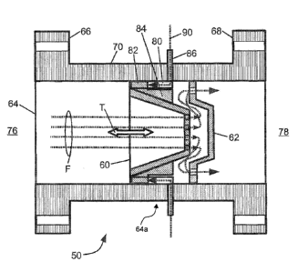
nuclear
reactors of the boiling water reactor (BWR) or pressurized water reactor (PWR)
designs.
In such a reactor, a nuclear reactor core comprising fissile material
(typically a uranium
compound such as UO2 enriched in fissile 235U) is disposed in coolant
(purified water)
contained at an operational pressure and temperature in a reactor pressure
vessel. A
nuclear chain reaction involving fission of the fissile 235U generates heat in
the nuclear
reactor core which is transferred to the coolant. In a BWR design, the heat
directly
converts coolant to steam, that is used to drive a turbine, while in a PWR
design, the
primary coolant remains in a liquid state (e.g. subcooled) and converts
secondary
coolant to steam in a steam generator ¨ this secondary coolant steam is then
used to
drive the turbine. In conventional PWR designs the steam generator is a
component
external from the reactor pressure vessel that contains the nuclear reactor.
In so-called
integral PWR designs, the steam generator is located integrally inside the
reactor
pressure vessel with (typically above) the nuclear reactor core. The integral
PWR
design advantageously reduces the number of large-diameter vessel penetrations
carrying primary coolant. In some contemplated PWR designs, these vessel
penetrations may be limited to primary coolant let-down and make-up lines, and
emergency core cooling (ECC) connections.
[0004] Safe operation of a nuclear reactor includes providing protection
against
radiological release to the environment. To this end, it is known to surround
the nuclear
reactor with a radiological containment structure typically constructed of
steel and/or
steel-reinforced concrete, and to implement safety systems, with redundancy,
to
1
CA 02961043 2017-03-10
WO 2016/085573 PCT/US2015/054430
remediate events in which reactor operation moves outside of a design
envelope. One
class of events is a loss of coolant accident (LOCA), in which reactor coolant
escapes
from a reactor pressure vessel break or, more commonly, from a break in a
large-diameter pipe that connects with the reactor pressure vessel at a vessel
penetration. A LOCA break which occurs between the vessel penetration and a
closest
pipe valve is particularly problematic, since reactor coolant loss from such a
break
continues even after the pipe valve is closed. A known solution is to provide
an integral
isolation valve (IIV) at the vessel penetration. An IIV comprises a valve
built into a
flange that connects with the pressure vessel. Since the IIV is integrated
directly into the
vessel penetration, closing the IIV ensures stoppage of reactor coolant loss
at the
LOCA break. Some IIV designs are disclosed in Malloy III et al., U.S. Pub. No.
2013/0272478 Al published Oct. 7, 2013, and in Malloy III et al., U.S. Pub.
No.
2013/0294567 Al published Nov. 7, 2013.
[0005] An IIV protecting the make-up line can be constructed as a check
valve (or
two check valves in series to provide redundancy) that is oriented to prevent
flow of
coolant out of the nuclear reactor. A check valve(s) is suitable because the
make-up
coolant flows into the reactor vessel. On the other hand, an IIV protecting
the let-down
line is more difficult. This is because the let-down coolant flows out of the
reactor, so
that a check valve design would prevent normal let-down operation.
Accordingly, IIV
designs for the let-down line typically employ a motor-operated valve.
BRIEF SUMMARY
[0006] In some embodiments described herein as illustrative examples, a
valve
assembly is configured for connection to a vessel penetration of a reactor
pressure
vessel of a nuclear reactor. The valve assembly comprises: a flange configured
to
connect with the vessel penetration; a valve body disposed inside the flange
or
arranged to protrude from the flange into the vessel penetration when the
flange is
connected with the vessel penetration; a valve comprising a valve seat and a
movable
valve member, the valve disposed inside the valve body with the movable valve
member positioned so that pressure inside the reactor pressure vessel urges
the
movable valve member against the valve seat to close the valve; and a plenum
defined
2
CA 02961043 2017-03-10
WO 2016/085573 PCT/US2015/054430
between the valve body and the movable valve member and having an inlet. The
plenum is configured such that pressurization of the plenum via the inlet
urges the
movable valve member away from the valve seat to open the valve. In
embodiments in
which the valve body is disposed inside the flange, it may be formed
integrally with the
flange, or separate from the flange and mounted inside the flange. The plenum
may
comprise a plurality of plenum regions arranged around the movable valve
member,
with the movable valve member including protrusions extending into the plenum
regions. The plenum regions may be slots arranged around the movable valve
member
and aligned with the direction of travel of the movable valve member. The
valve
assembly preferably does not include a valve actuator.
[0007] In some embodiments described herein as illustrative examples, a
system
for protecting a vessel penetration of a nuclear reactor pressure vessel of a
nuclear
reactor includes a valve assembly as set forth in the immediately preceding
paragraph
having its flange connected with the vessel penetration, and further includes
a valve
assembly control line comprising a fluid line connected with the inlet of the
plenum of
the valve assembly, and a pilot valve disposed on the valve assembly control
line. The
system may further include a reactor coolant inventory and purification system
(RCIPS)
including a make-up line supplying make-up coolant water to the reactor
pressure
vessel, with the valve assembly control line connected with the make-up line.
In such an
embodiment, the valve assembly may be connected to a let-down line of the
RCIPS to
remove let-down coolant water from the reactor pressure vessel.
[0008] In some embodiments described herein as illustrative examples, a
valve
assembly is configured for connection to a vessel penetration of a reactor
pressure
vessel of a nuclear reactor. The valve assembly comprises a flange configured
to
connect with the vessel penetration, and a valve disposed inside the flange or
arranged
to protrude from the flange into the vessel penetration when the flange is
connected
with the vessel penetration. The valve includes a valve seat and a movable
valve
member positioned so that pressure inside the reactor pressure vessel urges
the
movable valve member against the valve seat to close the valve. The valve
assembly
further includes a plenum having an inlet via which the plenum can be
pressurized to
apply pressure to the movable valve member that urges the movable valve member
3
CA 02961043 2017-03-10
WO 2016/085573 PCT/US2015/054430
away from the valve seat to open the valve. In one illustrative configuration,
the flange is
a spool flange including spaced apart first and second flange lips connected
by a hollow
channel, with the valve is disposed inside the spool flange. In some
embodiments the
valve assembly further includes a cylindrical valve body mounted on the
flange, with the
cylindrical valve body containing the valve, and the cylindrical valve body
sized to insert
coaxially into a vessel penetration comprising a cylindrical bore passing
through a wall
of the reactor pressure vessel when the flange is connected with the vessel
penetration.
The plenum may be defined in part by a surface of the movable valve member.
The
valve assembly preferably does not include a valve actuator.
[0009] In some embodiments described herein as illustrative examples, a
system
includes a nuclear reactor comprising a reactor pressure vessel having a
vessel
penetration and a nuclear reactor core including fissile material contained in
a lower
portion of the reactor pressure vessel, a valve assembly as set forth in the
immediately
preceding paragraph having its flange connected with the vessel penetration, a
valve
assembly control line comprising a fluid line connected with the inlet of the
plenum of
the valve assembly, and a pilot valve disposed on the valve assembly control
line. The
system may further include a reactor coolant inventory and purification system
(RCIPS)
including a let-down line connected with the vessel penetration via the valve
assembly
to remove let-down coolant water from the reactor pressure vessel. The RCIPS
may
further include a make-up line supplying make-up coolant water to the reactor
pressure
vessel, in which the make-up line is also connected to the valve assembly
control line to
pressurize the plenum of the valve assembly with make-up coolant water from
the
make-up line. The system may further include a radiological containment
structure
including a reactor cavity in which is disposed the lower portion of the
reactor pressure
vessel that contains the nuclear reactor core, with the valve assembly located
closer to
the reactor cavity than the pilot valve. For example, the valve assembly may
be
disposed inside the reactor cavity and the pilot valve disposed outside of the
reactor
cavity.
4
CA 02961043 2017-03-10
WO 2016/085573 PCT/US2015/054430
BRIEF DESCRIPTION OF THE DRAWINGS
[0010] The invention may take form in various components and arrangements
of
components, and in various process operations and arrangements of process
operations. The drawings are only for purposes of illustrating preferred
embodiments
and are not to be construed as limiting the invention. This disclosure
includes the
following drawings.
[0011] FIGURE 1 diagrammatically shows a nuclear reactor and a portion of
the
surrounding radiological containment structure including the reactor cavity,
along with a
reactor coolant inventory/purification system (RCIPS) having make-up and let-
down
lines protected by integral isolation valves (IIV's) as disclosed herein.
[0012] FIGURE 2 diagrammatically shows an illustrative embodiment of the
IIV
protecting the let-down line of FIGURE 1 with the valve in its open position
(permitting
let-down coolant flow).
[0013] FIGURE 3 diagrammatically shows the IIV of FIGURE 2 with the valve
in
its closed position (preventing coolant loss from the reactor via the let-down
line).
[0014] FIGURE 4 diagrammatically shows another illustrative embodiment of
the
IIV protecting the let-down line of FIGURE 1.
DETAILED DESCRIPTION OF THE PREFERRED EMBODIMENTS
[0015] It is recognized herein that existing motor-driven integral
isolation valve
(IIV) designs for the let-down line have certain deficiencies. The motor
driving the IIV
must respond and operate quickly in order to isolate a pipe break on the let-
down line.
The motor also takes up space proximate to the nuclear reactor, and may also
disrupt
reactor thermal insulation in the area proximate to the IIV. In addition, the
motor must be
robust and reliable in the presence of high temperature and high radiation
levels
adjacent to the reactor vessel.
[0016] In IIV designs disclosed herein, a valve mounted in the IIV flange
or
protruding from the flange into the vessel penetration has its movable valve
member
positioned so that pressure inside the reactor pressure vessel urges the
movable valve
member against the valve seat to close the valve. The disclosed IIV designs
further
CA 02961043 2017-03-10
WO 2016/085573 PCT/US2015/054430
include a plenum having an inlet. When the plenum is pressurized by a fluid,
the
pressure inside the plenum urges the movable valve member away from the valve
seat
to open the valve. In one suitable design, the plenum comprises a plurality of
plenum
regions, such as slots oriented parallel with the direction of travel of the
movable valve
member, and the movable valve member includes protrusions that extend into the
slots
so that pressurized fluid in the plenum slots presses against the protrusions
to urge the
movable valve member away from the valve seat to open the valve.
[0017] In these IIV designs, the valve is open whenever the pressure in the
plenum is high enough to impose an opening force that is larger than the
closing force
applied by pressure in the reactor pressure vessel. It follows that the IIV
will close under
two conditions: (1) the plenum pressure is removed or reduced to a level that
is unable
to keep the valve open, or (2) the pressure inside the pressure vessel rises
to a level
sufficient to overcome the applied plenum pressure and close the valve (this
is a vessel
overpressurization situation in which other, dedicated pressure relief valves
and/or
emergency core cooling, i.e. ECC, systems are activated). Pressure in the
plenum can
be controlled by a remote pilot valve anywhere on the control line feeding
fluid into the
plenum. Because loss of pressure in the plenum results in a failsafe closure
of the IIV,
a break on the control line cannot generate a loss of coolant accident (LOCA).
[0018] If the source of pressurized fluid to the control line is lost, the
IIV will again
close, providing failsafe operation. In some disclosed embodiments, this
source of
pressurized fluid is the make-up line of a reactor coolant inventory and
purification
system (RCIPS). Connecting the control line of the IIV to the make-up one of
the RCIPS
provides a convenient pressurization source already located inside the
radiological
containment. This arrangement also ensures that the IIV will close upon onset
of any
RCIPS failure mode that causes depressurization of the make-up line. Another
advantage of using the make-up line as the fluid source for the control line
is that if the
plenum is leaky so that fluid from the plenum can leak into the flow stream of
the IIV,
this merely introduces purified coolant water into the flow stream.
[0019] In the illustrative embodiments presented herein, the disclosed IIV
designs
are presented in the context of protecting a let-down line of the RCIPS, which
is a
typical contemplated application. However, it will be appreciated that the
disclosed IIV
6
CA 02961043 2017-03-10
WO 2016/085573 PCT/US2015/054430
designs are suitably applied to protect any vessel penetration that may carry
coolant
water out of the pressure vessel. The disclosed IIV designs are also
contemplated for
use in protecting vessel penetrations such as the make-up line that
exclusively carry
coolant into the pressure vessel, although for such applications a simpler
check valve
IIV design may be more cost-effective.
[0020] With reference to FIGURE 1, a nuclear reactor 10 comprises a reactor
pressure vessel 12 containing various components including a nuclear reactor
core 14
comprising fissile material. The nuclear reactor core 14 is shown in phantom
to
diagrammatically indicate its location in the lower portion off the pressure
vessel 12 ¨ as
the reactor core is contained inside the lower portion of the pressure vessel
12 it is
actually occluded from view. In typical commercial light water reactor
designs, the
nuclear reactor core 14 comprises fuel rods containing UO2 in which the
uranium is
enriched in the fissile 235U isotope (typically enriched to a level of 5% or
less in
commercial nuclear reactors, although higher enrichment is contemplated), and
fuel
rods are typically oriented vertically and held in a spaced array by spacer
grid
components (details not shown). During normal operation of the nuclear reactor
10, the
reactor pressure vessel 12 is filled with (primary) coolant water that is kept
at a design
operational pressure and temperature due to thermal energy generated by a
nuclear
chain reaction in the reactor core 14 balanced by heat sinking provided by
circulating
the coolant water through a heat sink. The heat sink mechanism may, for
example, be a
steam generator in the case of a pressurized water reactor (PWR) design, or
direct
boiling of the coolant in the pressure vessel with the steam piped to drive a
turbine in
the case of a boiling water reactor (BWR) design. The illustrative PWR design
is an
integral PWR design in which the steam generator is disposed inside the
pressure
vessel 12 (internal steam generator not shown in FIGURE 1); in a more
conventional
PWR design the steam generator is an external component connected with the
pressure vessel by large-diameter piping. Other components not shown in FIGURE
1
may also be contained in the pressure vessel 12, such as a central riser or
other coolant
circulation control, control rods and associated drive mechanisms (which may
alternatively be located outside of the pressure vessel), heating elements and
spargers
in an internal pressurizer at the top of the pressure vessel 12 to provide
pressure control
7
(alternatively, an external pressurizer may be connected via suitable piping),
and so
forth. The illustrative PWR 10 includes external reactor coolant pump (RCP)
units
whose motors 16 are located externally near the top of the reactor pressure
vessel 12,
but other internal or external RCP configurations are contemplated, as well as
alternative "natural circulation" reactor designs in which coolant circulation
is driven by
heat generated in the reactor core. In the case of a BWR, the pressure vessel
may
suitably contain steam handling components (dryers, et cetera). These are
merely
illustrative examples, and it is to be understood that the disclosed IIV
designs are
suitably employed in conjunction with substantially any type of nuclear
reactor that
contains pressurized coolant. As a further example, the disclosed IIV designs
are
contemplated for use with a heavy water reactor in which the coolant is heavy
water (i.e.
deuterium) and the reactor core includes UO2 that is typically less enriched
with 235U or
may even be unenriched uranium (having natural abundance of about 0.7% 235U).
[0021]
With continuing reference to FIGURE 1, the nuclear reactor 10 is
contained in a radiological containment structure 20, which is typically a
steel or
steel-reinforced concrete structure surrounding the nuclear reactor 10. For
illustrative
purposes, only a lower portion of the radiological containment structure 20 is
diagrammatically shown in FIGURE 1 using dashed lines. The illustrative
radiological
containment structure 20 includes a reactor cavity 22 in which is disposed the
lower
portion of the reactor pressure vessel 12 that contains the nuclear reactor
core 14. In
the event of a loss of coolant accident (LOCA) or other event producing
excessive
heating of the nuclear reactor core 14, the reactor cavity 22 can be flooded
from water
in a refueling water storage tank (RWST, not shown) located inside the
containment
structure 20 to assist in cooling. Although radiation shielding including
neutron shields
are typically provided around the reactor core, a high concentration of
neutrons is
typically generated by the reactor core 14 outside the containing lower
portion of the
reactor pressure vessel 12 during normal operation of the nuclear reactor 10.
As a
consequence, the gap between the pressure vessel 12 and the walls of the
reactor
cavity 22 is a relatively high radiation environment, and the radiation level
decreases
with increasing elevation above the top of the reactor cavity 22.
8
Date Recue/Date Received 2022-07-15
CA 02961043 2017-03-10
WO 2016/085573 PCT/US2015/054430
[0022] During normal operation of the nuclear reactor 10, adjustments are
made
to the coolant water inventory inside the pressure vessel 12. To this end, a
reactor
coolant inventory and purification system (RCIPS) 30 includes a purified
reactor coolant
inventory 32 external to the reactor pressure vessel 12. A make-up line 34
provides a
source of purified make-up coolant water at a pressure sufficient for
injection into the
pressure vessel 12. Because the coolant in the pressure vessel 12 is
maintained at an
operational reactor pressure P
- reactor, the make-up line 34 suitably provides a pressure
head "make¨up via suitable pumping (not shown) that is higher than the reactor
pressure
Preactor so that the make-up coolant water can be injected into the pressure
vessel 12
against the internal pressure P
reactor = Make-up valves 36 control delivery of make-up
purified coolant water to the reactor pressure vessel 12 via a make-up line
vessel
penetration that is optionally protected by an integral isolation valve (IIV)
38. Because
the make-up line 34 delivers the make-up coolant water into the nuclear
reactor
pressure vessel 12, the make-up line IIV 38 can be suitably constructed as a
check
valve that permits flow into the reactor pressure vessel 12 but blocks flow
out of the
reactor pressure vessel 12. Advantageously, the make-up line IIV 38 is a
passive check
valve that does not include a motor or other valve actuator, and accordingly
the
make-up line IIV 38 can be placed inside the reactor cavity 22 as shown, or
near the top
of the reactor cavity, which is a high radiation and heat environment.
[0023] The RCIPS 30 also includes a let-down line 44 to remove let-down
coolant
water from the reactor pressure vessel 12. Let-down valves 46 control removal
of
let-down coolant water from the reactor pressure vessel 12 via a let-down line
vessel
penetration that is optionally protected by an integral isolation valve (IIV)
50. Because
the let-down line 44 removes let-down coolant from the pressure vessel 12, the
let-down
line IIV 50 cannot be a check valve since the check valve would prevent normal
let-down operation. A conventional solution is to employ an active valve as
the let-down
IIV. As already noted, however, this approach is problematic. The motor or
other
actuator driving the active valve must respond and operate quickly in order to
isolate the
let-down line 44 in the event of a break. The motor or other valve actuator
also takes up
space proximate to the nuclear reactor 10, and may disrupt reactor thermal
insulation.
In addition, in the illustrative example in which the let-down line is located
inside the
9
CA 02961043 2017-03-10
WO 2016/085573 PCT/US2015/054430
reactor cavity or near the top of the reactor cavity, the motor or other valve
actuator
must be robust and reliable in the presence of the high temperature and high
radiation
level in this area.
[0024] In embodiments disclosed herein, the let-down IIV 50 is a valve
assembly
50 that is normally kept closed by the pressure P
- reactor inside the reactor pressure
vessel 12, and is opened by application of pressure to a plenum within the
valve
assembly 50 applied via a valve assembly control line 52. A pilot valve 54 on
the control
line 52 enables the valve assembly 50 to be closed by valving off this
pressure. In the
illustrative example of FIGURE 1, the valve assembly control line 52 is
connected to the
make-up line 34 to provide the pressure to the plenum.
[0025] With reference now to FIGURES 2 and 3, an illustrative embodiment of
the valve assembly 50 is shown in its open state (FIGURE 2) and in its closed
state
(FIGURE 3). The illustrative valve assembly 50 of FIGURES 2 and 3 includes a
movable valve member 60 and a valve seat 62 disposed in a flange 64. In this
illustrative embodiment the flange 64 is a spool flange including spaced apart
first and
second flange lips 66, 68 connected by a hollow channel 70, and the valve
including the
movable valve member 60 and the valve seat 62 is disposed inside the spool
flange 64.
The first flange lip 66 includes bore holes 72 or other fastening features
that enable the
first flange lip 66 to be secured in a sealed fashion to the let-down line
penetration of the
pressure vessel 12. The second flange lip 68 includes bore holes 74 or other
fastening
features that enable the second flange lip 68 to be secured in a sealed
fashion to a
coupling (not shown) to the valve assembly control line 52. Thus, the first
flange lip 66
faces the reactor pressure vessel side 76 and the second flange lip 68 faces
the control
line side 78. By comparing FIGURES 2 and 3, it is seen that the movable valve
member
moves in a direction of travel T indicated in FIGURES 2 and 3.
[0026] The valve assembly 50 further includes a plurality of plenums 80
which in
this illustrative example are shaped as plenum slots 80 arranged around the
movable
valve member 60 and aligned with the direction of travel T of the movable
valve
member 60. The movable valve member 60 includes protrusions 82 that extend
into the
slots 80. The valve member 60 also defines the containment of the plenum slots
80, in
the illustrative example of FIGURES 2 and 3 by having the protrusions 82
include lateral
extensions 84 that run parallel with the slots 80. Thus, in the illustrative
example of
FIGURES 2 and 3, each plenum slot 80 is defined by walls including a portion
of the
inner diameter of the hollow channel 70 of the spool flange 64, and by the
protrusion 82
and lateral extension 84 of the movable valve member 60. Said another way, the
plenum slots 80 are defined between the valve body 64a (which is integral with
the
spool flange 64) and the movable valve member 60. The plenum slots 80 have one
or
more inlets 86 that are connected with the valve assembly control line 52.
With reference to FIGURE 2, the open position of the valve assembly 50 is
shown. To
keep the valve open, pressurization 90 is applied from the control line 52 to
the plenums
80 via the inlets 86. With brief reference back to FIGURE 1, assuming the make-
up line
34 is pressurized, the plenum pressurization 90 is applied by opening the
pilot valve 54.
The movable valve member 60 experiences a force (acting toward the right in
the
orientation shown in FIGURE 2) equal to the reactor pressure P
- reactor times the area of
the movable valve member 60 projected along the direction of travel T, which
urges the
movable valve member 60 against the valve seat 62 to close the valve. To keep
the
valve assembly 50 in its open position depicted in FIGURE 2 contrary to this
force, the
force applied to the protrusions 82 by the plenum pressurization 90 (acting
toward the
left in the orientation shown in FIGURE 2) must be large enough to overcome
the
closing force due to reactor pressure P
- reactor = Since the pressure in the make-up line 34
is high enough to overcome the reactor pressure P
- reactor in order to force make-up
coolant into the reactor pressure vessel 12 (when the make-up valves 36 are
opened), a
sufficient force to keep the valve open is readily achieved. The travel of the
movable
valve member 60 toward the open position (that is, toward the left in the
orientation
shown in FIGURE 2) is stopped when the protrusions 82 contact the extreme
(left) end
of the plenum slots 80. With the movable valve member 60 held in this leftmost
position,
as shown in FIGURE 2, by the pressure applied to the plenums 80 via the inlets
86, a
coolant water flow F flows through openings in the movable valve member 60 and
through openings in the valve seat 62. This coolant water flow F is the let-
down flow into
the let-down line 44. It should be noted that the let-down flow F will only
flow when: (1)
the integral isolation valve assembly 50 is in its open position as shown in
FIGURE 2
and (2) the let-down valves 46 are also open to admit let-down flow
11
Date Recue/Date Received 2022-01-21
CA 02961043 2017-03-10
WO 2016/085573 PCT/US2015/054430
F to the RCIPS 30. During normal reactor operation, the plenum pressurization
90 is
maintained by keeping pilot valve 54 open, and let-down operations are
actually
controlled by the let-down valves 46. If the plenums 80 are well-sealed, then
the fluid
flow into the inlets 86 is essentially zero except during initial
pressurization of the
plenums 80 (that is, except when the pilot valve 54 is first opened). In
practice, the
sealing of the plenums 80 provided by the protrusions 82 and lateral
extensions 84 of
the movable valve member 60 may be imperfect. In this case some small leakage
flow
may be present in the control line 52. If the make-up line 34 provides the
pressurization
fluid, as in the illustrative example of FIGURE 4, this small leakage flow is
not
problematic since it combines with the main let-down flow F and comprises
purified
coolant water from the RCIPS 30.
[0028] With reference now to FIGURE 3, the closed position of the integral
isolation valve assembly 50 is described. To close the valve, the plenum
pressurization
90 is removed, which removes the (illustrative leftward) force opposing the
(illustrative
rightward) force provided by the reactor pressure P
- reactor= Now unopposed, the
(rightward) force due to the reactor pressure Prõ,tõ moves the movable valve
element
60 toward the valve seat 62 until the movable valve element 60 seats against
the valve
seat 62, as shown in FIGURE 3, to close the valve. This will occur if the
plenum
pressurization 90 is removed completely, for example by closing the pilot
valve 54. This
valve closure will also occur if the force urging the valve open due to the
plenum
pressurization 90 becomes smaller than the force urging the valve closed due
to the
reactor pressure P
- reactor' This latter event can occur if the pressure in the RCIPS make-
up line 34 drops sufficiently, or if the reactor pressure P
- reactor increases sufficiently due
to a reactor overpressurization condition.
[0029] With reference to FIGURE 4, another illustrative embodiment of the
let-down integral isolation valve assembly is shown, labeled as valve assembly
150.
The embodiment of FIGURE 4 employs a valve body 152 that is mounted on a
flange
164 and protrudes from the flange 164 into the vessel penetration of the
pressure
vessel 12 when the flange 164 is connected with the vessel penetration. The
valve
assembly 150 includes two movable valve members 160 and mating valve seats 162
to
provide redundancy. For illustrative purposes, the valve on the left in FIGURE
4 is
12
CA 02961043 2017-03-10
WO 2016/085573 PCT/US2015/054430
shown in its closed position (movable valve member 160 in its rightmost
position seated
against the valve seat 162), while the valve on the right in FIGURE 4 is shown
in its
open position (movable valve member 160 in its leftmost position away from the
valve
seat 162). Note that while most of the valves are in the valve body 152, the
valve seat
162 for the right-hand valve is in the flange 164. The valve includes plenum
slots 180
into which extensions 182 of the movable valve members 160 extend. However, in
the
embodiment of FIGURE 4, the lateral extensions 84 of the embodiment of FIGURES
2
and 3 are omitted and functionally replaced by constructing the movable valve
members
160 as cylindrical elements whose outer surfaces serve (together with the
protrusions
180) to seal the plenum slots 180. Said another way, the plenum slots 180 are
defined
between the valve body 152 and the movable valve member 160. Inlets 186 are
suitably
connected with the valve assembly control line 52 (see FIGURE 1) so that the
integral
isolation valve 150 can be kept in its open position by opening pilot valve 54
or closed
by closing pilot valve 54. In the open position, arrows FF indicate let-down
coolant flow
through the integral isolation valve assembly 150.
[0030] While the illustrative embodiments employ spool flanges, the
disclosed
integral isolation valve assemblies can be constructed using other types of
flanges. For
example, the spool flange can be replaced by a single-sided flange having a
flange lip
that is bolted to the reactor pressure vessel 12 at the vessel penetration and
on the
opposite side has a nipple or other pipe coupling for connecting to the
control line 52.
While the illustrative embodiment of FIGURE 1 employs the RCIPS make-up line
34 as
the pressurized fluid source for pressurizing the plenums 80, 180, which has
certain
advantages as described herein, it is contemplated to use another pressurized
fluid
source for this purpose. As another variant, it is contemplated to form the
plenum slots
as grooves formed into the movable valve element, so that the protrusions of
the
movable valve element are recessed into the movable valve body.
[0031] The integral isolation valve assembly 50, 150 preferably does not
include
a valve actuator. Rather, the isolation valve assembly 50, 150 is operated
remotely by
action of the pilot valve 54, which may be an active valve but can be located
away from
the high temperature, high radiation environment of the nuclear reactor 10. To
reduce
radiation exposure of the pilot valve 54, the valve assembly 50, 150 is
located closer to
13
CA 02961043 2017-03-10
WO 2016/085573 PCT/US2015/054430
the reactor cavity 22 than the pilot valve 54. In illustrative FIGURE 1, the
valve
assembly 50, 150 is disposed inside the reactor cavity 22 while the pilot
valve 54 is
disposed outside of the reactor cavity 22.
[0032] Illustrative embodiments including the preferred embodiments have
been
described. While specific embodiments have been shown and described in detail
to
illustrate the application and principles of the invention and methods, it
will be
understood that it is not intended that the present invention be limited
thereto and that
the invention may be embodied otherwise without departing from such
principles. In
some embodiments of the invention, certain features of the invention may
sometimes be
used to advantage without a corresponding use of the other features.
Accordingly, all
such changes and embodiments properly fall within the scope of the following
claims.
Obviously, modifications and alterations will occur to others upon reading and
understanding the preceding detailed description. It is intended that the
present
disclosure be construed as including all such modifications and alterations
insofar as
they come within the scope of the appended claims or the equivalents thereof.:
14