Note: Descriptions are shown in the official language in which they were submitted.
CA 02961188 2017-03-13
- 1 -
DESCRIPTION
TITLE OF INVENTION: PRODUCING METHOD, PRODUCING APPARATUS
AND PRODUCING EQUIPMENT LINE OF PRESS FORMED PRODUCT
TECHNICAL FIELD
[0001]
The present invention relates to a method, an apparatus and an equipment line
for producing a press formed product used in automobiles, various vehicles
other
than automobiles, home appliances, vessels, architectural materials, etc.
BACKGROUND ART
[0002]
For example, the car body of an automobile includes various structural
members (examples: floor cross members, side sills, side members, etc.). Press
formed products, which use metal sheets such as steel sheets as their starting
materials, are heavily used in the structural members. Due to the advantages
over
material rupture, shape fixability, and producing cost at the time of press
forming, in
many cases, a press formed product is obtained by performing press working on
a
metal sheet through bending forming. The press formed product has, for
example, a
channel cross-section shape or a hat-shaped cross-section shape. The press
formed
product having a channel cross-section includes a top panel part and a pair of
vertical
wall parts extending from the top panel part. The press formed product having
a
hat-shaped cross-section further includes a pair of flange parts extending
from the
respective vertical wall parts.
[0003]
FIG. 1 is a cross-sectional view schematically showing a configuration
example of a press forming apparatus that performs general bending forming. As
shown in FIG. 1, a press forming apparatus 1 is an apparatus for producing a
press
formed product having a channel cross-section or a hat-shaped cross-section.
FIG.
1 illustrates the case of producing a press formed product having a hat-shaped
cross-
section (see a dashed line in FIG. 1). The press forming apparatus 1 includes
a
CA 02961188 2017-03-13
- 2 -
punch 2 as a lower die, and includes a die 3 and a pad 5 as an upper die. The
pad 5
is supported by the die 3 or by a die holder or slider integrally operated
with the die 3
via a pressure member 4. The pad 5 can be received in the die 3, and
constitutes a
part of the die 3 with being received in the die 3.
[0004]
The bending forming of forming a metal sheet 6 into a press formed product
by such press forming apparatus 1 is performed as follows. Before the forming,
the
metal sheet 6 is sandwiched between the punch 2 and the pad 5. That is, before
staring the pushing-in of the metal sheet 6 into the die 3 by the punch 2, a
portion of
the metal sheet 6, which portion is formed into a top panel part of the press
formed
product, is restrained by the punch 2 and the pad 5. In this state, the die 3
is
descended to a bottom dead point. In this manner, the top panel part of the
press
formed product is formed along a top surface (a front end surface) 2a of the
punch 2.
Vertical wall parts are formed along side surfaces 2b of the punch 2. Ridge
line
parts are formed between the top panel part and the vertical wall parts. The
ridge
line parts connecting the top panel part to the vertical wall parts are formed
along
punch shoulder parts 2c of the punch 2. Hereinafter, such bending forming is
referred to as the pad bending forming.
[0005]
In these years, it is required for automobiles to save the car body weight, so
as
to improve the fuel economy, which contributes to prevention of global
warming.
Further, the improvement of the safety at the time of collision accident is
required.
Because of these requirements, a high-strength steel sheet having a tensile
strength of
590 MPa or more is used as the metal sheet 6, which is the starting material
of the
structural member. For example, a 980 MPa-class high-strength steel sheet is
also
used, and in some cases, a 1180 MPa-class high-strength steel sheet is used.
[0006]
Additionally, the shapes of the structural members may become relatively
complex. This is because of the design constraints, such as prevention of the
interference between the structural members and the other members, bonding
between the structural members and the other members, securing of a desired
space,
etc.
CA 02961188 2017-03-13
- 3 -
[0007]
FIG. 2A and 2B and FIGS. 3 to 8 are perspective views showing examples of
press formed products having relatively complex shapes. Among these figures,
FIGS. 2A and 2B show a first exemplary press formed product 7 formed from a
high-strength steel sheet having a tensile strength of 590 MPa or more (an
alloyed
hot-dip galvanized steel sheet made of DP (Dual Phase) steel having a sheet
thickness of 1.2 mm). FIG. 2A shows the entire first exemplary press formed
product 7, and FIG. 2B shows a portion A in FIG. 2A in an enlarged manner.
Additionally, FIGS. 3 to 8 show second to seventh exemplary press formed
products
7 formed from a high-strength steel sheet having a tensile strength of 590 MPa
or
more (an alloyed hot-dip galvanized steel sheet, a non-plated steel sheet,
etc. having
a sheet thickness of about 1.2 mm), respectively.
[0008]
Each of the cross-section shapes of the first to seventh exemplary press
formed products 7 is a hat shape. That is, each of the press formed products 7
includes a top panel part 7a, vertical wall parts 7c extending from the left
and right
ends of the top panel part 7a, ridge line parts 7b between the top panel part
7a and the
vertical wall parts 7c, and flange parts 7d extending from the lower ends of
the
respective vertical wall parts 7c. Further, the press formed product 7
includes
shape-changing parts 9 in parts of the ridge line parts 7b.
[0009]
In the first exemplary press formed product 7 shown in FIGS. 2A and 2B, the
shape-changing parts 9 are provided in both of the ridge line parts 7b on both
ends of
the top panel part 7a. In these shape-changing parts 9, the height of the
ridge line
parts 7b is changed at local portions located in almost middle of the
lengthwise
direction of the press formed product 7. In this case, a step height part 8 is
formed
in the top panel part 7a in a region connecting the shape-changing parts 9 to
each
other.
[0010]
In the second exemplary press formed product 7 shown in FIG. 3, the shape-
changing parts 9 are provided in both of the ridge line parts 7b on both ends
of the
top panel part 7a. In these shape-changing parts 9, the height of the ridge
line parts
CA 02961188 2017-03-13
- 4 -7b is changed in a wide area almost in the middle of the lengthwise
direction of the
press formed product 7. In this case, the height of the top panel part 7a
gently
changes corresponding to the positions of the shape-changing parts 9.
[0011]
In the third exemplary press formed product 7 shown in FIG. 4, the shape-
changing part 9 is provided in one of the ridge line parts 7b on both ends of
the top
panel part 7a. This shape-changing part 9 change the arc length in a cross
section of
the ridge line part 7b at a local portion almost in the middle of the
lengthwise
direction of the press formed product 7. In this case, the angle between the
top
panel part 7a and the vertical wall part 7c changes corresponding to the
position of
the shape-changing part 9.
[0012]
In the fourth exemplary press formed product 7 shown in FIG. 5, the shape-
changing parts 9 are provided in both of the ridge line parts 7b on both ends
of the
top panel part 7a. In these shape-changing parts 9, the ridge line parts 7b
are
twisted in a wide area almost in the middle of the lengthwise direction of the
press
formed product 7. In this case, the top panel part 7a and the vertical wall
parts 7c
are twisted corresponding to the positions of the shape-changing parts 9.
[0013]
In the fifth exemplary press formed product 7 shown in FIG. 6, the shape-
changing parts 9 are provided in both of the ridge line parts 7b on both ends
of the
top panel part 7a. In these shape-changing parts 9, the ridge line parts 7b
are
warped in the width direction of the press formed product 7 in a wide area
almost in
the middle of the lengthwise direction of the press formed product 7. In this
case,
the top panel part 7a and the vertical wall parts 7c are warped in the width
direction
of the press formed product 7 corresponding to the positions of the shape-
changing
parts 9.
[0014]
In the sixth exemplary press formed product 7 shown in FIG. 7, the shape-
changing part 9 is provided in one of the ridge line parts 7b on both ends of
the top
panel part 7a. In the shape-changing part 9, this ridge line part 7b is
hollowed in the
width direction of the press formed product 7 at a local portion almost in the
middle
CA 02961188 2017-03-13
- 5 -
of the lengthwise direction of the press formed product 7. In this case, the
top panel
part 7a and the vertical wall parts 7c are hollowed in the width direction of
the press
formed product 7 corresponding to the position of the shape-changing part 9.
[0015]
In the seventh exemplary press formed product 7 shown in FIG. 8, the shape-
changing part 9 is Avided in one of the ridge line parts 7b on both ends of
the top
panel part 7a. In this shape-changing part 9, the radius of curvature of a
cross
section of the ridge line part is changed in an area from almost the middle to
one end
of the lengthwise direction of the press formed product 7. In this case, the
width of
the top panel part 7a and the height of the vertical wall part 7c are changed
corresponding to the position of the shape-changing part 9.
[0016]
When cold producing the first exemplary press formed product 7 shown in
FIG. 2A from a high-strength steel sheet by the pad bending forming shown in
FIG.
1, the following problems occur. As indicated by bold lines in FIG. 2B, in the
press
formed product 7, cracks occur in the region of the shape-changing part 9 of
the
ridge line part 7b. These cracks also occur in the region in the vicinity of
the shape-
changing part 9 (the step height part 8, the top panel part 7a, etc.). At the
time of
the pad bending forming, the ridge line part 7b is subjected to bending stress
in the
direction perpendicular to the direction along the ridge line part 7b.
Further, the
shape-changing part 9 in the ridge line part 7b is subjected to tensile stress
in the
direction along the ridge line part 7b. That is, the shape-changing part 9 is
subjected to both of these bending stress and tensile stress. Therefore,
tensile and
bending deformation occurs in the region of the shape-changing part 9 and in
the
region in the vicinity thereof. It is considered that the cracks occur in the
region of
the shape-changing part 9 due to this tensile and bending deformation.
[0017]
Such cracks may similarly occur even in the second to seventh exemplary
press formed products press formed product 7 shown in FIGS. 3 to 8.
[0018]
Aiming to suppress the occurrence of such cracks reduces the degree of
freedom in designing the structural members. This is because the various
CA 02961188 2017-03-13
- 6 -
dimensions of the shape-changing parts 9 in the ridge line parts 7b are
restricted in
accordance with the press formability of a high-strength steel sheet, which is
a
starting material.
[0019]
The prior arts for preventing the occurrence of cracks in press formed
products are disclosed in, for example, International Application Publication
No.
W02014/042067 (Patent Literature 1) and Japanese Patent Application
Publication
No. 11-319963 (Patent Literature 2).
CITATION LIST
PATENT LITERATURE
[0020]
Patent Literature 1: International Application Publication No.
W02014/042067
Patent Literature 2: Japanese Patent Application Publication No. 11-319963
SUMMARY OF INVENTION
TECHNICAL PROBLEM
[0021]
Patent Literature 1 is directed to producing of a press formed product whose
cross-section shape is a hat-shape and that is curved in the height direction,
and
discloses the technique for preventing cracks in a top panel part or the like
of a
convex curved part in the press formed product. However, the press forming
according to this technique is the draw forming using a blank holder. In the
draw
forming, the tensile stress is generated in the direction perpendicular to the
direction
along a ridge line part. Therefore, in a press formed product having a shape-
changing part in a part of the ridge line part, the tensile stress generated
in the shape-
changing part is increased, and it is impossible to suppress the occurrence of
cracks.
[0022]
Additionally, according to the technique disclosed in Patent Literature 2,
there
is a possibility to reduce the occurrence of cracks. However, in this
technique, prior
to the press forming, a compression process is performed on a starting
material.
CA 02961188 2017-03-13
- 7 -
Therefore, additional step and equipment are required, and an increase in the
producing cost cannot be avoided.
[0023]
As described above, in the prior arts, it is impossible to reduce the
occurrence
of cracks in the region of a shape-changing part, when forming, from a high-
strength
steel sheet having a tensile strength of 590 MPa or more, for example, a press
formed
product having the shape-changing part in a part of the ridge line part.
[0024]
Additionally, when a press formed product having a hat-shaped cross-section
is formed by the simple pad bending forming, vertical wall parts tend to warp
outwardly due to springback.
[0025]
An object of the present invention is to provide a producing method of a press
formed product, a producing apparatus thereof, and a producing equipment line
thereof that can reduce the occurrence of cracks in the region of a shape-
changing
part, even in the case where, for example, a high-strength steel sheet is used
as a
starting material, when forming the press formed product having a channel
cross-
section or a hat-shaped cross-section including the shape-changing part in a
part of a
ridge line part. Additionally, another object of the present invention is to
provide a
producing method of a press formed product and a producing equipment line
thereof
that can reduce the occurrence of warping of vertical wall parts, even in the
case
where, for example, a high-strength steel sheet is used as a starting
material, when
forming the press formed product having a hat-shaped cross-section including a
shape-changing part in a part of a ridge line part.
SOLUTION TO PROBLEM
[0026]
(1) A producing method according to an embodiment of the present invention
is a method for producing a press formed product from a starting material.
The press formed product includes a top panel part, vertical wall parts
respectively extending from both ends of the top panel part, and ridge line
parts
CA 02961188 2017-03-13
- 8 -
between the vertical wall parts and the top panel part, and includes a shape-
changing
part in a part of the ridge line parts.
The producing method includes:
a preparation step of preparing a metal sheet as the starting material; and
a press working step of performing press working on the starting material by
using a punch, a pad arranged opposed to a front end surface of the punch, and
a die
capable of receiving the pad.
The press working step includes:
during a time period from when pushing-in of the starting material into the
die
by the punch is started or immediately thereafter until the pushing-in of the
punch
with respect to the die reaches a predetermined distance short of a bottom
dead point
for the pushing-in, holding the pad at a position distant from the punch by
the
predetermined distance;
when the pushing-in of the punch with respect to the die reaches the
predetermined distance short of the bottom dead point, receiving the pad in
the die;
and
continuing the pushing-in of the punch with respect to the die and the pad to
the bottom dead point, so as to form the top panel part, the ridge line parts,
and the
vertical wall parts.
[0027]
In the producing method of the above-described (1), the predetermined
distance is preferably 3 mm to 30 mm.
[0028]
(2) The producing method of the above-described (1) can employ the
following configuration.
In the press working step, the top panel part and the ridge line parts are
formed, and predetermined regions, having a predetermined height from the top
panel part, of regions formed into the vertical wall parts are also formed.
The producing method further includes a second press working step of
performing press working on an intermediate formed product obtained in the
press
working step.
CA 02961188 2017-03-13
- 9 -
In the second press working step, the vertical wall parts are formed from
excessive regions of the regions formed into the vertical wall parts except
for the
predetermined regions.
[0029]
When the press formed product further includes flange parts extending from
ends of the respective vertical wall parts, the producing method of the above-
described (2) can employ the following configuration.
The second press working step uses a main second punch, a sub second punch
arranged adjacent to the main second punch, a second pad arranged opposed to a
front end surface of the main second punch, and a second die capable of
receiving
the second pad.
The second press working step includes:
a step of starting pushing-in of the intermediate formed product into the
second die by the main second punch, with the top panel part of the
intermediate
formed product being sandwiched between the main second punch and the second
pad;
a step of continuing the pushing-in of the main second punch with respect to
the second die until a bottom dead point for the pushing-in, so as to receive
the
second pad in the second die, and to form the vertical wall parts from the
excessive
regions of the intermediate formed product; and
a step of starting the pushing-in of the sub second punch with respect to the
second die and the second pad, and continuing the pushing-in of the sub second
punch until a bottom dead point for the pushing-in, so as to form the flange
parts
from the excessive regions of the intermediate formed product.
[0030]
(3) The producing method according to an embodiment of the present
invention is a method for producing a press formed product from a starting
material.
The press formed product includes a top panel part, vertical wall parts
respectively extending from both ends of the top panel part, ridge line parts
between
the vertical wall parts and the top panel part, and flange parts extending
from ends of
the respective vertical wall parts, and includes a shape-changing part in a
part of the
ridge line parts.
CA 02961188 2017-03-13
-
The producing method includes:
a preparation step of preparing a metal sheet as the starting material; and
a press working step of performing press working on the starting material.
The press working step uses a main punch, a sub punch arranged adjacent to
the main punch, a pad arranged opposed to a front end surface of the main
punch,
and a die capable of receiving the pad. The press working step includes:
a step of starting pushing-in of the starting material into the die by the
main
punch, with the starting material being sandwiched between the main punch and
the
pad;
a step of continuing the pushing-in of the main punch with respect to the die
until a bottom dead point for the pushing-in, so as to receive the pad in the
die, and to
form the top panel part, the ridge line parts, and the vertical wall parts;
and
a step of starting pushing-in of the sub punch with respect to the die and the
pad, and continuing the pushing-in of the sub punch until a bottom dead point
for the
pushing-in, so as to form the flange parts.
[0031]
(4) The producing method of the above-described (3) can employ the
following configuration.
The producing method includes:
prior to the press working step, a preliminary press working step of
performing press working on the metal sheet prepared in the preparation step,
so as
to obtain an intermediate formed product as the starting material.
In the preliminary press working step, the top panel part and the ridge line
parts are formed, and predetermined regions, having a predetermined height
from the
top panel part, of regions formed into the vertical wall parts are formed as
the
intermediate formed product.
In the press working step,
pushing-in of the intermediate formed product into the die by the main punch
is started, with the top panel part of the intermediate formed product being
sandwiched between the main punch and the pad.
Thereafter, the pushing-in of the main punch with respect to the die is
continued until a bottom dead point for the pushing-in, so as to receive the
pad in the
CA 02961188 2017-03-13
1 1 -
die, and to form the vertical wall parts from excessive regions of the regions
formed
into the vertical wall parts except for the predetermined regions.
Thereafter, pushing-in of the sub punch with respect to the die and the pad is
started, and the pushing-in of the sub punch is continued until a bottom dead
point
for the pushing-in, so as to form the flange parts from the excessive regions
of the
intermediate formed part.
[0032]
The producing method of the above-described (2) or (4) preferably employs
the following configuration.
The predetermined height h (mm) satisfies the condition of a Formula (1) as
follows:
Rp h H-Rp ...(1)
where, in the Formula (1), H represents the height (mm) of the press formed
product, and Rp represents the radius of curvature (mm) in a cross section of
the
ridge line part.
[0033]
The above-described producing method can employ the following
configuration.
The shape-changing part of the ridge line part is at least one of (a) to (f)
as
follows:
(a) the height of the ridge line part is changed;
(b) the arc length in the cross section of the ridge line part is changed;
(c) the ridge line part is twisted;
(d) the ridge line part is bent in the width direction;
(e) the ridge line part protrudes or is hollowed in the width direction; and
(f) the radius of curvature in the cross section of the ridge line part is
changed.
[0034]
(5) A producing apparatus according to an embodiment of the present
invention is an apparatus for producing a press formed product from a starting
material.
The press formed product includes a top panel part, vertical wall parts
respectively extending from both ends of the top panel part, and ridge line
parts
CA 02961188 2017-03-13
- 12 -
between the vertical wall parts and the top panel part, and includes a shape-
changing
part in a part of the ridge line parts.
The producing apparatus includes:
a punch including a front end surface corresponding to the top panel part,
side
surfaces corresponding to the vertical wall parts, and punch shoulder parts
corresponding to the ridge line parts;
a pad arranged opposed to the front end surface of the punch;
a die capable of receiving the pad; and
a pad adjusting mechanism adjusting a distance from the front end surface of
the punch to the pad.
[0035]
(6) A producing apparatus of a press formed product according to an
embodiment of the present invention includes a punch, a pad, a die, and a pad
adjusting mechanism.
The punch includes a front end surface, side surfaces, and punch shoulder
parts provided between the front end surface and the side surfaces, and
includes a
shape-changing part in a part of an extending direction of the punch shoulder
part,
the shape-changing part changing a shape.
The pad is arranged opposed to the front end surface of the punch, at least in
a
cross section perpendicular to the extending direction of the punch shoulder
part in
the shape-changing part.
The die includes a concave part capable of receiving the pad in a surface
opposed to the front end surface of the punch, and corner parts whose portions
opposing to the punch shoulder parts having shapes conforming to shapes of the
punch shoulder parts.
The pad adjusting mechanism adjusts an interval between the front end
surface of the punch and the pad.
[0036]
(7) The producing apparatus of the above-described (5) can employ the
following configuration.
The pad adjusting mechanism
CA 02961188 2017-03-13
- 13 -
holds the pad at a position distant from the punch by a predetermined
distance,
during a time period from when pushing-in of the starting material into the
die by the
punch is started or immediately thereafter until the pushing-in of the punch
with
respect to the die reaches the predetermined distance short of a bottom dead
point for
the pushing-in, and
receives the pad in the die, when the pushing-in of the punch with respect to
the die reaches the predetermined distance short of the bottom dead point.
[0037]
In the producing apparatus of the above-described (7), the predetermined
distance is preferably 3 mm to 30 mm.
[0038]
(8) A producing equipment line according to an embodiment of the present
invention is an equipment line for producing a press formed product from a
starting
material.
The press formed product includes a top panel part, vertical wall parts
respectively extending from both ends of the top panel part, ridge line parts
between
the vertical wall parts and the top panel part, and flange parts extending
from ends of
the respective vertical wall parts, and includes a shape-changing part in a
part of the
ridge line parts.
The producing equipment line includes the producing apparatus of any one of
the above-described (5) to (7), and a second producing apparatus performing
press
working on an intermediate formed product obtained by the producing apparatus.
The intermediate formed product is a product in which regions, having a
predetermined height from the top panel part, of regions of the vertical wall
parts are
formed.
The second producing apparatus includes:
a main second punch including a front end surface corresponding to the top
panel part, side surfaces corresponding to the vertical wall parts, punch
shoulder
parts corresponding to the ridge line parts, and corner parts corresponding to
the
ridge line parts between the vertical wall parts and the flange parts;
a sub second punch arranged adjacent to the main second punch, and
including front end surfaces corresponding to the flange parts;
CA 02961188 2017-03-13
- 14 -
a second pad arranged opposed to the front end surface of the main second
punch;
a second die including die shoulder parts corresponding to the ridge line
parts
between the vertical wall parts and the flange parts, and front end surfaces
corresponding to the flange parts, the second die being capable of receiving
the
second pad; and
a sub punch adjusting mechanism delaying pushing-in of the intermediate
formed product into the second die by the sub second punch than pushing-in of
the
intermediate formed product into the second die by the main second punch.
[0039]
The producing equipment line of the above-described (8) preferably employs
the following configuration.
The sub punch adjusting mechanism
starts the pushing-in of the sub second punch with respect to the second die,
after the pushing-in of the main second punch with respect to the second die
reaches
a bottom dead point.
[0040]
The producing equipment line of the above-described (8) preferably employs
the following configuration.
The die of the producing apparatus is formed such that the predetermined
height h (mm) satisfies the condition of a Formula (1) as follows:
Rp h H-Rp ...(1)
where, in the Formula (1), H represents the height (mm) of the press formed
product, and Rp represents the radius of curvature (mm) in a cross section of
the
ridge line part.
ADVANTAGEOUS EFFECTS OF INVENTION
[0041]
According to the present invention, it is possible to reduce the occurrence of
cracks in the region of the shape-changing part, even in the case where, for
example,
a high-strength steel sheet is used as the starting material, when forming the
press
formed product having a channel cross-section or a hat-shaped cross-section
CA 02961188 2017-03-13
- 15 -
including the shape-changing part in a part of the ridge line part.
Additionally, it is
possible to reduce the occurrence of warping of the vertical wall parts when
forming
a press formed product having a hat-shaped cross-section.
BRIEF DESCRIPTION OF DRAWINGS
[0042]
[FIG. 1] FIG. 1 is a cross-sectional view schematically showing an exemplary
structure of a press forming apparatus performing general bending forming.
[FIG. 2A] FIG. 2A is a perspective view showing an example of a press formed
product having a relatively complex shape.
[FIG. 2B] FIG. 2B is a perspective view showing a part A in FIG. 2A in an
enlarged
manner.
[FIG. 3] FIG. 3 is a perspective view showing an example of a press formed
product
having a relatively complex shape.
[FIG. 4] FIG. 4 is a perspective view showing an example of a press formed
product
having a relatively complex shape.
[FIG. 5] FIG. 5 is a perspective view showing an example of a press formed
product
having a relatively complex shape.
[FIG. 6] FIG. 6 is a perspective view showing an example of a press formed
product
having a relatively complex shape.
[FIG. 7] FIG. 7 is a perspective view showing an example of a press formed
product
having a relatively complex shape.
[FIG. 8] FIG. 8 is a perspective view showing an example of a press formed
product
having a relatively complex shape.
[FIG. 9] FIG. 9 is a perspective view showing an example of the structure of a
first
producing apparatus used in producing a press formed product according to a
first
embodiment of the present invention.
[FIG. 10] FIG. 10 is a perspective view showing an example of the structure of
a
second producing apparatus used in producing the press formed product
according to
the first embodiment of the present invention.
CA 02961188 2017-03-13
- 16 -
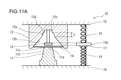
[FIG. 11A] FIG. 11A is a diagram showing the status of a first press working
step by
the first producing apparatus in the first embodiment, and showing the state
before
starting the forming.
[FIG. 11B] FIG. 11B is a diagram showing the status of the first press working
step
by the first producing apparatus in the first embodiment, and showing the
state of the
early phase of the forming.
[FIG. 11C] FIG. 11C is a diagram showing the status of the first press working
step
by the first producing apparatus in the first embodiment, and showing the
state of the
end phase of the forming.
[FIG. 11D] FIG. 11D is a diagram showing the status of the first press working
step
by the first producing apparatus in the first embodiment, and showing the
state at the
completion of the forming.
[FIG. 12A] FIG. 12A is a diagram showing the status of a second press working
step
by the second producing apparatus in the first embodiment, and showing the
state
before starting the forming.
[FIG. 12B] FIG. 12B is a diagram showing the status of the second press
working
step by the second producing apparatus in the first embodiment, and showing
the
state of the end phase of the forming.
[FIG. 12C] FIG. 12C is a diagram showing the status of the second press
working
step by the second producing apparatus in the first embodiment, and showing
the
state at the completion of the forming.
DESCRIPTION OF EMBODIMENTS
[0043]
As a result of a great deal of considerations for solving the above-described
objects, the inventors have obtained the findings (A) and (B).
[0044]
(A) When forming, by the pad bending forming, a press formed product
having a channel cross-section or a hat-shaped cross-section including a shape-
changing part in a part of a ridge line part, a portion of a material metal
sheet, which
portion is formed into a top panel part, is restrained by a punch and a pad
from
beginning to end. On this occasion, both bending stress and tensile stress are
CA 02961188 2017-03-13
- 17 -
applied to the shape-changing part. Therefore, the region of the shape-
changing
part and the region in the vicinity thereof are tensile-bending-deformed.
Consequently, an excessive deformation/strain tends to occur in the region of
the
shape-changing part and the region in the vicinity thereof. This excessive
deformation/strain causes cracks.
[0045]
Accordingly, it can be said that the occurrence of cracks can be reduced by
suppressing the excessive deformation/strain by alleviating tensile bending
deformation in the shape-changing part. In order to do so, the restraining of
the
material metal sheet by the punch and the pad may be alleviated during the
forming.
[0046]
(B) When forming a press formed product having a hat-shaped cross-section
by the pad bending forming, the forming of the top panel part, the vertical
wall parts
and the flange parts is simultaneously completed. In this case, due to
springback,
the vertical wall parts tend to warp outwardly. In order to reduce this
warping of
the vertical wall parts, the forming of the flange parts may be performed
lastly.
[0047]
The present invention has been completed on the basis of the above-described
findings. Hereinafter, a description will be given of embodiments of the
present
invention with reference to the drawings.
[0048]
[First Embodiment]
FIG. 9 is a perspective view showing an example of the structure of a first
producing apparatus used in producing a press formed product in a first
embodiment
of the present invention. FIG. 10 is a perspective view showing an example of
the
structure of a second producing apparatus used in producing the press formed
product in the first embodiment of the present invention. In the first
embodiment,
the case is illustrated where the first exemplary press formed product 7,
having the
hat-shaped cross-section shown in the above-described FIG. 2, is produced. In
the
first embodiment, the press formed product is produced sequentially through a
first
press working step and a second press working step. In the first press working
step,
a first press forming apparatus 10 (the first producing apparatus) shown in
FIG. 9 is
CA 02961188 2017-03-13
- 18 -
used. In the second press working step, a second press forming apparatus 20
(the
second producing apparatus) shown in FIG. 10 is used. That is, the first press
forming apparatus 10 and the second press forming apparatus 20 constitute a
series
of producing equipment lines.
[0049]
FIGS. 11A to 11D are diagrams showing the statuses of the first press
working step by the first producing apparatus in the first embodiment. In
these
figures, FIG. 11A shows the state before starting the forming. FIG. 11B shows
the
state of the early phase of the forming. FIG. 11C shows the state of the end
phase
of the forming. FIG. 11D shows the state at the completion of the forming.
FIGS.
12A to 12C are diagrams showing the statuses of the second press working step
by
the second producing apparatus in the first embodiment. In these figures, FIG.
12A
shows the state before starting the forming. FIG. 12B shows the state of the
end
phase of the forming. FIG. 12C shows the state at the completion of the
forming.
These figures show the cross sections of the region of the shape-changing
part.
[0050]
[First Producing Apparatus]
As shown in FIG. 9 and FIGS. 11A to 11D, the first press forming apparatus
includes a first punch 11 as a lower die, and includes a first die 12 and a
first pad
13 as an upper die. That is, the first punch 11 makes a pair with the first
die 12 and
the first pad 13. Note that FIG. 9 shows the first die 12 by a dashed line, so
as to
facilitate the understanding of the structure.
[0051]
The first punch 11 includes a top surface 11 a (a front end surface), a pair
of
side surfaces 11b, and punch shoulder parts 11c provided between the top
surface
Ila and the side surfaces 11b. The punch shoulder parts 11c are regions
connecting
the top surface 11 a to the side surfaces 11b. The shape of the top surface 11
a is the
shape corresponding to the top panel part of the press formed product. The
shapes
of the side surfaces llb are the shapes corresponding to the vertical wall
parts of the
press formed product. The shapes of the punch shoulder parts 11c are the
shapes
corresponding to the ridge line parts of the press formed product. A shape-
changing part, which changes the shape, is formed in a part of the extending
CA 02961188 2017-03-13
- 19 -
direction of the punch shoulder part 11c. The shape of the shape-changing part
of
this punch shoulder part 11c is the shape corresponding to the shape-changing
part
that exists in a part of the ridge line part of the press formed product. That
is, the
punch shoulder part 11c changes the cross-section shape in its extending
direction, or
includes a part where the extending direction is curved.
[0052]
The first pad 13 is arranged opposed to the top surface lla of the first punch
11. The first die 12 includes a concave part 12c at the position opposed to
the top
surface 11 a of the first punch 11. The first pad 13 can be received in this
concave
part 12c. The first pad 13 constitutes a part of the first die 12 with being
received in
the concave part 12c of the first die 12. Further, the first die 12 includes
corner
parts 12d at the positions opposed to the punch shoulder parts llc of the
first punch
11. The shapes of these corner parts 12d are the shapes conforming to the
punch
shoulder parts tic. Further, the first die 12 includes a pair of first inner
side
surfaces 12a adjacent to the corner parts 12d. The first inner side surfaces
12a are
opposed to the side surfaces llb of the first punch 11. The shapes of the
first inner
side surfaces 12a are the shapes corresponding to predetermined regions of the
regions of the vertical wall parts of the press formed product, the
predetermined
regions having a predetermined height h from the top panel part. Further, the
first
die 12 includes a pair of second inner side surfaces 12b adjacent to the first
inner side
surfaces 12a. The interval between the opposing second inner side surfaces 12b
is
largely expanded outwardly in the width direction of the first die 12.
[0053]
As shown in FIGS. 11A to 11D, the first pad 13 is supported by a die holder
15, which holds the first die 12, via a first pressure member 16. The first
pressure
member 16 is a hydraulic cylinder, a gas cylinder, a spring, a rubber, etc.,
and applies
a downward force (a force directed to the first punch 11) to the first pad 13.
In
FIGS. 11A to 11D, an arm part 13a protrudes from the first pad 13, and the
first
pressure member 16 is provided between this arm part 13a and the die holder
15.
As long as the first pad 13 is supported via the first pressure member 16, the
first pad
13 may be supported by a slide that operates integrally with the first die 12
or the die
holder 15.
CA 02961188 2017-03-13
- 20 -
[0054]
Here, the first press forming apparatus 10 includes a pad adjusting mechanism
that adjusts the distance from the top surface ha of the first punch 11 to the
first pad
13. The pad adjusting mechanism is constituted as follows, for example. As
shown in FIGS. 11A to 11D, a block 17 is provided directly beneath the arm
part 13a
protruding from the first pad 13. This block 17 is supported by a punch holder
18,
which holds the first punch 11, via a second pressure member 19. The second
pressure member 19 is a hydraulic cylinder, a gas cylinder, a spring, a
rubber, etc.,
and applies an upward force (a force directed to the first die 12) to the
block 17.
The upward force applied to the block 17 by the second pressure member 19 is
greater than the downward force applied to the first pad 13 by the first
pressure
member 16. As long as the block 17 is supported via the second pressure member
19, the block 17 may be supported on a base of a pressing machine.
[0055]
With the pad adjusting mechanism, as shown in FIG. 11A, the first pad 13
descends following the descending of the first die 12, and when the distance
of the
first pad 13 from the top surface 11 a of the first punch 11 reaches a
predetermined
distance, the arm part 13a contacts the block 17. Thereafter, as shown in FIG.
11B,
even if the descending of the first die 12 is further continued, the first pad
13 is held
in the position until the first pad 13 is received in the concave part 12c of
the first die
12. This is because the first pad 13 is subjected to the upward force from the
second pressure member 19 greater than the downward force from the first
pressure
member 16. Then, as shown in FIGS. 11C and 11D, when the first pad 13 is
received in the concave part 12c of the first die 12, thereafter, the first
pad 13
descends integrally with the first die 12.
[0056]
[Second Producing Apparatus]
As shown in FIG. 10 and FIGS. 12A to 12C, the second press forming
apparatus 20 includes a main second punch 21 and a sub second punch 24 as a
lower
die, and includes a second die 22 and a second pad 23 as an upper die. That
is, the
main second punch 21 and the sub second punch 24 make a pair with the second
die
CA 02961188 2017-03-13
-21-
22 and the second pad 23. Note that FIG. 10 shows the second die 22 by a
dashed
line, so as to facilitate the understanding of the structure.
[0057]
The main second punch 21 includes a top surface 21a (a front end surface), a
pair of side surfaces 21b, and punch shoulder parts 21c provided between the
top
surface 21a and the side surfaces 21b. The punch shoulder parts 21c are
regions
connecting the top surface 21a to the side surfaces 21b. The shape of the top
surface 21a is the shape corresponding to the top panel part of the press
formed
product. The shapes of the side surfaces 21b are the shapes corresponding to
the
vertical wall parts of the press formed product. The shapes of the punch
shoulder
parts 21c are the shapes corresponding to the ridge line parts of the press
formed
product. A shape-changing part, which changes the shape, is formed in a part
of the
extending direction of the punch shoulder part 21c. The shape of the shape-
changing part of this punch shoulder part 21c is the shape corresponding to
the
shape-changing part that exists in a part of the ridge line part of the press
formed
product. Further, the main second punch 21 includes curved surfaces 21d
adjacent
to its side surfaces 21b.
[0058]
The sub second punch 24 is arranged outside of the main second punch 21
and adjacent to the main second punch 21. The sub second punch 24 includes top
surfaces 24a (front end surfaces). The shapes of the top surfaces 24a are the
shapes
corresponding to the flange parts of the press formed product.
[0059]
The second pad 23 is arranged opposed to the top surface 21a of the main
second punch 21. The second die 22 includes a concave part 22c at the position
opposed to the top surface 21a of the main second punch 21. The second pad 23
can be received in the concave part 22c. The second pad 23 constitutes a part
of the
second die 22 with being received in the concave part 22c of the second die
22.
Further, the second die 22 includes corner parts 22d at the positions opposed
to the
punch shoulder parts 21c of the main second punch 21. The shapes of the corner
parts 22d are the shapes conforming to the shapes of the punch shoulder parts
21c.
Further, the second die 22 includes a pair of inner side surfaces 22a adjacent
to the
CA 02961188 2017-03-13
- 22 -
corner parts 22d. The inner side surfaces 22a are opposed to the side surfaces
21b
of the main second punch 21. The shapes of the inner side surfaces 22a are the
shapes corresponding to the vertical wall parts of the press formed product.
Further,
the second die 22 includes a pair of die shoulder parts 22e adjacent to the
inner side
surfaces 22a. The shapes of the die shoulder parts 22e are the shapes
corresponding
to the ridge line parts that exist between the vertical wall parts and the
flange parts of
the press formed product. Further, the second die 22 includes a pair of bottom
surfaces 22e (front end surfaces) adjacent to the die shoulder parts 22e. The
bottom
surfaces 22e are opposed to the sub second punch 24.
[0060]
As shown in FIGS. 12A to 12C, the second pad 23 is supported by a die
holder 27, which holds the second die 22, via a third pressure member
(illustration
omitted). The third pressure member is a hydraulic cylinder, a gas cylinder, a
spring, a rubber, etc., and applies a downward force (a force directed to the
main
second punch 21) to the second pad 23. As long as the second pad 23 is
supported
via the third pressure member, the second pad 23 may be supported by a slide
that
operates integrally with the second die 22 or the die holder 27.
[0061]
Here, the second press forming apparatus 20 includes a sub punch adjusting
mechanism that delays the pushing-in of the sub second punch 24 with respect
to the
second die 22 later than the pushing-in of the main second punch 21 with
respect to
the second die 22. The sub punch adjusting mechanism is configured, for
example,
as follows. As shown in FIG. 12A to 12C, the sub second punch 24 is held by a
punch holder 28. The main second punch 21 protrudes from the sub second punch
24, and is supported by the punch holder 28 via a fourth pressure member 26.
The
fourth pressure member 26 is a hydraulic cylinder, a gas cylinder, a spring, a
rubber,
etc., and applies an upward force (a force directed to the second die 22) to
the main
second punch 21. The upward force applied to the main second punch 21 by the
fourth pressure member 26 is greater than the downward force applied to the
second
pad 23 by the third pressure member. As long as the main second punch 21 is
supported via the fourth pressure member 26, the main second punch 21 may be
supported on a base of a pressing machine.
CA 02961188 2017-03-13
- 23 -
[0062]
With the sub punch adjusting mechanism, as shown in FIGS. 12A and 12B,
the second pad 23 is received in the concave part 22c of the second die 22
following
the descending of the second die 22. In this manner, the pushing-in of the
main
second punch 21 with respect to the second die 22 is completed. Then, when the
descending of the second die 22 is continued, thereafter, the main second
punch 21
descends integrally with the second die 22 and the second pad 23. In this
manner,
the pushing-in of the sub second punch 24 with respect to the second die 22 is
performed.
[0063]
[Producing of Press Formed Product]
A producing method of the press formed product 7 using the above-described
first press forming apparatus 10 (the first producing apparatus) and the
second press
forming apparatus 20 (the second producing apparatus) includes each of the
following steps.
[0064]
[Preparation Step]
As shown in FIG. 9 and FIG. 11A, a metal sheet 14 is prepared as a starting
material. For example, a high-strength steel sheet having a tensile strength
of 590
MPa or more can be used as the metal sheet 14. The metal sheet 14 may be a 980
MPa-class high-strength steel sheet, or a 1180 MPa-class high-strength steel
sheet.
Additionally, a stainless steel sheet, an aluminum sheet, a copper sheet, etc.
may also
be used as the metal sheet 14.
[0065]
[First Press Working Step]
As shown in FIG. 9 and FIGS. 11A to 11D, in the first press working step,
press working by bending forming is performed on the metal sheet 14 by using
the
first press forming apparatus 10, so as to produce an intermediate formed
product 25.
The intermediate formed product 25 includes a top panel part 25a, ridge line
parts
25b, and vertical wall parts 25c. The top panel part 25a corresponds to the
top
panel part 7a of the press formed product 7. The ridge line parts 25b
correspond to
the ridge line parts 7b of the press formed product 7. The region of the
vertical wall
CA 02961188 2017-03-13
- 24 -
part 25c is segmented into a predetermined region 25ca leading to the ridge
line part
25b, and an excessive region 25cb leading to a first vertical wall part 25c.
The
predetermined region 25ca corresponds to the region having a predetermined
height
h from the top panel part 7a of the region of the vertical wall part 7c of the
press
formed product 7. The excessive region 25cb is the region over the
predetermined
height h. That is, the excessive region 25cb is the region formed in the
vertical wall
part 7c of the press formed product 7 except for the predetermined region
25ca.
Note that the region formed into the flange part 7d of the press formed
product 7 is
also included in the excessive region 25cb. Hereinafter, a specific
description will
be given of the statuses in the first press working step.
[0066]
After placing the metal sheet 14 on the first punch 11, the first die 12 is
descended. On this occasion, the arm part 13a is separated from the block 17,
and
the first pad 13 descends integrally with the first die 12. Then, as shown in
FIG.
11A, the arm part 13a contacts the block 17. At this moment, the distance of
the
first pad 13 from the top surface 11 a of the first punch 11 reaches a
predetermined
distance. Additionally, the second inner side surfaces 12b of the first die 12
contact
both edges of the metal sheet 14. The descending of the first pad 13 is
limited by
the contact between the arm part 13a and the block 17.
[0067]
The descending of the first die 12 is further continued. In this manner, the
pushing-in of the metal sheet 14 into the first die 12 by the first punch 11
is started,
and the bending forming of the metal sheet 14 is begun. On this occasion, as
shown
in FIG. 11B, because the descending of the first pad 13 is limited, the first
pad 13 is
held at the position distant from the top surface lla of the first punch 11 by
the
predetermined distance. Therefore, the metal sheet 14 is gradually deformed to
contact the first pad 13. However, the metal sheet 14 is not sandwiched
between
the first pad 13 and the first punch 11. That is, the metal sheet 14 is not
restrained
by the first pad 13 and the first punch 11.
[0068]
When the descending of the first die 12 is further continued, as shown in FIG.
11C, the pushing-in of the first punch 11 with respect to the first die 12
reaches a
CA 02961188 2017-03-13
- 25 -
predetermined distance short of the bottom dead point for the pushing-in. At
this
moment, the first pad 13 is received in the concave part 12c of the first die
12, and is
integrated with the first die 12. That is, during the time period from when
the
pushing-in of the metal sheet 14 into the first die 12 by the first punch 11
is started or
immediately thereafter until the pushing-in of the first punch 11 with respect
to the
first die 12 reaches the predetermined distance short of the bottom dead point
for the
pushing-in, the first pad 13 is held at the position distant from the top
surface lla of
the first punch 11 by the predetermined distance.
[0069]
Then, the first die 12 and the first pad 13 are descended, and the pushing-in
of
the first punch 11 with respect to the first die 12 and the first pad 13 is
continued to
the bottom dead point. In this manner, the top panel part 25a and the ridge
line
parts 25b are formed. Concurrently with this, the predetermined regions 25ca
of the
vertical wall parts 25c are formed. In this way, the intermediate formed
product 25
is obtained. The top panel part 25a and the ridge line parts 25b of the
intermediate
formed product 25 match the shapes of the top panel part 7a and the ridge line
parts
7b of the press formed product 7 (a part of the ridge line parts 7b includes
the shape-
changing part).
[0070]
With the first press working step using the first press forming apparatus 10
as
described above, the metal sheet 14 is not restrained by the first pad 13 and
the first
punch 11 to the bottom dead point for the pushing-in by the first punch 11
with
respect to the first die 12 and the first pad 13. Therefore, during the
forming, the
restraining of the metal sheet by the punch and the die is alleviated. This
also
alleviates the tensile bending deformation in the shape-changing part and the
excessive deformation/strain is suppressed. As a result, even in the case
where a
high-strength steel sheet is used as a starting material, it is possible to
reduce the
occurrence of cracks in the region of the shape-changing part.
[0071]
As described above, during the forming by the first press working step, the
first pad 13 is temporarily held at the position distant from the top surface
11 a of the
first punch 11 by the predetermined distance. The predetermined distance is
CA 02961188 2017-03-13
- 26 -
preferably 3 mm to 30 mm. The reason is as follows. When the predetermined
distance is less than 3 mm, there is a possibility that the material metal
sheet is
restrained. On the other hand, when the predetermined distance is more than 30
mm, the metal sheet 14 does not contact the first pad 13 during the forming,
and the
first pad 13 loses the reason for its existence.
[0072]
Additionally, in the forming by the first press working step, the
predetermined
regions 25ca, having the predetermined height h from the top panel part 7a, of
the
region of the vertical wall parts 7c of the press formed product 7 are formed.
The
predetermined height h (mm) preferably satisfies the condition of a Formula
(1) as
follows.
Rp h H-Rp ...(1)
Where, in the above Formula (1), H represents the height (mm) of a press
formed product, and Rp represents the radius of curvature (mm) in the cross
section
of the ridge line part.
The radius of curvature Rp here is, in a precise sense, the radius of
curvature
of the inner circumference of the inner and outer circumferences of the ridge
line part.
That is, it corresponds to the radius of curvature of the punch shoulder part
of the
first punch.
[0073]
Additionally, the predetermined height h may satisfy the condition of a
Formula (2) as follows.
H/4 <h 3xH/4 ...(2)
[0074]
[Second Press Working Step]
As shown in FIG. 10 and FIGS. 12A to 12C, in the second press working step,
the press working by bending forming is performed on the intermediate formed
product 25 by using the second press forming apparatus 20, so as to produce
the final
press formed product 7. Hereinafter, a specific description will be given of
the
statuses in the second press working step.
[0075]
CA 02961188 2017-03-13
- 27 -
After placing the intermediate formed product 25 on the main second punch
21, the second die 22 is descended. In this manner, the second pad 23 descends
integrally with the second die 22. Then, as shown in FIG. 12A, the second pad
23
contacts the top panel part 25a of the intermediate formed product 25. In this
manner, the intermediate formed product 25 is sandwiched between the second
pad
23 and the main second punch 21. Additionally, the descending of the second
pad
23 is limited in the state where the intermediate formed product 25 is
restrained by
the second pad 23 and the main second punch 21.
[0076]
The descending of the second die 22 is further continued. In this manner,
the pushing-in of the intermediate formed product 25 into the second die 22 by
the
main second punch 21 is started, and the bending forming of the intermediate
formed
product 25 is begun.
[0077]
When the descending of the second die 22 is further continued, as shown in
FIG. 12B, the pushing-in by the main second punch 21 with respect to the
second die
22 reaches the bottom dead point for the pushing-in. On this occasion, the
second
pad 23 is received in the concave part 22c of the second die 22, and is
integrated with
the second die 22. At the same time, the main second punch 21 is integrated
with
the second die 22 and the second pad 23. In this manner, the top panel part 7a
and
the ridge line parts 7b of the press formed product 7 are completely formed.
Further, the regions of the vertical wall parts 7c of the press formed product
7 are
completely formed from the predetermined regions 25ca of the intermediate
formed
product 25, and from the excessive regions 25cb of the intermediate formed
product
25.
[0078]
The descending of the second die 22 and the second pad 23 is further
continued. In this manner, the pushing-in of the intermediate formed product
25
into the second die 22 and the second pad 23 by the sub second punch 24 is
started.
Then, the second die 22 and the second pad 23 are descended, and the pushing-
in of
the sub second punch 24 with respect to the second die 22 and the second pad
23 is
continued to the bottom dead point. In this manner, the flange parts 7d are
formed
CA 02961188 2017-03-13
- 28 -
from the excessive regions 25cb of the intermediate formed product 25. In this
way,
the press formed product 7 is obtained.
[0079]
With the second press working step using the second press forming apparatus
20 as described above, the forming of the flange parts is performed lastly. In
this
manner, it is possible to reduce the warping of the vertical wall parts
generated due
to springback. That is, the shape fixability is improved.
[0080]
Accordingly, even in the case where the press formed product having a
relatively complex shape is produced, it is possible to expedite the
increasing of the
strength, and it is also possible to increase the degree of freedom in
designing.
[0081]
[Press Formed Product]
The first exemplary press formed product 7, having the hat-shaped cross-
section shown in the above-described FIG. 2A, was produced according to the
producing method of the first embodiment. A 590 MPa-class high-strength steel
sheet was used as the starting material. In this press formed product 7, a
crack did
not occur in the regions of the shape-changing parts 9.
[0082]
Additionally, the maximum principle strain in the regions of the shape-
changing parts 9 was studied. In the press formed product 7 according to the
first
embodiment, the maximum principle strain was 0.22. On the other hand, in the
press formed product 7 by the pad bending forming shown in the above-described
FIG. 1, the maximum principle strain was as high as 0.26.
[0083]
Additionally, the amount of warping of the vertical wall parts 7c was studied.
The interval between the lower ends of the pair of vertical wall parts 7c was
evaluated as the amount of warping. The amount of warping in the press formed
product 7 according to the first embodiment was reduced to about 13%, compared
to
the amount of warping in the press formed product by the pad bending forming
shown in the above-described FIG. 1.
[0084]
CA 02961188 2017-03-13
- 29 -
The press formed product to be produced in the first embodiment is not
limited to the first exemplary press formed product 7 having the hat-shaped
cross-
section shown in FIG. 2A. That is, the press formed product may be the second
to
seventh exemplary press formed products 7 shown in the above-described FIGS. 3
to
8, as long as a part of the ridge line part includes a shape-changing part. In
short,
the shape-changing part of the ridge line part of the press formed product is
at least
one of (a) to (f) as follows:
(a) the height of the ridge line part is changed;
(b) the arc length in the cross section of the ridge line part is changed;
(c) the ridge line part is twisted;
(d) the ridge line part is bent in the width direction;
(e) the ridge line part protrudes or is hollowed in the width direction; and
(0 the radius of curvature in the cross section of the ridge line part is
changed.
[0085]
Note that, in the second to seventh exemplary press formed products 7 shown
in the above-described FIGS. 3 to 8, a wrinkle is likely to be generated in
the regions
of the shape-changing parts 9 and in the region in the vicinity thereof
According to
the first embodiment, it is also possible to suppress such a wrinkle.
[0086]
Additionally, the pair of ridge line parts of the press formed product does
not
have to be parallel. For example, a pair of ridge line parts may be crossed at
their
ends.
[0087]
[Second Embodiment]
A second embodiment is based on the first embodiment, and modifies a part
of the first embodiment. When the main objective is to reduce a crack in the
region
of the shape-changing part, the second press working step by the above-
described
second press forming apparatus can be omitted. In this case, as for the first
die 12
shown in FIG. 9 and FIGS. 11A to 11D, the second inner side surfaces 12b are
omitted, and the first inner side surfaces 12a, having the shapes
corresponding to the
vertical wall parts 7c of the press formed product 7, are extended to the
regions of the
second inner side surfaces 12b. In this manner, the final press formed product
is
CA 02961188 2017-03-13
- 30 -
formed in the first press working step by the above-described first press
forming
apparatus. The second embodiment can be applied to the producing of the press
formed product whose height is not so high, and especially, it can be applied
to the
producing of the press formed product having a channel cross-section without
flange
parts.
[0088]
[Third Embodiment]
A third embodiment is based on the first embodiment, and modifies a part of
the first embodiment. When the main objective is to reduce a crack in the
region of
the shape-changing part as in the above-described second embodiment, in the
above-
described second press working step, a simple pad bending forming may be
performed on the intermediate formed product, or the bending forming without a
pad
may be performed on the intermediate formed product.
[0089]
[Fourth Embodiment]
A fourth embodiment is based on the first embodiment, and modifies a part of
the first embodiment. When the main objective is to reduce the warping of the
vertical wall parts, the first press working step by the above-described first
press
forming apparatus can be omitted. In this case, in the second press working
step by
the above-described second press forming apparatus, a metal sheet is used as
the
starting material, and the final press formed product is formed. Additionally,
a
preliminary press working step instead of the first press working step can be
introduced, and the above-described intermediate formed product can be formed
in
this preliminary press working step. In the preliminary press working step, a
simple
pad bending forming may be performed on a:metal sheet.
[0090]
Also, needless to say, the present invention is not limited to the above-
described embodiments, and various modifications can be made without departing
from the spirit of the present invention. For example, though the first press
forming
apparatus of the above-described embodiments has the structure that includes
the
first punch as the lower die, and includes the first die and the first pad as
the upper
die, the first press forming apparatus of the above-described embodiments may
have
CA 02961188 2017-03-13
- 31 -
the structure in which the arrangement of the upper and lower dies is
inverted.
Although the second press forming apparatus of the above-described embodiments
has the structure that includes the main second punch and the sub second punch
as
the lower die, and includes the second die and the second pad as the upper
die, the
second press forming apparatus of the above-described embodiments may have the
structure in which the arrangement of the upper and lower dies is inverted.
[0091]
Additionally, the first pad of the first press forming apparatus is preferably
arranged opposed to the front end surface of the first punch, at least in the
cross
section that is perpendicular to the extending direction of the punch shoulder
part in
the shape-changing part. That is, the first pad is preferably provided at the
position
that at least overlaps the shape-changing part in the ridge line part of the
press
formed product. However, it is not necessary for the first pad to be provided
at the
position that overlaps the shape-changing part in the ridge line part of the
press
formed product. That is, the first pad may be provided at the position that
overlaps
with a vicinity part, if the vicinity part is within 100 mm from the shape-
changing
part in the ridge line part of the press formed product.
REFERENCE SIGNS LIST
[0092]
7: press formed product, 7a: top panel part, 7b: ridge line part, 7c: vertical
wall part,
7d: flange part,
8: step height part, 9: shape-changing part,
10: first press forming apparatus,
11: first punch, 11 a: front end surface, lib: side surface,
lie: punch shoulder part,
13: first pad, 13a: arm part,
12: first die, 12a: first inner side surface, 12b: second inner side surface,
12c: concave part, 12d: corner part,
14: starting material (metal sheet), 15: die holder,
16: first pressure member, 17: block,
18: punch holder, 19: second pressure member,
CA 02961188 2017-03-13
- 32 -
20: second press forming apparatus,
21: main second punch, 21a: front end surface, 21b: side surface,
21c: punch shoulder part, 21d: curved surface,
22: second die, 22a: inner side surface, 22c: concave part,
22d: corner part, 22e: die shoulder part, 22f: front end surface,
23: second pad,
24: sub second punch, 24a: top surface,
25: intermediate formed product,
25a: top panel part, 25b: ridge line part, 25c: vertical wall part,
25ca: predetermined region, 25cb: excessive region
26: fourth pressure member, 27: die holder, 28: punch holder