Note: Descriptions are shown in the official language in which they were submitted.
CA 2961221 2017-03-17
MODULAR GARAGE DOOR OPENER
CROSS-REFERENCE TO RELATED APPLICATIONS
[0001] This application claims priority to co-pending U.S. Provisional
Patent Application
No. 62/321,188 filed on April 11, 2016, the entire content of which is
incorporated herein by
reference.
FIELD OF THE INVENTION
[0002] The present invention relates to garage door openers, and more
particularly to
garage door openers with accessories.
SUMMARY OF THE INVENTION
[0003] The present invention provides, in one aspect, a modular garage
door opener
system including an accessory device having a first electronic processor, a
first memory, and a
load that is controllable by the first electronic processor, a garage door
opener having a motor
configured to drive a garage door to open and close, an accessory port, a
second memory, and a
second electronic processor. The accessory port is configured to be removably
coupled to the
accessory device such that the accessory device is in electrical communication
with the
accessory port. The second electronic processor is coupled to the second
memory and is
configured to execute instructions stored in the second memory to receive new
status data from
the accessory device indicating a change in a status of the accessory device
to a new status, send
the new status data to a remote server to update an accessory data set,
receive new settings data
from the remote server indicating a requested change in a setting of the
accessory device, and
send the new settings data to the accessory device to update the setting of
the accessory device
and, thereby, control the load of the accessory device.
[0004] The present invention provides, in another aspect, a communication
method for a
garage door opener including an accessory port configured to receive an
accessory device. The
method includes the garage door opener receiving the accessory device in the
accessory port.
The method also includes the garage door opener receiving, from the accessory
device, an initial
data set including a unique identifier for the accessory device, an initial
status indicating a status
1
=
CA 2961221 2017-03-17
of the accessory device, and an initial setting indicating a setting of the
accessory device. The
method also includes the garage door sending, by an electronic processor of
the garage door
opener, the initial data set to a remote server for storage as an accessory
data set. The method
also includes the garage door opener receiving, by the electronic processor,
new status data from
the accessory device indicating a change in the status of the accessory device
to a new status.
The method also includes the garage door opener sending, by the electronic
processor, the new
status data to the remote server to update the accessory data set. The method
also includes the
garage door receiving, by the electronic processor, new settings data from the
remote server
indicating a requested change in the setting of the accessory device. The
method also includes
the garage door opener sending, by the electronic processor, the new settings
data to the
accessory device to update the setting of the accessory device.
[0005] The present invention provides, in another aspect, a
communication method for an
accessory device configured to be coupled to an accessory port of a garage
door opener. The
method includes the accessory device receiving power from the accessory port
upon being
coupled to the accessory port. The method also includes the accessory device
sending to the
garage door opener, by an electronic processor of the accessory device, an
initial data set
including a unique identifier for the accessory device, an initial status
indicating a status of the
accessory device, and an initial setting indicating a setting of the accessory
device. The method
also includes the accessory device receiving, by the electronic processor, new
settings data, from
the garage door opener, to update the setting of the accessory device. The
method also includes
controlling, by the electronic processor, a load of the accessory device in
response to the new
settings data. The method also includes sending, by the electronic processor,
new status data, to
the garage door opener, indicating a change in the status of the accessory
device to a new status.
[0006] The present invention also provides, in another aspect, a
communication method
for a remote server configured to communicate with a peripheral device and an
accessory device
coupled to an accessory port of a garage door opener. The method includes the
remote server
receiving from the garage door opener, by an electronic processor of the
remote server, an initial
data set including a unique identifier for the accessory device, an initial
status indicating a status
of the accessory device, and an initial setting indicating a setting of the
accessory device. The
method also includes the remote server storing, by the electronic processor,
the initial data set as
2
=
CA 2961221 2017-03-17
an accessory data set associated with the accessory port of the garage door
opener. The method
also includes the remote server sending, by the electronic processor, the
initial data set to the
peripheral device. The method also includes the remote server receiving, by
the electronic
processor, new status data from the garage door opener. The method also
includes the remote
server sending, by the electronic processor, the new status data to the
peripheral device. The
method also includes the remote server receiving, by the electronic processor,
new settings data
from the peripheral device. The method also includes the remote server
sending, by the
electronic processor, the new settings data to the garage door opener, wherein
a load of the
accessory device is controlled in response to the new settings data.
[0007] In some instances, the method may also include the remote server
updating, by
the electronic processor, the accessory data set to include the new status
data, and updating, by
the electronic processor, the accessory data set to include the new settings
data.
[0008] In some instances, the method may also include the remote server
receiving from
the garage door opener, by the electronic processor, an second initial data
set including a second
unique identifier for a second accessory device, a second initial status
indicating a second status
of the second accessory device, and a second initial setting indicating a
second setting of the
second accessory device. The method may also include the remote server
storing, by the
electronic processor, the second initial data set as a second accessory data
set associated with a
second accessory port of the garage door opener. The method may also include
the remote
server sending, by the electronic processor, the second initial data set to
the peripheral device.
The method may also include the remote server receiving, by the electronic
processor, second
new status data from the garage door opener. The method may also include the
remote server
sending, by the electronic processor, the second new status data to the
peripheral device. The
method may also include the remote server receiving, by the electronic
processor, second new
settings data from the peripheral device. The method may also include the
remote server
sending, by the electronic processor, the second new settings data to the
garage door opener,
wherein a second load of the second accessory device is controlled in response
to the second new
settings data.
3
CA 2961221 2017-03-17
[0009] In some instances, after the second accessory device is
disconnected from the
second accessory port and the accessory device is disconnected from the
accessory port, and
after the second accessory device is connected to the accessory port,
receiving, by the electronic
processor, the second initial data set from the garage door opener, the method
may include the
remote server storing, by the electronic processor, the second initial data
set as the accessory data
set associated with the accessory port of the garage door opener. The method
may also include
sending, by the electronic processor, the second initial data set to the
peripheral device.
[00101 The invention also provides, in another aspect, a communication
method for a
peripheral device configured to communicate with an accessory device coupled
to an accessory
port of a garage door opener, the method comprising. The method includes the
peripheral device
receiving from a remote server, by an electronic processor of the peripheral
device, an initial data
set including a unique identifier for the accessory device, an initial status
indicating a status of
the accessory device, and an initial setting indicating a setting of the
accessory device. The
method includes the peripheral device receiving, by the electronic processor,
new status data for
the accessory device from the remote server indicating a change in the status
of the accessory
device to a new status. The method includes the peripheral device receiving,
by the electronic
processor, user input indicating a requested change of the setting of the
accessory device. The
method includes the peripheral device sending, by the electronic processor,
new settings data
indicating the requested change to the remote server to control a load of the
accessory device.
100111 In some instances, the method may also include the peripheral
device displaying,
on a display of the peripheral device, the accessory device based on the
unique identifier and the
status of the accessory device based on the initial status. The method may
also include the
peripheral device displaying, on the display of the peripheral device, the new
status of the
accessory device upon receipt of the new status data.
100121 In some instances, the method may also include the peripheral
device receiving
from the remote server, by the electronic processor, a second initial data set
including a second
unique identifier for a second accessory device, a second initial status
indicating a second status
of the second accessory device, and a second initial setting indicating a
second setting of the
second accessory device. The method may also include the peripheral device
receiving, by the
4
CA 2961221 2017-03-17
electronic processor, second new status data for the second accessory device
from the remote
server indicating a change in the second status of the second accessory device
to a second new
status. The method may also include the peripheral device receiving, by the
electronic processor,
second user input indicating a second requested change of the second setting
of the second
accessory device. The method may also include the peripheral device sending,
by the electronic
processor, second new settings data indicating the second requested change to
the remote server
to control a second load of the second accessory device.
[0013] In some instances, the method may also include the peripheral
device receiving
from the remote server, by the electronic processor, a second initial data set
including a second
unique identifier for a second accessory device, a second initial status
indicating a second status
of the second accessory device, and a second initial setting indicating a
second setting of the
second accessory device. The method may also include the peripheral device
displaying, on a
display of the peripheral device, the accessory device based on the unique
identifier and the
status of the accessory device based on the initial status. The method may
also include the
peripheral device displaying, on the display of the peripheral device, the
second accessory device
based on the second unique identifier and the second status of the accessory
device based on the
second initial status.
[0014] Other features and aspects of the invention will become apparent
by consideration
of the following detailed description and accompanying drawings.
BRIEF DESCRIPTION OF THE DRAWINGS
[0015] FIG. 1 is a perspective view of a garage door opener system.
[0016] FIG. 2 is a first perspective view of a garage door opener.
[0017] FIG. 3 is a housing of the garage door opener of FIG. 2.
[0018] FIG. 4 is a side view of the housing of FIG. 3.
[0019] FIG. 5 is a schematic of the garage door opener.
[0020] FIG. 6 is a second schematic of the garage door opener.
=
CA 2961221 2017-03-17
[0021] FIG. 7 is a schematic of communication boards within the
garage door opener.
[0022] FIG. 8 is a second perspective view of the garage door
opener.
[0023] FIG. 9A is a third perspective view of the garage door
opener.
[0024] FIG. 9B is a fourth perspective view of the garage door
opener.
[0025] FIG. 10 is a block diagram of a battery pack.
[0026] FIG. 11 is a front perspective view of an accessory
speaker.
[0027] FIG. 12 is a rear perspective view of the accessory
speaker.
[00281 FIG. 13 is a front perspective view of an accessory fan.
[0029] FIG. 14 is a rear perspective view of the accessory fan.
[0030] FIG. 15 is a front perspective view of an accessory cord
reel.
[0031] FIG. 16 is a rear perspective view of the accessory cord
reel.
[0032] FIG. 17 is a front perspective view of an accessory
environmental sensor.
[0033] FIG. 18 is a front perspective view of an accessory park-
assist laser.
[0034] FIG. 19 is a perspective view of the garage door opener
system including the
accessory park-assist laser of FIG. 18.
[0035] FIG. 20 is a perspective view of an accessory folding
light.
[0036] FIG. 21 is a perspective view of an accessory area light.
[0037] FIG. 22 is a perspective view of an accessory inflator.
[0038] FIG. 23 is a perspective view of a pair of obstruction
sensors.
[0039] FIG. 24 is a perspective view of the obstruction sensors
of FIG. 23 being used in
the garage door opener system.
6
CA 2961221 2017-03-17
[0040] FIG. 25 is a perspective view of an outdoor keypad for use with
the garage door
opener system of FIG. 1.
[0041] FIG. 26 is a front view of an indoor keypad for use with the
garage door opener
system of FIG. 1.
[0042] FIG. 27 is a perspective view of the garage door opener including
a transceiver in
communication with a peripheral device.
[0043] FIG. 28 is a side view of a removable antenna.
[0044] FIG. 29 is a perspective view of a peripheral device application
for use with the
garage door opener system of FIG. 1.
[0045] FIG. 30 illustrates a module communication method data transfer
structure.
[0046] FIG. 31 is a flow chart illustrating a module communication
method.
[0047] FIG. 32 is a flow chart illustrating a module communication method
according to
another embodiment of the invention.
[0048] FIG. 33 illustrates a block diagram of a remote server of the data
transfer structure
of FIG. 30.
[0049] FIG. 34 illustrates a block diagram of a peripheral device of the
data transfer
structure of FIG. 30.
[0050] FIG. 35 illustrates a block diagram of an accessory device of the
data transfer
structure of FIG. 30.
[0051] FIG. 36 is a schematic of a garage door opener according to a
second embodiment
of the invention.
7
=
CA 2961221 2017-03-17
DETAILED DESCRIPTION
[0052] Before any embodiments of the invention are explained in
detail, it is to be
understood that the invention is not limited in its application to the details
of construction and the
arrangement of components set forth in the following description or
illustrated in the following
drawings. The invention is capable of other embodiments and of being practiced
or of being
carried out in various ways. Also, it is to be understood that the phraseology
and terminology
used herein is for the purpose of description and should not be regarded as
limiting.
[0053] FIGS. 1-36 illustrate a modular garage door system 50
including a garage door
opener 100 operatively coupled to a garage door 104. The garage door opener
100 is configured
to receive a variety of accessory devices 200, such as a battery charger
204/battery pack 208, a
speaker 212, a fan 216, an extension cord reel 220, an environmental sensor
224, a park-assist
laser 228, a folding light 232, a retractable area light 236, and an inflator
cord reel 240. The
garage door system 50 may be operated by a wall-mounted keypad 244, a passcode
keypad 248,
and/or a peripheral device 252 (e.g., a smartphone based application, etc.).
In the illustrated
embodiment, the garage door opener 100 is configured to be coupled directly to
an AC power
source, and optionally use the battery 208 as back-up power source when AC
power is
unavailable. In addition, the accessory devices 200 communicate with the
peripheral device 252
wirelessly via a communication method 900.
[0054] With reference to FIGS. 1-5, the garage door opener 100
includes a housing 108
supporting a motor 112 (e.g., a 2 HP electric motor) that is operatively
coupled to a drive
mechanism 116. The drive mechanism 116 includes transmission coupling the
motor to a drive
chain 120 having a shuttle 124 configured to be displaced along a rail
assembly 128 upon
actuation of the motor 112. The shuttle 124 may be selectively coupled to a
trolley 132 that is
slidable along the rail assembly 124 and coupled to the door 104 via an arm
member.
[0055] With continued reference to FIGS. 1-5, the trolley 132 is
releaseably coupled to
the shuttle 124 such that the garage door system 50 is operable in a powered
mode and a manual
mode. In the powered mode, the trolley 132 is coupled to the shuttle 124 and
the motor 112 is
selectively driven in response to actuation by a user. As the motor 112 is
driven, the drive chain
8
CA 2961221 2017-03-17
120 is driven by the motor 112 along the rail assembly 128 to displace the
shuttle 124 (and
therefore the trolley 132) thereby opening or closing the garage door 104. In
the manual mode,
the trolley 132 is decoupled from the shuttle 124 such that a user may
manually operate the
garage door 104 to open or close without resistance from the motor 112. The
trolley 132 may be
decoupled, for example, when a user applies a force to a release cord 136 to
disengage the trolley
132 from the shuttle 124.
[0056] In another embodiment, the drive mechanism 116 includes a
transmission
coupling the motor 112 to a drive belt that is operatively coupled to the
garage door 104 via a rail
and carriage assembly. The rail and carriage assembly includes a rail that is
coupled to the main
housing and a surface above the garage door opener 100 (e.g., a garage
ceiling) and supports a
trolley coupled to the drive belt. The trolley includes an inner trolley
member and an outer
trolley member. The inner trolley member is coupled to and driven by the belt,
and the outer
trolley member is coupled to the garage door (e.g., via a bracket).
[0057] The inner trolley member and the outer trolley member are
releasably coupled to
one another such that the garage door system 50 is operable in a powered mode
and a manual
mode. In the powered mode, the inner trolley is coupled to the outer trolley
and the motor 112 is
selectively driven in response to actuation by a user. As the motor 112 is
driven, the belt is
driven by the motor 112 along the rail to displace the trolley thereby opening
or closing the
garage door 104. In the manual mode, the outer trolley is decoupled from the
inner trolley such
that a user may manually operate the garage door 104 to open or close without
resistance from
the motor 112.
[0058] FIGS. 2-4 illustrate the garage door opener 100, which includes
the housing 108
supporting the motor 112 (shown in FIG. 5). The housing is encased by an upper
cover 140 and
a lower cover 144 (FIG. 2). The upper cover 140 is coupled to the rail
assembly 128 and the
surface above the garage door (e.g., the garage ceiling) by, for example, a
support bracket 148.
In the illustrated embodiment, the lower cover 144 supports a light 152 (e.g.,
one or more LED
lights), enclosed by a transparent cover or lens 156 (FIG. 8), which provides
light to the garage.
As illustrated in FIG. 2, in which the cover 156 is removed, the light 152
includes a pair of linear
LED strips having a plurality of LEDs disposed at regular intervals along the
LED strips.
9
CA 2961221 2017-03-17
However, in other embodiments, the light 152 may include a single LED strip or
more than two
LED strips. In addition, the strips may have any shape (e.g., arcuate strips
or sections of the
strips, obliquely angled portions, etc.), and may include different patterns
of LED placement.
Furthermore, the LEDs may be configured such that they can emit varying
intensities of light or
colors of light (e.g., via pulse width modulation).
[0059] The light 152 may either be selectively actuated by a user or
automatically
powered upon actuation of the garage door opener 100. In one example, the
light 152 may be
configured to remain powered for a predetermined amount of time after
actuation of the garage
door opener 100, or in response to a signal sent to an accessory device 200 by
a peripheral
device.
[0060] With reference to FIGS. 3 and 4, the housing 108 includes
accessory ports 162
that receive and support modular, interchangeable accessory devices 200. In
the illustrated
embodiment, the housing 108 has eight accessory ports 162 with two ports 162
disposed on each
side of the housing 108. However, this configuration is merely exemplary ¨
that is, the housing
108 may include more than eight ports 162 or less than eight ports 162, and
each side of the
housing 108 may include more or less than two ports 162. Additionally, the
housing 108 may
include more or less than four sides with each having one or more ports 162,
and other surfaces
of the housing (e.g., the top and bottom) may include one or more ports 162.
[0061] With continued reference to FIGS. 3 and 4, each port 162 includes
a
communication interface 166 and a coupling interface 170. The communication
interface 166
includes an electrical connector 174 disposed within a recess 178. The
electrical connector 174
is configured to facilitate electrical communication and data communication
between the
accessory device 200 and the garage door opener 100. The electrical connector
174 may be any
type of powered input/output port. Additionally, in further embodiments the
electrical connector
174 may define separate power connectors and data connectors, which may
similarly be any type
of power connectors and data connectors. In the illustrated embodiment, two
slots 182 are
formed on either side of the electrical connector 174 and receive a portion of
an accessory device
200 to align and mechanically couple the accessory device 200 with housing
108. The coupling
interface 170 is defined by a pair of spaced apart, raised surfaces 186
defined on either side of
=
CA 2961221 2017-03-17
the communication interface 166. Each raised surface 186 includes a chamfered
edge and has an
aperture 190 defined there through. However, the raised surfaces 186 may be
omitted in other
embodiments. The apertures 190 are configured to receive portions of the
accessory devices 200
to facilitate mechanical coupling of the accessory device 200 to the garage
door opener 100.
[0062] In the illustrated embodiment, the housing 108 includes an
electrical outlet 194
(also referred to as a pass-through outlet) disposed between ports 162 on one
or more sides of the
housing 108 (FIG. 3). The electrical outlet 194 is a standard U.S. three-prong
female AC plug
194 defined within a recess 198. However, the electrical outlet 194 may be any
type of AC or
DC electrical outlet. Therefore, an electrical device (e.g., a power tool, an
air compressor, a
light, etc.) including a corresponding connector configured to be coupled to
the electrical outlet
194 may receive AC power from the electrical outlet 194.
[0063] Furthermore, in the illustrated embodiment, one of the ports
162 is omitted such
that a portion of the housing includes a customized port 164 for permanently
receiving a specific
accessory device 200 (e.g., a battery charging port for fixedly receiving a
charger) (FIG. 4). This
type of customized port 164 may also be used in place of other ports 162 in
other embodiments.
[0064] With reference to FIGS. 2 and 5, the garage door opener 100
receives a variety of
different accessory devices 200 within the ports 162. In the illustrated
examples, two ports 162
and the electrical outlet 194 receive the extension cord reel 220 on one side
of the housing 108.
On another side of the housing 108, one port 162 receives the environmental
sensor 224 and the
other port 162 receives the park-assist laser 228. On yet another side, one
port 162 receives the
fan 216 and the other port 162 is unused and blocked by a cover 256. The final
side includes one
of the ports 162 and the customized port 164, where the port 162 receives the
speaker 212 and
the customized port 164 supports the battery charger 204 for receiving a
battery pack 208 (e.g., a
power tool battery pack). Each accessory device 200 will be described in
greater detail below
with reference to FIGS. 11-22.
[0065] With reference to FIGS. 6 and 7, the garage door opener 100
includes a power
inlet 102 configured to receive power from an external power source, such as a
standard 120
VAC power outlet. The power from the external power source is received at a
terminal block
106, which directs power to the motor 112, the light 152, the accessory
devices 200, the
11
CA 2961221 2017-03-17
electrical outlet 194 (via a circuit breaker), and at least one communication
board 160 disposed
on or within the garage door opener 100 via, for example, a DC fuse. The
electrical outlet 194 is
coupled to the AC power source 102 via the terminal block 106 such that the
electrical outlet 194
is a 'pass through outlet receiving standard AC power from the AC power
source. In this
embodiment, the garage door opener 100 includes a garage door opener
communication board
168 having a radio-frequency (RF) receiver 172 and a wireless board 176 having
a transceiver
180. The garage door opener communication board 168 is in communication with
obstruction
sensors 700, the remote controller 253 (also referred to as car remote 253),
the passcode keypad
248, and the wireless board 176 (e.g., via a multiplexer) and is configured to
actuate operation of
the motor 112 based on communications received from the foregoing devices. The
wireless
board 176 is configured to send and receive communications from a network hub
948, a wireless
network 952 (e.g., including a remote server 950 (FIG. 30), a peripheral
device 252, the wall-
mounted keypad 244, and the accessory devices 200. In other embodiments, the
garage door
opener 100 includes a single communication board 168 communicating with each
of the
foregoing devices.
100661 The garage door opener communication board 168 and the wireless
board 176
may be referred to as a controller of the garage door opener, with the
controller including an
electronic processor and memory storing instructions. The electronic processor
executes the
instructions to carry out the functionality of the garage door opener
communication board 168
and the wireless board 176 described herein and, more generally, the control
functionality of the
garage door opener 100 described herein. The controller may reside on the
communications
board 160 of FIG. 6, or may be separated onto separate physical boards. An
example of a
similarly configured controller having an electronic processor and memory,
albeit for a battery
pack, is illustrated in FIG. 10 as controller 1355.
100671 FIGS. 8, 9A, and 9B illustrate the battery charger 204 disposed on
the housing. In
the illustrated embodiment, the battery charger 204 includes a charging port
260 defined by a
recess 138 that is sized and shaped to receive a battery pack 208. The
charging port 260 includes
electrical contacts configured to mechanically and electrically engage a set
of battery pack
contacts to transfer electrical charge from the garage door opener 100 to the
battery pack 208 and
also communicate data signals therebetween. Additionally, the charging port
260 includes a
12
= =
CA 2961221 2017-03-17
mechanical coupling mechanism 264 to engage and retain the battery pack 208
within the
charger 204. The mechanical coupling mechanism 264 includes two slots 142
disposed on
opposed sides of the recess 138 that are configured to receive battery pack
latch members 146 to
secure and maintain engagement of the battery pack 208 and the garage door
opener 100 (FIG.
9A). In the illustrated embodiment, the charging port 260 is configured to
receive a battery pack
208 that is inserted along an insertion axis A. However, in other embodiments,
the battery
receiving portion may be configured to receive a battery pack configured as a
'slide on battery
pack that is inserted along an axis generally perpendicular to the insertion
axis.
[0068] In other embodiments, however, the mechanical coupling
mechanism 264 may be
any other conventional battery pack coupling mechanism, such as those seen in
battery chargers
and/or power tools. The mechanical coupling mechanism may include alignment
rails, pivoting
latch members received in corresponding slots, or other features used to
receive and retain a
battery pack within a charging or power tool port either in place of or in
addition to the features
described above.
[0069] The battery charger 204 further includes a door 268
pivotally coupled to a side of
the battery charger 204 via a hinged connection 272 such that the door 268 is
movable between a
closed position (FIG. 8) and an open position (FIGS. 9A and 9B). The door 268
is configured to
cover the battery charger 204 when a battery pack 208 is not connected.
Additionally, the door
268 is sized and shaped to enclose a battery pack 208 received within the
charger 204. The door
268 is retained in a closed position by a locking mechanism 276 defined by a
press fit detent;
however, other locking mechanisms may be used.
[0070] FIGS. 9A and 9B illustrate battery pack 208 that may be
coupled to the charger
204 via the charging port 260. The battery pack 208 includes latches 146 on
either side of the
pack 208 for engaging the slots 142 of the charging port 260 on the charger
204. The battery
pack 208 further includes an insertion portion 154 that is received by the
charging port 260 of the
charger 204. The insertion portion 154 includes a top support portion having a
stem extending
vertically from the top support portion. The stem has contacts that receive
power from the
charger 204 and may communicate data between the charger 204 and the battery
pack 208. The
battery pack 208 further includes a fuel gauge 1395 that indicates a state of
charge of the battery
13
CA 2961221 2017-03-17
pack. The battery pack 208 may be a power tool battery pack configured to
power tools (e.g.,
drills/drivers, impact drills/drivers, hammer drills/drivers, saws, and
routers) having a battery
receiving portion similar to the charging port 260. In the illustrated
embodiment, when the
battery pack 208 is coupled to the charging port 260 and the door 268 is open,
the fuel gage 1395
is visible to a user (FIG. 9B).
[0071] The battery cells of the battery packs 208 may provide a voltage
output of about
18 volts, of another value in a range between 17 to 21 volts, or another
value, such as about 12
volts, about 28 volts, about 36 volts, about 48 volts, another value or range
between 12 to 48
volts, or another value. The term "about" may indicate a range of plus or
minus 20%, 15%,
10%, 5%, or 1% from an associated value. The battery cells 1350 may have
various chemistry
types, such as lithium ion, a nickel cadmium, etc. In addition, the battery
packs 208 may provide
different capacities in terms of amp-hours because of differences in one or
more of the size,
capacity, and number of cells (e.g., 5 cells, 10, cells 15 cells, etc.).
[0072] When the battery pack 208 is coupled to the battery charger 204,
the battery pack
208 also provides power to the garage door opener 100 when the garage door
opener 100 loses
power ¨ that is, the battery pack 208 serves as a 'DC battery back up. The
garage door opener
100 is configured to detect loss of power and reconfigure the battery charger
204 to receive
power from the battery pack 208 when power is lost. In this way, even when the
garage door
system 50 loses external power, the garage door opener 100 is still able
operate the garage door
104.
[0073] In one embodiment, the garage door opener 100 monitors a voltage
of battery
cells of the battery pack 208 (e.g., at continuous intervals, continuously,
etc.) when the battery
pack 208 is connected to the charger 204 via a charging circuit. The charging
circuit may
include a processor that is configured to monitor battery pack properties
(e.g., type of battery,
charge state, temperature, number of charge cycles, etc.) to determine and
execute a charging
protocol stored in a memory of the charging circuit. The charging protocol may
include a
constant or variable current application, constant or variable voltage
application, a programmed
sequence of constant/variable current and constant/variable voltage, and
automatic shut-off in
response to monitored battery pack properties (e.g., at completed charge, a
temperature
14
CA 2961221 2017-03-17
threshold, etc.). The charging circuit may also be configured to execute a
different charging
protocol for different types of battery packs. For example, the charging
circuit may include a
first charging protocol for a first battery pack (e.g., a lithium ion battery
pack) and a second
charging protocol for a second battery pack (e.g., a nickel cadmium battery
pack).
[0074] In one embodiment, if the charging circuit detects that the
voltage of the battery
pack 208 is below a predetermined level, the charger 204 is configured to
charge the battery 208.
Once the voltage of the battery pack 208 reaches the predetermined level, the
charger 204 is
configured to cease charging operations (e.g., via the use of a relay). In the
case where AC
power is lost, and the battery pack 208 is used as a battery back up to power
the garage door
opener 100, the battery pack 208 is operatively connected to the garage door
opener 100 to
power the motor 112 (e.g., via a relay activated by the loss of AC power). In
other words, and
with reference to FIG. 6, in a power outage, the battery pack 208 provides
power to the circuitry
of the battery charger 204, which forwards the power to reconfigurable backup
relays. The
backup relays include power switching elements that are automatically switched
to accept power
from the battery charger 204 when power is not present from the DC fuse and
that are
automatically switched to accept power from the DC fuse when power (from the
terminal block
106) is present. The DC fuse directs power received, whether from the battery
pack 208 or the
terminal block 106, to the motor 112 and other components of the garage door
opener 100.
100751 In an alternate embodiment, certain control circuitry of the
charging circuit may
be disposed within the battery pack rather than the garage door opener (i.e.,
the battery pack is a
'smart battery pack). In this embodiment, illustrated in FIG. 10, the battery
pack 208 includes
battery cells 1350 and a battery controller 1355 having an electronic
processor 1360 and a
memory 1365. The electronic processor 1360 executes instructions stored in the
memory 1365
to control the functionality of charging circuit described herein, such as to
control the charge and
discharge of the battery cells 1350 (e.g., via switching elements (not
shown)). For example, the
battery controller 1360 may monitor pack properties and execute the charging
functions
described above in response to the monitored pack properties. Additionally,
the battery
controller may either communicate with the charger of the garage door opener
(e.g., via a
connection of a battery data contact and a charger data contact) to control
charging functions
(e.g., operate one or more garage door opener relays) or control functions
within the battery
CA 2961221 2017-03-17
pack. Controlling functions within the battery pack may include, for example,
disconnecting
(e.g., via a relay) the battery pack contacts from battery cells of the
battery pack in response to
any of the monitored battery pack properties described above.
[0076] The charger 204 further includes a controller in communication
with the wireless
board 176 of the garage door opener 100. The controller includes a memory
storing an initial
data set 850 including a unique identifier 854, a predetermined initial status
field 858, and a
predetermined initial settings field 862 that is communicated to the garage
door opener 100 each
time the charger 204 is coupled to the port 162. Thereafter, the controller is
configured to send
and receive data from, for example, the remote server 950 via the wireless
board 176. More
specifically, the controller receives updates to the settings field 862 of the
data set 850 based on
data received from the wireless board 176. The controller also updates the
status field 858 of the
data set 850 (e.g., based on parameters the controller sensors regarding a
coupled battery pack),
which is sent to the wireless board 176 for communication to the peripheral
device via the
remote server 950.
[0077] In one embodiment, the status field 858 includes, for example, the
charge state of
the battery (e.g., full charge or charging, a percentage of charge, etc),
among others. The settings
field 862 includes an on/off toggle for the charging the battery, among
others. In this example,
the user may set the values for the settings field 862 (e.g., via the
peripheral device 252), which
turns the charger on and off, while also monitoring the charge state of the
battery.
[0078] FIGS. 11 and 12 illustrate the accessory speaker 212 configured to
be detachably
coupled to the garage door opener 100. In the illustrated embodiment, the
speaker 212 is a
wireless speaker 212 (e.g., a Bluetootht speaker) that may be wirelessly
coupled to a peripheral
device 252. In one embodiment, the speaker 212 receives an audio stream from a
peripheral
device 252 communicating with the garage door opener 100, and subsequently
drives a speaker
212 to output the audio stream using power from the garage door opener 100 via
the electrical
mounting interface 400. In another embodiment, the wireless speaker 212
receives an audio
stream wirelessly directly from a peripheral device 252 via an integral
transceiver, and drives a
speaker 212 to output the audio stream using power from the garage door opener
100 via the
electrical mounting interface 400.
16
CA 2961221 2017-03-17
[00791 With reference to FIG. 12, the speaker 212 includes a mechanical
mounting
interface 300 configured to be coupled to the coupling interface 170 of the
housing 108, and an
electrical mounting interface 400 configured to be coupled to the
communication interface 166
of the housing 108. The mechanical mounting interface 300 includes a pair of
hooks 304 that are
received within the apertures 190 of the coupling interface 170, a pair of
projections 308
disposed on opposing sides of the electrical mounting interface 400, and at
least one protruding
latch member 312 configured to engage a corresponding retention member on the
housing 108.
The projections 308 are configured to be received within the slots 182 to
assist with alignment of
the electrical mounting interface 400 and the communication interface 166.
When coupled, the
speaker 212 receives power from the garage door opener 100 via connection
defined by between
the electrical mounting interface 400 and the communication interface 166. The
speaker 212
also sends and receives data from the garage door opener 100 via connection
defined by between
the electrical mounting interface 400 and the communication interface 166.
[0080] The speaker 212 further includes a controller in communication
with the wireless
board 176 of the garage door opener 100. The controller includes a memory
storing an initial
data set 850 including a unique identifier 854, a predetermined initial status
field 858, and a
predetermined initial settings field 862 that is communicated to the garage
door opener 100 each
time the speaker 212 is coupled to the port 162. Thereafter, the controller is
configured to send
and receive data from, for example, the remote server 950 via the wireless
board 176. More
specifically, the controller receives updates to the settings field 862 of the
data set 850 based on
data received from the wireless board 176. The controller also updates the
status field 858 of the
data set 850, which is sent to the wireless board 176 for communication to the
peripheral device
via the remote server 950.
[0081] In one embodiment, the status field 858 includes, for example,
on/off state of the
speaker, the pairing status (e.g, Bluetooth0 pairing status), and speaker
volume, among others.
The settings field 862 includes an on/off toggle, a pairing toggle (e.g., to
turn pairing on/off), and
a volume value, among others. In this example, the user may set the values for
the settings field
862 (e.g., via the peripheral device 252), which updates the speaker 212 to
turn on/off, turn
pairing on/off, or alter the volume of the speaker.
17
CA 2961221 2017-03-17
[0082] With reference to FIGS. 13 and 14, the accessory fan 216 includes
a mounting
member 280 supporting a rotatable and pivotal yoke 284 having a fan 288
pivotally retained
between a pair opposed arms 292 (i.e., the fan is supported by a gimbal
mount). As seen in FIG.
12, the mounting member 280 includes a mechanical mounting interface 300 and
an electrical
mounting interface 400 that are substantially similar to the interfaces
described above with
reference to FIGS. 11 and 12. The interfaces 300, 400 engage the housing 108
in a substantially
similar matter as those described above with reference to FIGS. 11 and 12.
[0083] The fan 216 further includes a controller in communication with
the wireless
board 176 of the garage door opener 100. The controller includes a memory
storing an initial
data set 850 including a unique identifier 854, a predetermined initial status
field 858, and a
predetermined initial settings field 862 that is communicated to the garage
door opener 100 each
time the fan 216 is coupled to the port 162. Thereafter, the controller is
configured to send and
receive data from, for example, the remote server 950 via the wireless board
176. More
specifically, the controller receives updates to the settings field 862 of the
data set 850 based on
data received from the wireless board 176. The controller also updates the
status field 858 of the
data set 850, which is sent to the wireless board 176 for communication to the
peripheral device
via the remote server 950.
[0084] In one embodiment, the status field 858 includes, for example,
on/off state of the
fan and fan speed (high, medium, low, etc), among others. The settings field
862 includes an
on/off toggle and a fan speed value, among others. In this example, the user
may set the values
for the settings field 862 (e.g., via the peripheral device 252), which
updates the fan 216 to turn
on/off and adjust the speed of the fan.
[0085] With reference to FIGS. 15 and 16, the accessory retractable cord
reel 220
includes an extension cord 222 having power outlet member 226 having a
plurality of power
outlets 230 extending from an aperture 234 in a cylindrical main housing 238,
with excess
extension cord 222 being retained on a cord spooling mechanism (not shown)
supported within
the housing 238. In one embodiment, the cord spooling mechanism includes a
rotatable plate for
supporting the cord 222 that is biased by a spring (e.g., a torsion spring).
The spring biases the
rotatable plate to drive automatic spooling of the cord 222. The cord spooling
mechanism also
18
= =
CA 2961221 2017-03-17
includes a locking member that engages the rotatable plate to fix the
rotatable plate into a
position allowing the cord extend from the housing at a desired length. The
locking member
may include a user accessible actuator (e.g., a button, a switch, etc.) or an
automatic mechanism.
The automatic mechanism may, for example, be engaged when the cord is extended
and
subsequently released via the application of a first force, and then
disengaged when a second
force is applied to the cord. However, other spooling mechanisms may be used
as well.
[0086] With reference to FIG. 16, the main housing 238 includes
a mounting plate 242
extending across a rear surface of the main housing 238. The mounting plate
242 includes a
mechanical mounting interface 500 defined by four hooks 504, two projections
508, and two
latch members 512. The projections 508 are disposed on opposing sides of an
electrical
mounting interface 600 that includes a male AC plug or plug 604 (e.g., a
standard three prong
US plug, other standard AC plugs, standard DC plug, etc.). The male AC plug
604 extends from
an end of a projecting member 608 that is sized and shaped to be received with
the recess 198 of
the housing 108. In addition, the AC plug 604 is a pivotable plug to
facilitate the attachment
between the retractable extension cord reel 220 and the garage door opener
100.
[0087] FIG. 17 illustrates the environmental sensor 224. In the
illustrated embodiment,
the environmental sensor 224 includes an air inlet 246, indicators 250 (e.g.,
LEDs), and a speaker
254. The air inlet 246 allows ambient air within the garage to enter the
environmental sensor
224. Inside the sensor 224, the air is analyzed to determine the presence of
carbon monoxide.
The environmental sensor 224 provides an alert to a user within the garage.
For example, one of
the indicators 250 may be activated to indicate the presence of carbon
monoxide within the
garage and/or the speaker 254 is activated to sound an alarm. Furthermore, in
some
embodiments, the environmental sensor 224 communicates the presence of carbon
monoxide to a
peripheral device 252 (e.g., a cell phone, a computing device, one of the
keypads, etc.) either
directly or via the garage door opener 100.
[0088] Although the illustrated environmental sensor 224 is a
carbon monoxide detector,
other air characteristics may be analyzed in addition to or in place of carbon
monoxide. For
example, other air characteristics may include humidity, temperature, and the
presence of other
19
CA 2961221 2017-03-17
gases (e.g., smoke, etc.). In other embodiments, the environmental sensor 224
may include a
display (e.g., LCD, etc.) for displaying air characteristics to the user.
[0089] The environmental sensor 224 further includes a controller in
communication
with the wireless board 176 of the garage door opener 100. The controller
includes a memory
storing an initial data set 850 including a unique identifier 854, a
predetermined initial status
field 858, and a predetermined initial settings field 862 that is communicated
to the garage door
opener 100 each time the environmental sensor 224 is coupled to the port 162.
Thereafter, the
controller is configured to send and receive data from, for example, the
remote server 950 via the
wireless board 176. More specifically, the controller receives updates to the
settings field 862 of
the data set 850 based on data received from the wireless board 176. The
controller also updates
the status field 858 of the data set 850, which is sent to the wireless board
176 for
communication to the peripheral device via the remote server 950.
[0090] In one embodiment, the status field 858 includes, for example,
measured
temperature values, measure humidity levels, carbon monoxide levels, and
carbon monoxide
sensor operability, among others. The settings field 862 includes a high/low
temperature alarm
set point, a high/low humidity alarm set point, and a carbon monoxide level
set point, among
others. In this example, the user may set the values for the settings field
862 (e.g., via the
peripheral device 252), which updates the environmental sensor to alert a user
(e.g., via the
indicators 250, the speaker 254, an alert on the peripheral device 252, etc.)
when the values in
the status field 858 exceed the values in the settings field 862. In addition,
a user may simply
monitor the current values of the status field 858 (e.g., the current
temperature, humidity level, or
presence of carbon monoxide).
[0091] The environmental sensor 224 includes the mechanical mounting
interface 300
and the electrical mounting interface 400 on a rear surface (not shown) that
are substantially
similar to the interfaces described above with reference to FIGS. 11 and 12.
The interfaces 300,
400 engage the housing in a substantially similar manner as those described
above with reference
to FIGS. 11 and 12.
[0092] FIGS. 18 and 19 illustrate the park-assist laser 228, which
includes one or more
adjustable laser units 258 coupled to a main housing 262. In the illustrated
embodiment, each
CA 2961221 2017-03-17
laser unit 258 includes a laser 266 and a spherical coupling end 270 that is
movably received
within a recess 274 on the housing 262. The park-assist laser 228 further
includes the
mechanical mounting interface 300 and the electrical mounting interface 400 on
a rear surface
(not shown) that are substantially similar to the interfaces described above
with reference to
FIGS. 11 and 12. The interfaces 300, 400 engage the housing in a substantially
similar manner
as those described above with reference to FIGS. 11 and 12.
[0093] With reference to FIG. 19, the laser units 258 are adjustable by a
user such that
the lasers 266 are oriented to direct visible laser light 278 toward a floor
of the garage. The laser
light 278 provides a user with a visible reference point to assist the user
with parking a vehicle.
The lasers 266 may be manually enabled by a user when desired for use (e.g.,
via a peripheral
device). In addition, the lasers 266 may be automatically powered when the
garage door opener
100 is actuated. In one specific example, the lasers 266 may be actuated for a
predetermined
period of time after the garage door opener 100 has been actuated.
[0094] The park-assist laser 228 further includes a controller in
communication with the
wireless board 176 of the garage door opener 100. The controller includes a
memory storing an
initial data set 850 including a unique identifier 854, a predetermined
initial status field 858, and
a predetermined initial settings field 862 that is communicated to the garage
door opener 100
each time the park-assist laser 228 is coupled to the port 162. Thereafter,
the controller is
configured to send and receive data from, for example, the remote server 950
via the wireless
board 176. More specifically, the controller receives updates to the settings
field 862 of the data
set 850 based on data received from the wireless board 176. The controller
also updates the
status field 858 of the data set 850, which is sent to the wireless board 176
for communication to
the peripheral device via the remote server 950.
[0095] In one embodiment, the status field 858 includes, for example, an
on/off value for
the first laser 266 and an on/off value for the second laser 266. The settings
field 862 includes,
for example, a toggle for automatic activation of park-assist laser 228 upon
actuation of the
garage door opener 100, a toggle for automatic activation of park-assist laser
228 upon
obstruction sensors 700 being tripped, and a timer value to determine the
amount of time the
park-assist laser 228 remains active before automatically turning off. A user
may monitor the
21
CA 2961221 2017-03-17
status field 858 of the park-assist laser using, for example, a peripheral
device 252 to determine
whether each of the first and the second laser 266 is on or off.
[0096] With reference to FIG. 20, the folding light 232 includes a pair
of lighting
sections 282 extending away from a base portion 286. The lighting sections 282
include one or
more pivoting connections 290. In the illustrated embodiment, a first lighting
section 282a is
pivotally coupled to the base portion 286, and the first lighting section 282a
is also pivotally
coupled a second lighting portion 282b. Furthermore, each pivoting connection
290 permits
movement in more than one plane.
[0097] Each lighting section support one or more lights 294 (e.g., LED
lights or strips)
encased by a lens. The lighting sections 282 are selectively actuated
independently of one
another.
[0098] The folding light 232 further includes a mechanical mounting
interface 300 and
an electrical mounting interface 400 on the base portion 286 that are
substantially similar to the
interfaces described above with reference to FIGS. 11 and 12. The interfaces
300, 400 engage
the housing in a substantially similar manner as those described above with
reference to FIGS.
11 and 12.
[0099] The folding light 232 further includes a controller in
communication with the
wireless board 176 of the garage door opener 100. The controller includes a
memory storing an
initial data set 850 including a unique identifier 854, a predetermined
initial status field 858, and
a predetermined initial settings field 862 that is communicated to the garage
door opener 100
each time the folding light 232 is coupled to the port 162. Thereafter, the
controller is
configured to send and receive data from, for example, the remote server 950
via the wireless
board 176. More specifically, the controller receives updates to the settings
field 862 of the data
set 850 based on data received from the wireless board 176. The controller
also updates the
status field 858 of the data set 850, which is sent to the wireless board 176
for communication to
the peripheral device via the remote server 950.
[00100] In one embodiment, the status field 858 includes, for example,
on/off state of each
section of the light, among others. The settings field 862 includes an on/off
toggle for each
22
CA 2961221 2017-03-17
section of the light, among others. In this example, the user may set the
values for the settings
field 858 (e.g., via the peripheral device 252), which turns each light
section 282 on/off. The
user may also monitor the on/off state of each light section 282.
1001011 With reference to FIG. 21, the retractable area light 236 includes
an area light 202
disposed on one end of a retractable cord 206. The retractable cord 206 is
wrapped around a
cord spooling mechanism. The cord spooling mechanism is substantially similar
to the cord
spooling mechanism described above with reference to FIGS. 15 and 16.
[00102] With continued reference to FIG. 21, the retractable area light
further 236
includes a mechanical mounting interface 300 and an electrical mounting 400
interface on a rear
surface that are substantially similar to the interfaces described above with
reference to FIGS. 11
and 12. The interfaces 300, 400 engage the housing in a substantially similar
manner as those
described above with reference to FIGS. 11 and 12. Alternatively, the
retractable area light 236
may include a mounting plate that is substantially similar to the mounting
plate 242 described
above with reference to FIGS. 15 and 16.
[00103] With reference to FIG. 22, the accessory inflator cord reel 240
includes an inflator
or air delivery nozzle 210 disposed on one end of a retractable cord 214. The
retractable cord
214 is wrapped around a cord spooling mechanism. The cord spooling mechanism
is
substantially similar to the cord spooling mechanism described above with
reference to FIGS. 15
and 16.
[00104] With continued reference to FIG. 22, the inflator reel 240 further
includes a
mechanical mounting interface 300 and an electrical mounting interface 400 on
a rear surface
that are substantially similar to the interfaces described above with
reference to FIGS. 11 and 12.
The interfaces 300, 400 engage the housing in a substantially similar manner
as those described
above with reference to FIGS. 11 and 12.
[00105] The inflator reel 240 is configured to be operatively coupled to a
compressor (not
shown) in order to provide compressed air to peripheral objects (e.g., a car
tire, etc.). The
compressor may be directly coupled to/supported on the garage door opener 100.
Alternatively,
the compressor may be placed remotely from the garage door opener 100 but
configured to be
23
CA 2961221 2017-03-17
fluidly coupled to the inflator reel 240 (e.g., via tubes extending from the
compressor to the
inflator reel 240).
[00106] The inflator reel 240 further includes a controller in
communication with the
wireless board 176 of the garage door opener 100. The controller includes a
memory storing an
initial data set 850 including a unique identifier 854, a predetermined
initial status field 858, and
a predetermined initial settings field 862 that is communicated to the garage
door opener 100
each time the inflator reel 240 is coupled to the port 162. Thereafter, the
controller is configured
to send and receive data from, for example, the remote server 950 via the
wireless board 176.
More specifically, the controller receives updates to the settings field 862
of the data set 850
based on data received from the wireless board 176. The controller also
updates the status field
858 of the data set 850, which is sent to the wireless board 176 for
communication to the
peripheral device via the remote server 950.
[00107] In one embodiment, the status field 858 includes, for example,
pressure of the
compressed gas within the compressor and an on/off state of the compressor,
among others. The
settings field 862 includes an on/off toggle for the compressor and an
inflator pressure limit
value, among others. In this example, the user may set the values for the
settings field 862 (e.g.,
via the peripheral device 252) in order to turn the compressor on/off or
change the inflator
pressure limit value, while also monitoring the pressure of the gas within the
compressor.
[00108] Each of the accessory devices 200 described in FIGS. 8, 9A, 9B,
and 11-22 may
be interchangeably coupled to the ports 162 of the housing 108 due to the
common mechanical
mounting interfaces 300 and electrical mounting interfaces 400. In other
words, each accessory
device 200 may be coupled to any port 162 on the housing. This modular design
allows a user to
couple desired accessory devices 200 to the garage door opener 100 in a
preferred location, while
removing accessory devices 200 that the user does not require. This modular
design allows the
user to customize the garage door opener 100 to fit their specific needs.
[00109] FIGS. 23 and 24 illustrate a pair of obstacle detection sensors
700a, 700b. As
seen in FIG. 24, the obstacle detection sensors 700a, 700b are mounted on
opposing sides of the
garage door 104 in facing relation to one another. The obstacle detection
sensors 700a, 700b
include a transmitter (e.g., sensor 700a) and a receiver (e.g., sensor 700b),
where the transmitter
24
=
CA 2961221 2017-03-17
directs a beam of light (e.g., infrared light) toward the receiver. If the
beam is interrupted (i.e.,
an object passes through the beam) during operation of the garage door 104,
the obstacle sensor
sends a signal to the garage door opener 100 to pause and/or reverse
operation. The obstacle
sensors 700a, 700b may communicate with the garage door opener 100 via a wired
or wireless
connection.
[00110] FIGS. 25 and 26 illustrate exemplary control devices for
the garage door system
50. FIG. 25 illustrates a passcode keypad 248 including buttons. The passcode
keypad 248
requires a user to press a specific sequence of buttons in order to actuate
the garage door opener
100 to open or close the garage door 104. The passcode keypad 248 may be
placed on a surface
that is outside of the garage, and operatively communicates with the garage
door opener 100 via
a wired or wireless connection (e.g., via radio frequency communication).
[00111] FIG. 26 illustrates a wall-mounted keypad 244 having a
first button 296, a
plurality of second buttons 298, a light control button 302, and a lock button
306. The first
button 298 operates the door to open or close. In one example, the first
button 296 operates the
door between two states (e.g., an open position and a closed position). As
such, each time the
first button 296 is actuated, the door is operated to move from the state it
is in (i.e., a current
state) to the other state. That is, if the garage door is in the open position
and the first button 296
is actuated, the garage door is operated into the closed position, and vice
versa. In some
embodiments, if the first button 296 is pressed while the door is moving
between states,
operation of the door is halted and maintained in an intermediate position. A
subsequent
actuation of the first button 296 causes the door to travel toward the state
opposite the state the
door was moving toward prior to being halted in the intermediate position.
[00112] The plurality of second buttons 298 (e.g., 298A, 298B,
etc.) each controls
operation of one accessory device 200 received in an accessory port 162
corresponding to each
of the second buttons 298 ¨ that is, second button 298A controls an accessory
device 200
coupled to a first accessory port 162, second button 298B controls an
accessory device coupled
to a second accessory port 162, etc. In one example, the second buttons 298
are configured to
cycle through states of the accessory device 200 (e.g., the settings data 858)
to move between
different states of the settings data 858 as described above with reference to
each accessory
CA 2961221 2017-03-17
device 200. For example, the speaker 212 may be cycled between a first state
where the speaker
212 is powered on and a second state where the speaker 212 is powered off with
each actuation
of one of the second buttons 298. In another example, the fan 216 may be
cycled between a first
state where the fan 216 is driven at a high speed, a second state where the
fan 216 is driven at a
medium speed, a third state where the fan 216 is driven at a low speed, and a
fourth state where
the fan 216 is off upon each actuation of another of the second buttons 298.
In yet another
example, the parking laser 228 may be cycled between a first state where the
parking laser 228 is
powered on (e.g., for a predetermined amount of time) and a second state where
the parking laser
228 is powered off with each actuation of yet another of the second buttons
298. Finally, in a
last example, the inflator 240 may be cycled between a first state where the
inflator 240 is
powered on and a second state where the inflator 240 is powered off with each
actuation of
another one of the second buttons 298.
[00113] The light control button 302 is configured to operate the light
152 between an on
or off condition. In another example, the on condition is set for a
predetermined amount of time
before the light 152 reverts to the off condition without actuation of the
light control button 302.
In yet another example, the light 152 may be cycled between a first state
where the light 152 is
set to a high intensity level, a second state where the light 152 is set to a
medium intensity level,
a third state where the light 152 is set to a low intensity level, and a
fourth state where the light
152 is off upon each actuation of the light control button 302.
[00114] The lock button 306 is configured to operate the garage door
opener 100 between
a locked condition in which one or more of the garage door opener 100, the
accessory devices
200, and the light 152 are prevented from being operated to change states, and
an unlocked
position in which one or more of the garage door opener 100, the accessory
devices 200, and the
light 152 are permitted to be operated to change states. As seen in FIG. 26,
the wall-mounted
keypad 244 may be mounted to a wall within the garage, and operatively
communicates with the
garage door opener 100 via a wired or wireless connection (e.g., via radio
frequency
communication).
[00115] In an alternate embodiment, the wall-mounted keypad may include a
display. The
display shows the status of the garage door as well as the status of accessory
devices 200 coupled
26
CA 2961221 2017-03-17
to the garage door opener 100. It should be noted that the first button 296,
the second buttons
298, the light control button 302, and the lock button 306 may be configured
as any acceptable
actuator such as a switch, a slider, an actuator on a touch screen, etc. in
other embodiments.
[00116] With reference to FIGS. 27-29, the wireless board 176 is in
communication with a
peripheral device 252 via a transceiver 800. The transceiver 800 may include a
removable
antenna including a connecting member pivotally coupled to a main body (e.g.,
having a 180
degree pivoting range) (FIG. 28). The connecting member is configured to be
coupled to the
garage door opener (e.g., via a threaded connection, press fit connection,
detent mechanism, etc.)
to increase communication range of the wireless board. In one example, the
antenna may be
offer a signal boost (e.g., approximately a 2dB boost) to enhance
communication range. The
transceiver receives data and commands from the peripheral devices 252,
whether through direct
wireless communications or indirect wireless communications from the
peripheral device 252
through the wireless network (e.g., the remote server 950). In one example,
one peripheral
device 252 is a smartphone 870 including a smartphone application 874 for
controlling the
garage door system 50 (FIG. 29). The smartphone application 874 includes a
partitioned user
interface 878, where each component/accessory device 200 of the garage door
100 includes a
partition of the interface 878. In this example, each partition includes a
display 882 for showing
the status of the component associated with the partition, as well as one or
more actuators 886 for
controlling the operation of each component.
[001171 With reference to FIG. 30, the module communication diagram for
communication between the accessory devices 200, the garage door opener 100,
and the
peripheral device 252, includes the communication of a port identifier 848
indicating the port
162 that an accessory device 200 is coupled to, and the data set 850 including
at least identifier
(ID) data 854, settings data 858, and status data 862 from each of the
accessory devices 200, to
the peripheral devices 252 via garage door opener's wireless board 176 and,
optionally, a remote
server 950. In this communication method, the garage door opener 100 acts as
an intermediary
communication device or pass through device ¨ that is, the wireless board 176
determines the
port 162 in which the accessory 200 is received (e.g., associates the
accessory 200 with a port
identifier 848) and understands data sets 850 that it sends and receives is
divided into categories
(e.g., unique identifier 854, status 858, settings 862), but does not actually
process or
27
CA 2961221 2017-03-17
'understand the data contained within the data set 850. Rather, it simply
routes the port
identifier 848 and data set 850 associated with each connected accessory
device 200 to the
peripheral device 252 via the remote server. This, for example, allows the
garage door opener
100 to receive one of multiple different accessories in a single port 162, and
allows each
accessory device 200 to be moved from a first port 162 to another port 162.
For example, when
a first accessory device 200 is coupled to a first port 162, the first
accessory device 200 is
assigned a first port identifier 848 associated with the first port 162, and
when the first accessory
device 200 is subsequently coupled to a second port 162, the first accessory
device is assigned a
second port identifier 848 associated with the second port 162. In another
example, when a first
accessory device 200 is coupled to a first port 162, the first accessory
device 200 is assigned a
first port identifier 848 associated with the first port 162, and when a
second accessory device
200 is subsequently coupled to the first port 162, the second accessory device
is assigned the first
port identifier 848 associated with the first port 162.
[00118] When the accessory device 200 is plugged into or otherwise coupled
to the garage
door opener 100, the accessory communicates the initial data set 850 to the
garage door opener
100 defining the unique identifier 854, initial status 858, and initial
settings 862. The garage
door opener 100 receives the initial data set 850 from the accessory 200 and
sends the initial data
set 850 and port 162 to the remote server 950. The collection of data sets 850
for the various
accessories 200 may be collectively referred to as accessory information 875.
A peripheral
device 252 monitors the remote server 950 and is configured to process this
initial data set 850
and the port number to identify the accessory device 200 (e.g., via the unique
identifier), the port
162 in which the accessory device 200 is coupled, and the initial status 858
and settings 862
associated with that particular accessory device 200. Thereafter, the
peripheral device 252 can
update the settings 862 of the accessory device 200 and monitor the status
858, while the
accessory device 200 can update the status 858 delivered to the remote server
950 and monitor
the settings 862 provided by the peripheral device 252.
[00119] With reference to FIG. 31, the module communication method 900
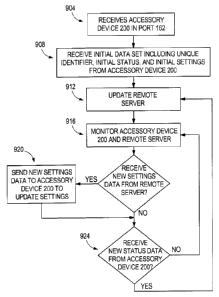
includes a step
904 in which the garage door opener 100 receives the accessory device 200 in
the port 162, as
described in detail above. In a step 908, the garage door opener 100 receives
the initial data set
850 including the unique identifier 854, the initial statuses 858, and the
initial settings 862. The
28
CA 2961221 2017-03-17
initial data set 850 may be received with the port identifier 848 as well. The
initial data set 850
is forwarded to the remote sever 950 (without processing) via the wireless
board 176 in a step
912. In other words, the wireless board 176 (and therefore garage door opener
100) acts as a
serial pass through device to transmit the data set 850 between the accessory
device 200 and the
remote server 950. The port identifier 848 may also be transmitted with the
initial data set to the
remote server 950. Once the data set 850 is uploaded to the remote server 950,
a peripheral
device 252 may download or otherwise access the data set 850 and furthermore
update the
settings 862. In step 916, the wireless board 176 monitors the accessory
device 200 for changes
in the status 858 and monitors the remote server 950 for changes in the
settings 862 (e.g., via
input from the peripheral device 252). In step 920, the garage door opener 100
determines if the
new settings 862 have been received from the remote server 950. If new
settings 862 are
received, the garage door opener 100 passes the new settings 862 to the
accessory device 200 to
update the settings of the accessory device 200 (step 922). For example, the
garage door opener
100 may pass the new settings 862 to the port identified by the port
identifier 848, which may be
transmitted with the new settings 862 by the remote server 950. As described
above, in response
to updated settings 862 received by one of the accessories 200, the accessory
200 may change its
operation (e.g., a light or component may be enabled or disabled, a level of
operation may be
changed, etc.). Whether or not new settings data 862 has been received, the
garage door opener
100 proceeds to step 924. In step 924, the garage door opener 100 determines
if new status data
858 is received from the accessory device 200. If new status data 858 is
received, the garage
door opener 100 updates the remote server 950 (step 912). If no new status
data 858 is received,
the garage door opener 100 continues to monitor the accessory device 200 and
the remote server
950 (step 916). In other embodiments, steps 920 and 924 may be reversed, or
accomplished
concurrently.
1001201 FIG. 32 illustrates a peripheral device communication method 1000 for
a peripheral
device (e.g., the peripheral device 252) to obtain status information from one
or more of the
accessory devices 200 of the garage door opener 100 and to update settings of
one or more of the
accessory devices 200. In step 1005, the peripheral device 252 receives the
initial data set 850
including the unique identifier 854, the initial statuses 858, and the initial
settings 862
information. The retrieval of the initial data set 850 may occur upon start-up
of a software
29
CA 2961221 2017-03-17
application (or, "app") executed on the peripheral device 252 that, for
example, includes sending
of an initial request to the remote server 950 for the initial data set 850.
[00121] In step 1010, at least a portion of the initial data set 850 is
displayed on the
peripheral device 252. For example, a screen of the peripheral device 252
illustrates the port 162
or 164 associated with the initial data set, the type of the accessory 200
coupled thereto
(determined based on the unique identifier 854), the initial status 858, and
the initial settings 862.
The type of the accessory 200 is determined based on the unique identifier
854, which may serve
as an index into a lookup table of unique identifiers matched to accessory
types. The lookup
table may further be associated with a graphic or icon that is then displayed
on the screen in
combination with a name (e.g., "fan") of the accessory 200. In one example, a
particular unique
identifier 854 indicates a lack of an accessory at an associated port, which
may also be displayed
on the display of the peripheral device 252 in step 1010.
[00122] In step 1015, the peripheral device 252 determines whether user input
has been
received that indicates a request to change an accessory setting. For example,
the peripheral
device 252 may include a touch screen display illustrating each coupled
accessory 200. The
peripheral device 252 may receive a user selection of one of the displayed
accessories, which
leads to a separate accessory screen particular to the type of accessory
selected. The accessory
screen illustrates the type of accessory, the settings of the accessory, and
the statuses of the
accessory (e.g., textually, graphically, or both) as determined based on the
obtained data set for
that accessory. Each setting may have a toggle (e.g., on/off), slider bar,
numerical input, radio
buttons, or other user input selectors that may be manipulated by a user to
provide a setting
update request received by the peripheral device 252.
[00123] When, in step 1015, the peripheral device 252 determines that user
input has been
received (e.g., via one of the user input selectors), the peripheral device
252 proceeds to step
1020, where the peripheral device 252 communicates the new setting to the
remote server 950.
The remote server 950 overwrites the previous setting stored in the data set
for the particular
accessory with the new setting. As described with respect to method 900, the
garage door opener
100 obtains the updated setting from the remote server 950, and, in turn,
provides the updated
setting to the particular accessory 200 to which the new setting is directed.
, =
CA 2961221 2017-03-17
[00124] The peripheral device 252 proceeds to step 1025 regardless of whether
user input is
received. In step 1025, the peripheral device 252 determines whether an update
to the data set
850 has occurred, such as a new status 858 or new unique identifier 854. When
an update to the
data set 850 has occurred, the peripheral device 252 returns to step 1010 to
display the new data
set 850 as described above. When an update to the data set 850 has not
occurred, the peripheral
device 252 returns to step 1015 to determine whether user input has been
received. Accordingly,
the peripheral device 252 may loop between steps 1015 and 1025 until either
the data set 850 is
updated or user input is received.
[00125] In some instances, a new setting 858 provided to one of the
accessories 200 will cause
a status update on the accessory 200, which is then provided to the remote
server 950 and
eventually displayed on the peripheral device (e.g., step 1010), providing
user feedback of a
successful settings update on the accessory.
[00126] In some embodiments, the data transmitted to/from the remote server
950 by/to the
peripheral device 252 and the garage door opener 100, may result from periodic
polling of data
by one or more of the remote server 950, the peripheral device 252, and the
garage door opener
100. For example, with reference to FIG. 32, the peripheral device 252 may
poll the remote
server 950 each time the step 1025 is reached in the method 1000. In some
embodiments, the
data transmitted to/from the remote server 950, to/from the peripheral device
252 and the garage
door opener 100, may result from pushing of data by one or more of the remote
server 950, the
peripheral device 252, the garage door opener 100 either periodically or in
response to changes
in the data to be transmitted (e.g., a unique identifier, a setting, and/or a
status). For example,
data (e.g., settings data) may be pushed from the peripheral device 252 to the
remote server 950
upon a status change (e.g., steps 1015 and 1020), and data (e.g., status data)
may be pushed to
the peripheral device 252 from the remote server 950 upon a status change
received from the
garage door opener 100.
[00127] While the method 900 and method 1000 of FIGS. 31 and 32, respectively,
are
generally described with respect to a single accessory 200, the methods and
steps therein may be
repeated (serially or concurrently) for each accessory 200 and/or port 162,164
of the garage door
opener 100. For example, with reference to the method 1000, when obtaining the
initial data set
31
=
CA 2961221 2017-03-17
in step 1005, the peripheral device may receive the initial data set for each
of the ports 162,164,
which then may be displayed in step 1010.
[00128] In some embodiments, the peripheral device 252, based on received user
input, may
be used to control the garage door opener 100 to drive the motor 112 to open
and shut the garage
door. For example, the peripheral device 252 may transmit an open or close
request, via the
remote server 950, to the wireless board 176. The wireless board 176, in turn,
controls the motor
112 in accordance with the request to open or shut the garage door.
Additionally, the garage
door opener 100 may use a motor 112 position sensor (e.g., Hall sensors or a
resolver) to
determine the status of the garage door as being either open, shut, or a
position between open and
shut. The garage door opener 100, via wireless board 176, may then communicate
the state of
the garage door to the peripheral device 252 for display to a user.
[00129] FIG. 33 illustrates one exemplary block diagram of the remote server
950 in further
detail. As illustrated, the remote server 950 includes a communications
circuit 1100, a memory
1105, and an electronic processor 1110 coupled by bus 1115. The communication
interface 1100
is coupled to the communication links 1130 and 1135 of FIG. 30 and enables the
electronic
processor 1100 (and, thereby, the remote server 950) to communicate with the
garage door
opener 100 and the peripheral device 252. The communication links 1130 may
include one or
more wired or wireless connections, networks, and protocols including, but not
limited to, a local
area network (LAN), the Internet, Wi-Fi, cellular, LTE, 3G, Bluetooth,
Ethernet, USB, and the
like. The memory 1105 stores the accessory information 875, as well as
operational data and
software. The electronic processor 1110 executes software, which may be stored
in the memory
1105, to carry out the functionality of the remote server 950 described
herein. For example, the
electronic processor 1110 reads and writes the accessory information 875 to
the memory 1105.
Although illustrated as a single server, the remote server 950 may be
implemented by one or
more servers co-located or located separately from one another and, for
instance, coupled by
various communication networks.
[00130] FIG. 34 illustrates one exemplary block diagram of the peripheral
device 252 in
further detail. As illustrated, the peripheral device 252 includes a
communications circuit 1150,
a memory 1155, and an electronic processor 1160, a display 1165, and user
input devices 1170
32
= I
CA 2961221 2017-03-17
coupled by bus 1175. The communication interface 1150 is coupled to the
communication link
1135 of FIG. 30 and enables the electronic processor 1160 (and, thereby, the
peripheral device
252) to communicate with the remote server 950 (and, thereby, the garage door
opener 100).
The electronic processor 1160 executes software, which may be stored in the
memory 1155, to
carry out the functionality of the peripheral device 252 described herein. For
example, the
electronic processor 1110 executes the steps of the method 1000 of FIG. 32.
The user input
devices 1170 include one or more push buttons, toggle switches, speakers, and
vibration
generators for receiving user input and providing user output. In some
embodiments, the display
1165 is a touch screen display and is part of the input/output devices 1170.
The display provides
visual output, such as shown in FIG. 29, regarding the garage door opener 100
and the
accessories 200.
1001311 FIG. 35 illustrates one exemplary block diagram of one of the
accessory devices
200 in detail. As illustrated, the accessory device 200 includes a controller
1200 having a
memory 1205 and an electronic processor 1210, one or more sensors 1215 (e.g.,
temperature
sensors, humidity sensors, and carbon monoxide sensors, etc.) and one or more
loads 1220 (e.g.,
indicators, speakers, a motor, a power relay, a park-assist laser light, a
light, and a compressor)
coupled by a bus 1225. The controller 1200 is coupled to the garage door
opener 100 via the
electrical mounting interface 400 to enable data communications between the
controller 1200
and the garage door opener 100 and to provide power to the accessory 200. In
particular, the
power supply 1230 receives conditions and filters power from the garage door
opener 100, and
provides the power to the other components of the accessory 200. The
controller 1200 executes
software, which may be stored in memory 1205, to carry out the function of the
accessory device
described herein. The memory 1205 may also store the data set 850 for the
accessory. The
particular sensors 1215, loads 1220, and functionality of the controller 1200
varies depends on
the type of accessory 200. In one example, the accessory device 200 is the
extension cord reel
220. The extension cord reel 220 includes the controller 1200 having the
memory and the
electronic processor 1210, and one or more loads 1220 (i.e., an AC output with
a relay). In this
example, the controller 1200 operates the relay of the load 1220 (i.e., the AC
output) to
selectively allow or prevent the delivery of electricity to power outlets 230
¨ that is, the
controller 1200 can turn the power outlets 230 on and off based on
communications received
from the garage door opener 100 or the peripheral device 252.
33
õ
CA 2961221 2017-03-17
[00132] FIG. 36 illustrates an alternative embodiment of a block
power diagram of the
garage door opener 100. The garage door opener 100 includes a terminal block
2202 configured
to receive power from an external power source 2204, such as a standard 120
VAC power outlet.
The terminal block 2202 directs power, via a transformer 2208, to a garage
door opener (GDO)
board 2210 for supply to components thereof as well as a motor 2211 (used to
drive a drive
mechanism 2116 in a similar manner as described above), LEDs 2214 (of the
light unit 2152),
and garage door sensors 2216. The terminal block 2202 further directs power
via the transformer
2208 to a wireless board 2220 and components thereof, as well as a wired
keypad 2222 and
module ports 2223. The terminal block 2202 also directs power to a battery
charger 2224 and to
AC ports 2228, which may be referred to as pass-through outlets. The module
ports 2223 are
configured to receive the various accessory devices 200, such as the speaker,
the fan, the
extension cord reel, the parking assist laser, the environmental sensor, the
flashlight, and a
security camera. One or more of the accessory devices 200 are selectively
attachable to and
removable from the garage door opener 100, and may be monitored and controlled
by the garage
door opener 100 as previously described above.
[00133] The wireless board 2220 includes a wireless
microcontroller 2240, among other
components. Additionally, similar to the wireless board 176, and with
reference to FIG. 6, the
wireless board 2220 is configured to communicate with the network hub 948, the
wireless
network 952 (e.g., including the remote server 950), the peripheral device
252, the wall-mounted
keypad 2222, and the accessory devices 200. The GDO board 2210 includes, among
other
components, a garage door opener (GDO) microcontroller 2244 and a radio
frequency (RF)
transceiver 2246. The communication diagram of FIG. 7 similarly applies to the
diagram of FIG.
36 in that, for example, the GDO board 2210 may substitute for the GDO board
168, and the
wireless board 2220 may substitute for the wireless board 176. Accordingly,
the GDO board
2210 is in communication with the wireless board 2220 (e.g., via a
multiplexer) and is
configured to actuate operation of the motor 2221 based on communications
received from, for
example, the wireless board 2220, the peripheral device 252, the door sensors
700, the car
remote 253, and the outdoor keypad 248.
[00134] The GDO board 2210 and the wireless board 2220 may also
be referred to as a
controller of the garage door opener, with the controller including an
electronic processor and
34
CA 2961221 2017-03-17
memory storing instructions. The electronic processor executes the
instructions to carry out the
functionality of the GDO board 2210 and the wireless board 2220 described
herein and, more
generally, the control functionality of the garage door opener 100 described
herein. An example
of a similarly configured controller having an electronic processor and
memory, albeit for a
battery pack, is illustrated in FIG. 10 as controller 1355.
[00135] Various features of the invention are set forth in the following
claims.