Note: Descriptions are shown in the official language in which they were submitted.
313067-4
TRUNK LINE MANIFOLD SYSTEM
BACKGROUND
1. Field of the Invention
[002] The present disclosure relates to fluid delivery systems and in
particular to
manifolds for delivering fluids under pressure.
2. Description of Related Art
[003] During well site operations, such as hydraulic fracturing, fluid is
directed to
pumper trucks for pressurization and subsequent injection into a wellbore.
Tubular
connections are used to tie low pressure fluid sources to pump inlets and
subsequently to
inject high pressure fluid into the wellbore. Often, individual tubulars, such
as pipes or
flexible tubing, are utilized to independently coupled each pumper truck to
and from each
fluid source, leading to complicated tubing systems at the well site that are
subject to
vibration, pressure drop, and the like. It is now recognized that improved
methods of
connecting fluid systems are desired.
SUMMARY
[004] Applicants recognized the problems noted above herein and conceived
and
developed embodiments of systems and methods, according to the present
disclosure, for
trunk line manifolds.
1
Date Recue/Date Received 2022-02-23
CA 2961310 2017-03-20
313067-4
[005] In an embodiment an apparatus for transporting fluids includes a
chassis having
wheels and a hitch, the hitcla'arranged at a first end and the wheels arranged
at a second
end. The apparatus also includes a high pressure trunk line extending along a
length of the
chassis, the high pressure trunk line having a plurality of high pressure
inlets for coupling
one or more lines directing high pressure fluids into the high pressure trunk
line.
Furthermore, the apparatus includes one or more low pressure lines, the one or
more low
pressure lines arranged proximate the high pressure trunk line and having a
plurality of
suction outlets along the length of the chassis. Also, the apparatus includes
an inlet
manifold positioned at the second end of the chassis, the inlet manifold being
coupled to
the one or more low pressure lines to supply a low pressure fluid to the one
or more low
pressure lines.
[006] In another embodiment a system for directing fluid to a well site
includes one
or more pumper trucks at a well site where hydraulic fracturing is to be
performed. The
system also includes a wellbore at the well site, the wellbore including an
injection spool
for injecting high pressure fluid into the wellbore. The system includes a
trailer manifold.
The trailer manifold includes a high pressure trunk line. The high pressure
trunk line
receives pressurized fluid from the one or more pumper trucks at high pressure
inlets
arranged along a length of the high pressure trunk line. The trailer manifold
also includes
a low pressure line arranged proximate the high pressure trunk line, the low
pressure line
receives low pressure fluid different from the pressurized fluid via an inlet
manifold.
Additionally, the trailer manifold includes a chassis supporting the high
pressure trunk line
and the low pressure line, the chassis includes a hitch arranged at a first
end and wheels
arranged at a second end proximate the inlet manifold.
[0071 In an embodiment a system for directing fluid to a well site includes
one or
more pumps, the pumps receiving a low pressure fluid and outputting a high
pressure fluid.
The system also includes a wellbore at the well site, the wellbore including
an injection
spool for injecting the high pressure fluid into the wellbore. The system also
includes a
trailer manifold. In certain embodiments, the trailer manifold includes a high
pressure
trunk line. The high pressure trunk line receives the high pressure fluid from
the one or
2
CA 2961310 2017-03-20
313067-4
more pumps at high pressure inlets arranged along a length of the high
pressure trunk line.
The trailer manifold also includes a chassis supporting at least a portion of
the high pressure
trunk line, the chassis including a hitch arranged at a first end and wheels
arranged at a
second end.
BRIEF DESCRIPTION OF DRAWINGS
[008] The foregoing aspects, features, and advantages of the present
disclosure will
be further appreciated when considered with reference to the following
description of
embodiments and accompanying drawings. In describing the embodiments of the
disclosure illustrated in the appended drawings, specific terminology will be
used for the
sake of clarity. However, the disclosure is not intended to be limited to the
specific terms
used, and it is to be understood that each specific term includes equivalents
that operate in
a similar manner to accomplish a similar purpose.
[009] FIG. 1 is a schematic top plan view of an embodiment of a well site,
in
accordance with embodiments of the present disclosure;
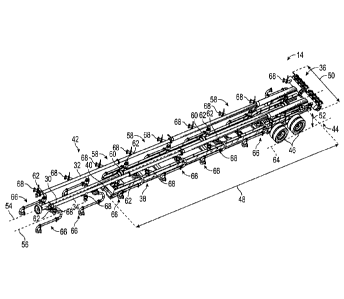
[0010] FIG. 2 is a front perspective view of an embodiment of a trailer
manifold, in
accordance with embodiments of the present disclosure;
[0011] FIG. 3 is a rear perspective view of the trailer manifold of FIG. 2,
in accordance
with embodiments of the present disclosure;
[0012] FIG. 4 is a partial front perspective view of the trailer manifold
of FIG. 2, in
accordance with embodiments of the present disclosure;
[0013] FIG. 5 is a partial front perspective view of the trailer manifold
of FIG. 2, in
accordance with embodiments of the present disclosure;
[0014] FIG. 6 is a side elevational view of the trailer manifold of FIG. 2,
in accordance
with embodiments of the present disclosure;
3
CA 2961310 2017-03-20
31 3067-4
[0015] FIG. 7 is a partial side elevational view of an embodiment of a
trailer manifold,
in accordance with embodiments of the present disclosure;
[0016] FIG. 8 is a top plan view of the trailer manifold of FIG. 2, in
accordance with
embodiments of the present disclosure;
[0017] FIG. 9 is a front perspective view of an embodiment of a trailer
manifold, in
accordance with embodiments of the present disclosure;
[0018] FIG. 10 is a cross-sectional top plan view taken along line 10-10,
in accordance
with embodiments of the present disclosure; and
[0019] FIG. 11 is a schematic top plan view of a piping arrangement, in
accordance
with embodiments of the present disclosure.
DETAILED DESCRIPTION
[0020] The foregoing aspects, features, and advantages of the present
disclosure will
be further appreciated when considered with reference to the following
description of
embodiments and accompanying drawings. In describing the embodiments of the
disclosure illustrated in the appended drawings, specific terminology will be
used for the
sake of clarity. However, the disclosure is not intended to be limited to the
specific terms
used, and it is to be understood that each specific term includes equivalents
that operate in
a similar manner to accomplish a similar purpose.
[0021] When introducing elements of various embodiments of the present
disclosure,
the articles "a", "an", "the", and "said" are intended to mean that there are
one or more of
the elements. The terms "comprising", "including", and "having" are intended
to be
inclusive and mean that there may be additional elements other than the listed
elements.
Any examples of operating parameters and/or environmental conditions are not
exclusive
of other parameters/conditions of the disclosed embodiments. Additionally, it
should be
understood that references to "one embodiment", "an embodiment", "certain
embodiments", or "other embodiments" of the present disclosure are not
intended to be
4
CA 2961310 2017-03-20
313067-4
interpreted as excluding the existence of additional embodiments that also
incorporate the
recited features. Furthermore, reference to terms such as "above", "below",
"upper",
"lower", "side", "front", "back", or othcr terms regarding orientation or
direction are made
with reference to the illustrated embodiments and are not intended to be
limiting or exclude
other orientations or directions.
[0022] Embodiments of the present disclosure include a truck line manifold
for
distributing fluid at a well site. In certain embodiments, the trunk line
manifold includes a
chassis that supports a high pressure trunk line and a pair of low pressure
lines. In
operation, the low pressure lines direct low pressure fluid through suction
outlets to pumper
trucks. These pumper trucks pressurize the fluid for later use at the well
site and direct the
pressured, high pressure fluid back to the high pressure trunk line. In
certain embodiments,
the high pressure trunk line includes high pressure inlets that direct the
high pressure fluid
into the trunk line. The high pressure inlets are arranged at angles relative
to the high
pressure trunk line to facilitate mixing and reduce turbulence within the
trunk line. The
high pressure trunk line includes an outlet for directing the high pressure
fluid to a wellbore
for injection, for example, during hydraulic fracturing operations. In this
manner, multiple
high pressure flow lines may be reduced into a single line, thereby
simplifying well site
configurations and reducing pressure drop, vibration, turbulence, and wash out
in fluid
lines.
[0023] FIG. it is a schematic top plan view of a well site 10 including
pumper trucks
12 fluidly coupled to a trailer manifold 14. In the illustrated embodiment,
there are 14
pumper trucks 12, but it should be appreciated that there may be more of fewer
pumper
trucks 12. Moreover, while the pumper trucks 12 are illustrated in FIG. 1, in
certain
embodiments pumps, such as skid mounted pumps, may also be utilized. In
operation, the
pumper trucks 12 receive a low pressure fluid from the trailer manifold 14 via
an inlet line
16 and thereafter pressurize the fluid and direct that fluid toward the
trailer manifold 14 via
an outlet line 18. The inlet and outlet line 16, 18 may be tubulars formed
from metal or
other material sufficient for handling the pressure of the fluid in the lines.
As will be
CA 2961310 2017-03-20
313067-4
described below, the lines 16, 18 may be coupled to the trailer manifold 14
via flanged
connections, or other connections, to facilitate connection of the lines at
the well site 10.
[0024] During hydraulic fracturing operations, a fracturing fluid, such as
water, is
mixed with a proppant, such as silica sand, to stimulate wellbore operations.
For example,
the fracturing fluid and proppant are injected into a wellbore 20 at high
pressures via an
injection spool. This high pressure injection may generate fissures in the
areas surrounding
the wellbore 20. The proppant holds open the fissures to thereby enable oil
and gas to
freely flow to the wellbore 20 via the fissures.
[0025] FIG. 2 is a front perspective view of an embodiment of the trailer
manifold 14.
As shown, the trailer manifold 14 includes a high pressure trunk line 30
(e.g., trunk line,
high pressure line, etc.), a pair of low pressure lines 32, 34, an inlet
manifold 36, and a
chassis 38. Moreover, a hitch 40 is positioned at a first end 42 of the
chassis 38. The hitch
40 at the first end 42 is opposite the inlet manifold 36 at a second end 44 of
the chassis 38.
The hitch 40 enables attachment of the trailer manifold 14 to a prime mover,
such as a
truck. As such, the trailer manifold 14 may be easily moved from location to
location along
traditional roadways. In the illustrated embodiment, the chassis 38 has wheels
46
proximate to the second end 44. As shown, the chassis 38 maybe referred to as
tandem
axle and the dimensions may be particularly selected to enable transportation
along
roadways without having fees for excessive length, width, height, or weight.
For example,
in certain embodiments, a length 48 may not exceed approximately 16.1 meters
(approximately 53 feet), a width 50 may not exceed approximately 2.5 meters
(approximately 8.5 feet), and a height 52 may not exceed approximately 4.1
meters
(approximately 13.5 feet). Furthermore, the chassis 38 may be equipped with
systems and
controllers to enable operation on roadways, such as anti-lock brakes, air
systems, parking
brakes, LED road lights, and/or CMVSS/FMVSS approved modular harnesses.
However,
it should be appreciated that the chassis 38 may be omitted in certain
embodiments and the
high pressure trunk line 30, and related components, may be mounted onto one
or more
skids or other type of platform. Therefore, components of the chassis 38 such
as pipe racks
or lifts may also be incorporated into the one or more skids or platform.
6
CA 2961310 2017-03-20
313067-4
[0026] In the illustrated embodiment, the high pressure trunk line 30
extends along a
central portion of the chassis 38 and a trunk line axis 54 is substantially
aligned with a
chassis axis 56. In other words, the trunk line 30 may be centered on the
chassis 38, thereby
enabling even weight distribution for movement of the trailer manifold 14. On
each side
proximate the trunk line 30 are the low pressure lines 32, 34. In certain
embodiments the
low pressure lines 32, 34 are evenly spaced from the trunk line 30. As such,
the trailer
manifold 14 may be substantially symmetrical about the chassis axis 56.
However, as noted
above, embodiments of the present disclosure may include mounting the high
pressure
trunk line 30, the low pressure line 32, 34, and/or the inlet manifold 36 on
one or more
skids or platforms. Accordingly, references to the chassis length 48, chassis
axis 56, and
the like are applicable to embodiments include the one or more skids. For
example, the
chassis length 48 may correspond to a skid length.
[0027] As will be described in detail below, the trunk line 30 includes a
plurality of
trunk line segments 58, each having a connector 60 at the ends, such as a
flange. In
embodiments where the trunk line segments 58 include flanged connectors, the
segments
58 may be easily replaced, for example, due to washing out. As such,
components of the
trunk line 30 and/or the trailer manifold 14 may be easily replaced, thereby
enabling faster
repairs and more flexibility at well sites. In the illustrated embodiment, the
trunk line 30
further includes high pressure inlets 62 for connecting to the outline lines
18 of the pumper
trucks 12. The high pressure inlets 62 are arranged along the sides of the
trunk line 30, in
the illustrated embodiment, such that the high pressure inlets 62 are
substantially parallel
to a ground plane 64. Furthermore, as shown, the high pressure inlets 62 are
coupled to
spools 66, such as safety irons, to facilitate connection to the outlet lines
18. In the
illustrated embodiments, the spools 66 have an "S" configuration. Moreover, as
shown,
the connections leading to the high pressure inlets 62 may all be flanged,
thereby enabling
easy connections and replacement of components. Moreover, it should be
appreciated that
other components, such as check valves, pressure relief valves, flow valves
(manual or
actuated) may be arranged between the high pressure inlets 62 and the spools
66 or
upstream of the spools 66. As will be described below, in the illustrated
embodiment, a
7
CA 2961310 2017-03-20
313067-4
portion of the trunk line 30 is extending off of the chassis 38 in a
cantilevered fashion. This
configuration increases the flexibility of use for the trailer manifold 14, as
well as provides
options for connecting components to the trunk line 30.
[00281 The trailer manifold 14 also includes the low pressure lines 32, 34.
The low
pressure line 32, 34 include suction outlets 68 for directing low pressure
fluids to the
pumper trucks 12 along the inlet lines 16. The illustrated embodiment includes
20 suction
outlets 68, however, in other embodiments, there may be more or fewer suction
outlets 68.
Moreover, each low pressure line 32, 34 may not include the same number of
suction
outlets 68. For example, the low pressure line 32 may have more or fewer
suction outlets
68 than the low pressure line 34. The low pressure lines 32, 34 run the length
48 of the
chassis 38 and also extend off of the first end 42 of the chassis 38 in a
cantilevered fashion.
Moreover, each low pressure line 32, 34 is fluidly coupled to the inlet
manifold 36, which
supplies fluid for later use by the pumper trucks 12.
100291 FIG. 3 is a rear perspective view of the trailer manifold 14. In the
illustrated
embodiment, the inlet manifold 36 includes 12 fluid inlets 80, however, in
certain
embodiments, the inlet manifold 36 may include more or fewer fluid inlets 80.
As
described above, the inlet manifold 36 receives fluid, such as fracking fluid,
for distribution
to the low pressure lines 32, 34 for subsequent use by the pumper trucks 12.
The inlet
manifold 36 is arranged at the second end 44 of the chassis 38.
[00301 In the illustrated embodiment, the low pressure lines 32, 34 are
arranged at a
higher elevation, relative to the ground plane 64, than the high pressure
trunk line 30.
However, it should be appreciated that, in other embodiments, the high
pressure trunk line
30 may be at a higher elevation or an equal elevation to the low pressure
lines 32, 34. The
position of the lines 30, 32, 34 relative to one another may be particularly
selected to
accommodate the well site 10 configuration. That is, the relative locations of
the lines 30,
32, 34 may be particularly selected to facilitate connections to other
components at the well
site 10. In certain embodiments, the chassis 38 includes one or more supports
82 for
supporting the high pressure trunk line 30 and/or low pressure lines 32, 34.
8
CA 2961310 2017-03-20
313067-4
[0031] As shown in FIG. 3, the suction outlets 68 are arranged at an angle,
relative to
the low pressure line 34, in a direction toward the first end 42. In other
words, as fluid
flows from the inlet manifold 36 through the low pressures lines 32, 34 in a
direction 84
represented by the arrow, the suction outlets 68 are positioned at the angle
to direct the
fluid through the suction outlets 68 along the direction 84 that the fluid is
flowing, thereby
reducing friction and turbulence of the fluid as the fluid is directed out of
the suction outlets
68 and to the pumper trucks 12. It should be appreciated that, in other
embodiments, the
suction outlets 68 may be arranged at different positions, such as
perpendicular to the lines
32, 34, at a bottom of the line 32, 34, at a top of the lines 32, 34, or at
any other reasonable
location and orientation.
[0032] In the illustrated embodiment, the low pressure lines 32, 34 include
the
connectors 60. In certain embodiments, the connectors 60 may be flanged,
threaded,
clamped, or any other suitable connection. As described above, using a flanged
or clamped
connection enables faster connections while also providing metal to metal
sealing surfaces
for the components.
[0033] Referring to the high pressure trunk line 30, the spools 66 are
illustrated as
extending off of the high pressure inlets 62. In the illustrated embodiment,
the spools 66
are arranged in a variety of configurations to enable coupling of the outlet
lines 18 to the
trunk line 30. As shown, the spools 66 are in the "S" configuration and
including
connectors 60 and individual, replaceable spool components. As a result, in
the event a
portion of the spool 66 is washed out or damaged, the component may be readily
replaced.
Moreover, in the illustrated embodiment, threaded connections may be reduced
and/or
eliminated, thereby improving reliability with the connections.
[0034] In certain embodiments, the chassis 38 includes a leg 86 that may be
retractable.
The leg 86 is arranged to extend down to the ground plane 64 when the chassis
38 is not
being hauled by the prime mover and to retract when the chassis 38 is being
hauled by the
prime mover. In this manner, the leg 86 may support the chassis 38 and provide
additional
stability during operations at the well site 10.
9
CA 2961310 2017-03-20
313067-4
[0035] FIG. 4 is a front perspective view of the trailer manifold 14 in
which the low
pressure lines 32, 34 have been removed for clarity. As described above, the
high pressure
trunk line 30 is arranged along the length 48 of the chassis 38 and further
extends off of
the first end 42. In the illustrated embodiment, the trunk line 30 has a trunk
line length 90
that is greater than the chassis length 48. Moreover, each trunk line segment
58 has a
segment length 92. As will be appreciated, the sum of the segment lengths 92
is equal to
the trunk line length 90. It should be appreciated that, when moving the
trailer manifold
14, the trunk line segment 58a may be removed and positioned on the chassis
38, for
example, in a pipe rack, to enable coupling to the prime mover and
transportation to a
different location. In the illustrated embodiment, the high pressure inlets 62
are arranged
at an angle 100 relative to the trunk line axis 54. In operation, fluid (e.g.,
high pressure
fluid) flows through the outlet lines 18 from the pumper trucks 12 and into
the high pressure
trunk line 30 via the high pressure inlets 62. After entering the high
pressure trunk line 30,
the fluid is directed toward the outlet 102, moving in the downstream
direction 104, as
represented by the arrow. Arranging the high pressure inlets 62 at the angle
100 enables
the fluid to enter the high pressure trunk line 30 in a direction
substantially parallel to the
downstream direction 104. As a result, there is a reduced likelihood of
impingement on
the opposite side of the high pressure trunk line 30. Moreover, friction may
be reduced
because the fluid will not turn or change direction with such severity as, for
example, an
inlet perpendicular to the trunk line 30. Furthermore, as will be described
below,
turbulence may be reduced by positioning the high pressure inlets 62 at the
angle 100. The
angle 100 may be any suitable angle relative to the trunk line axis 54, such
as approximately
degrees, approximately 20 degrees, approximately 30 degrees, approximately 40
degrees, approximately SO degrees, approximately 60 degrees, approximately 70
degrees,
approximately 80 degrees, or any other suitable angle.
[0036] As described above, the spools 66 are coupled to the high pressure
inlets 62 via
a flanged or clamped connection, in the illustrated embodiment. As a result,
threaded
fittings proximate the high pressure trunk line 30 may be reduced or
eliminated.
Furthermore, the spools 66 illustrated in FIG. 4 include the "S" shaped bend
to enable
CA 2961310 2017-03-20
313067-4
different configurations and directions to ease coupling at the well site 10.
For example,
rigid tubing or hosing may form the outlet line 18. If the outline line 18 is
routed in such
a way that it is difficult to connect to the spools 66, the configuration
and/or the position
of the spools 66 may be easily modified to enable connections, thereby
reducing time to
prepare the system for use. Additionally, other components may be included
along the
high pressure inlets 62, such as instrumentation systems and tie-ins, check
valves, or the
like. For example, check valves may be arranged upstream of the high pressure
inlets 62,
and in certain embodiments upstream of the spools 66, to block the high
pressure trunk line
30 from draining when the pumper trucks 12 are disconnected. These check
valves may
be ball check valves, diaphragm check valves, swing check valves, stop-check
valves, lift-
check valves, in-line check valves, duckbill valves, or pneumatic non-return
valves.
Moreover, the check valves may be manual or actuated. Furthermore, other
systems may
also be incorporated to correspond with the high pressure trunk line 30, such
as over
pressure protection mechanisms. For example, the over pressure protection
mechanisms
could include pressure relief valves (e.g., relief valves, safety valves,
etc.), burst discs (e.g.,
rupture discs) or the like. For example, the pressure relief valve may be
coupled to the
high pressure line to safeguard again pressure spikes. In certain embodiments,
the outlet
of the over pressure protection mechanism may direct over-pressured fluid to a
containment
vessel or other suitable location.
[0037] In the
illustrated embodiment, the trailer manifold 14 includes a single high
pressure trunk line 30, thereby reducing or eliminating drawbacks associated
with multiple
high pressure lines at the well site 10. For example, in systems that include
multiple high
pressure lines coupling at the well site 10, for example, at the tree or
injection point,
significant vibration may occur from the flow coming in at different
directions and/or
angles. Moreover, wash out may occur due to the turbulence generated by
combining
different flows together at the tree or injection point. Furthermore,
multiple, smaller lines
suffer increased pressure drop, thereby reducing the effectiveness of the
fracturing
operation. In sharp contrast, the single high pressure trunk line 30 of the
illustrated
embodiment has a diameter 106 sufficient to provide fracturing fluid to the
well site 10 that
11
CA 2961310 2017-03-20
313067-4
is the equivalent or greater than multiple smaller lines. Furthermore, the
high pressure
trunk line 30 has the single outlet 102 and reduces turbulence within the high
pressure trunk
line 30 due to the configuration of the high pressure inlets 62. As a result,
there is less
turbulence, less pressure drop, and reduced washout at the injection point.
Furthermore,
as described above, the connectors 60 may be flanged or clamped, thereby
forming metal
to metal seals between components to reduce the likelihood of leaks and reduce
maintenance events.
[0038] FIG. 5 is a front perspective view of the trailer manifold 14 in
which the high
pressure trunk line 30 has been removed for clarity. In the illustrated
embodiment, the low
pressure lines 32, 34 are arranged along the length 48 of the chassis 38 and
extend away
from the first end 42. In the illustrated embodiment, the low pressure lines
32, 34 have a
low pressure line length 120. Furthermore, as shown in FIG. 5, the low
pressure lines 32,
34 are formed from low pressure segments 122, each having a low pressure
segment length
124. The segments 122 include the connectors 60 at the end to facilitate
replacement or
removal of sections of the low pressure lines 32, 34. For example, the
connectors 60 may
be flanged or clamped to facilitate quick and efficient connections and
disconnections. In
the illustrated embodiment, multiple suction outlets 68 are arranged on each
low pressure
segment 122. However, in other embodiments, each low pressure segment 122 may
include a single suction outlet 68. Each of the low pressure lines 32, 34 are
coupled to the
inlet manifold 36, which directs fluid into each of the lines 32, 34. As
described above, the
suction outlets 68 are utilized to direct low pressure fluid to the pumper
trucks 12 via the
inlet lines 16. The suction outlets 68 are arranged at an angle 126 with
respect to the chassis
axis 56 to thereby facilitate directing the fluid out of the line 32, 34
through the suction
outlets 68. For example, as described above, by pointing the suction outlets
68 along the
direction of fluid flow 84, turbulence, wash out, and vibration may be
decreased. In certain
embodiments, the supports 82 are utilized to support the low pressure lines
32, 34, but the
supports 82 have also been removed for clarity.
[0039] FIG. 6 is a side elevational view of the trailer manifold 14. In the
illustrated
embodiment, the high pressure trunk line 30 is shown extending along a length
48 of the
12
CA 2961310 2017-03-20
313067-4
chassis 38 and further extending beyond the first end 42. That is, the trunk
line length 90
is greater than the chassis length 48. By extending beyond the chassis 38, the
configuration
at the well site 10 includes additional options because, for example, the
extending trunk
line segment 58a may be supported by a pipe stand, hydraulic jack, or any
other reasonable
structure. Moreover, in certain embodiments, the outlet 102 may be tied
directly into the
injection point which provides sufficient support for the trunk line segment
58a.
[0040] In the illustrated embodiment, the low pressure line 32 is at a
higher elevation,
relative to the ground plane 64, than the high pressure trunk line 30.
However, it should
be appreciated that, in other embodiments, the high pressure trunk line 30 may
be at an
elevation equal to or greater than the low pressure line 32. FIG. 6
illustrates the variety of
configurations that the spools 66 may be positioned in. For example, the spool
66a is
arranged such that an inlet is positioned at a lower elevation than the high
pressure trunk
line 30. In contrast, the spool 66b is arranged such that an inlet is
positioned at a higher
elevation than the high pressure trunk line 30. In this manner, different
configurations of
the spools 66 may facilitate making connections to the high pressure trunk
line 30.
[0041] FIG. 7 is a partial side elevational view of the trailer manifold
14. In the
illustrated embodiment, the first end 42 is illustrated while the second end
44 is removed
for clarity. As described above, trunk line segments 58 are connected via the
connectors
60. In the illustrated embodiment, the trunk line segment 58b includes two
sets of high
pressure inlets 62. However, as described above, in certain embodiments each
trunk line
segment 58 may include a single pair of high pressure inlets 62, or a single
high pressure
inlet 62. As shown, the trunk line segment 58a extends beyond the chassis 38.
Moreover,
in the illustrated embodiment, the low pressure line 34 is arranged at an
elevation lower
than the high pressure trunk line 30. But as described above, in other
embodiments the
high pressure trunk line 30 may be at the same elevation or lower than the low
pressure
line 34.
[0042] FIG. 8 is a top plan view of the trailer manifold 14. In the
illustrated
embodiment, the chassis axis 56 is substantially aligned with the trunk line
axis 54. In
13
CA 2961310 2017-03-20
313067-4
other words, the high pressure trunk line 30 is substantially centered on the
chassis 38.
Moreover, the low pressure line 32, 34 are arranged substantially
symmetrically about the
trunk line 30. As will be appreciated, this arrangement may facilitate hauling
of the trailer
manifold 14 on roadways due to the balanced weight configuration. Moreover,
vibration
may be reduced due to the balanced configuration. In the illustrated
embodiments, the high
pressure inlets 62 are illustrated at the angle 100 described above to thereby
direct the high
pressure fluid along the flow direction 104. Additionally, the high pressure
inlets 62 extend
to the sides of the high pressure trunk line 30 such that the high pressure
inlets 62 are
substantially parallel to the ground plane 64. However, it should be
appreciated that, in
other embodiments, the high pressure inlets 62 may be arranged at other
positions around
the circumference of the trunk line 30. Furthermore, as illustrated, the
spools 66 are
arranged to extend outwardly from the low pressure lines 32, 34. However, it
should be
appreciated that, in certain embodiments, the spools 66 may be substantially
aligned with
the low pressures lines 32, 34 or positioned inward from the low pressure
lines 32, 34.
Furthermore, as shown in FIG. 8, the suction outlets 68 are arranged at the
angle 122 to
facilitate directing the low pressure fluid to the pumper trucks 12.
[00431 FIG. 9 is a
front perspective view of the trailer manifold 14 in which the trunk
line segment 58a has been removed and stacked on the chassis 38. As described
above, in
certain embodiments the trunk line segment 58a will end beyond the first end
42 of the
chassis 38 when coupled to the trunk line segment 58b. In operation, this
provides
flexibility to the layout of the well site 10. However, during hauling
operations, the trunk
line segment 58a is removed to enable the hitch 40 to couple to the prime
mover. In the
illustrated embodiment, the trunk line segments 58a, 58b can be coupled via
the connectors
60. As a result, the segment 58a, 58b can be quickly disconnected and the
trunk line
segment 58a may be stored on the chassis 38 for transportation. In certain
embodiments,
the chassis 38 includes a pipe rack 130 for supporting the trunk line segment
58a.
Moreover, in certain embodiments, the chassis 38 may further include a lift
132 to facilitate
removal and storage of the trunk line segment 58a. For example, the lift 132
may be
positioned to articulate along the length 48 of the chassis 38. In the
illustrated embodiment,
14
CA 2961310 2017-03-20
313067-4
the lift 132 is a type of crane or suspended gripper that enables engagement
of the trunk
line segment 58a. It should be appreciated that, in certain embodiments, the
lift 132 may
not be coupled to the chassis 38. For example, the lift 132 may be separate
equipment at
the well site 10 that is utilized when desired.
[0044] Storing the trunk line segment 58a on the chassis 38 leads to a more
compact,
streamlined trailer manifold 14. For example, in embodiments where the extra
length of
the trunk line segment 58a is not used, the trunk line segment 58a may remain
on the chassis
38, thereby reducing the number of connections being made to the trailer
manifold 14.
Moreover, when not in use, the pipe rack 30 can hold replacement parts or the
like to
facilitate operation of the trailer manifold 14.
[0045] FIG. 10 is a top plan cross-sectional view taken along line 10-10.
In the
illustrated embodiment, the high pressure inlets 62 are arranged on the high
pressure trunk
line 30 at the angle 100. As described above, the high pressure inlets 62 are
positioned at
the angle 100 to facilitate mixing in the trunk line 30 to thereby reduce
turbulence when
the fluid is injected at the well site 10. Furthermore, positioning the high
pressure inlets
62 at the same angle 100 facilitates contact of the fluid within the trunk
line 30 to reduce
impingement on the trunk line 30. In the illustrated embodiment, the high
pressure inlet
62a directs a fluid represented by the arrow 140a toward the fluid 140b
directed into the
trunk line 30 via the high pressure inlet 62b. As shown, the fluid streams
140a, 140b
contact at a contact point 142. This contact point 142 reduces the eddies in
the fluid and
further directs the force of the fluid streams 140a, 140b away from the wall
of the trunk
line 30 by dissipating the force at the contact point 142. As a result, the
turbulence in the
flow is reduced downstream as the fluid streams 140a, 140b join to form the
fluid stream
140c moving in the flow direction 104.
[0046] FIG. 11 is a schematic top plan view of the trailer manifold 14
illustrating the
high pressure trunk line 30 and low pressure lines 32, 34. As described above,
in certain
embodiments, the trunk line 30 is formed by trunk line segments 58 that are
coupled
together via the connectors 60. Furthermore, in certain embodiments, the low
pressures
CA 2961310 2017-03-20
313067-4
lines 32, 34 are formed by low pressure segments 122 coupled together via the
connectors
60. In the illustrated embodiment, the high pressure trunk line 30 is formed
by six trunk
line segments 58 each having a pair of high pressure inlets 62. As a result,
if one section
of the high pressure trunk line 30 is damaged or needs to be repaired, the
individual segment
58 may be removed while the remaining portions are reused, thereby reducing
the cost of
maintenance. Additionally, in the illustrated embodiment, each low pressure
segment 124
includes a single suction outlet 68. In a similar manner to the trunk line 30,
the low pressure
segments 124 may also be individually removed and replaced during maintenance
operations. As described above, the connectors 60 may be flanged or clamped to
provide
additional sealing capacity and reduce the likelihood of leaks.
[0047] As described in
detail above the trailer manifold 14 includes the high pressure
trunk line 30 for collecting and distributing high pressure fluid from one or
more pumper
trucks 12 to the wellbore 20. In certain embodiments, the high pressure trunk
line 30 is
positioned on the chassis 38 and includes the high pressure inlets 62 to
direct the high
pressure fluid into the trunk line 30. Furthermore, in certain embodiments,
the high
pressure inlets 62 are arranged at angles relative to the trunk line 30 to
thereby facilitate
mixing and settling of the high pressure fluid upstream of the wellbore 20,
thereby reducing
turbulence and potential wash out during injection. Additionally, the trailer
manifold 14
includes the inlet manifold 36 for supplying low pressure fluid to the low
pressure lines 32,
34. In certain embodiments, the low pressure lines 32, 34 include the suction
outlets 68 to
provide low pressure fluid to the pumper trucks 12. Certain embodiments of the
system
include flanged or clamped connections that enable faster connections as well
as increased
flexibility regarding maintenance operations. For example, in embodiments
where the high
pressure trunk line 30 is formed from the trunk line segments 58, if a certain
segment 58
was undergoing maintenance operations, the remaining segments 58 could be
reused. In
this manner, high pressure fluid may be collected and provided to the wellbore
20 with
reduced piping complexity at the well site 10, reduced vibration, reduced
friction, reduced
pressure drop, and reduced turbulence.
16
313067-4
[0048] The
foregoing disclosure and description of the disclosed embodiments is
illustrative and explanatory of the embodiments of the invention. Various
changes in the
details of the illustrated embodiments can be made within the scope of the
appended claims
without departing from the scope of the disclosure. The embodiments of the
present
disclosure should only be limited by the following claims and their legal
equivalents.
17
Date Recue/Date Received 2022-02-23