Note: Descriptions are shown in the official language in which they were submitted.
CA 02961696 2017-03-16
WO 2016/049002 PCT/US2015/051412
AUTOMATIC MAPPING AND HANDLING PIM AND OTHER UPLINK
INTERFERENCES IN DIGITAL DISTRIBUTED ANTENNA SYSTEMS
Background
The worldwide in-building coverage market (IBW), or Distributed antenna
system (DAS), as it is frequently called, has been constantly growing in the
past few
years. It is quickly becoming the major arena in which mobile operators'
revenues are
generated. Most of the calls and data transfers are now generated inside
buildings and
constitute around 80 % of the operators' revenues.
In parallel to that, and due to the intensive use of smart phones, tablets,
etc.,
data carrying capacity is quickly becoming a valuable and scarce resource. The
demand for capacity has been constantly growing at a huge rate of around 100%
per
year. This means that a DAS system installed today will require twice the
capacity a
year from now and will require 8 times more capacity three years from now.
The aforesaid facts are valid not only for indoor DAS but also for outdoor
DAS's particularly when serving multiple operators in confined areas such as
campuses, stadiums, etc. DAS 's which were focused in the past on providing
coverage are now focused on providing capacity as well as coverage. One
skilled in
the art is well aware that the data throughput of the BTSs depends heavily on
the
signal to noise ratios in the uplink channels. The better the signal to noise
ratio, the
higher is the data throughput that can be handled by the BTS .
Therefore a critical step in installing and commissioning a DAS is ensuring
that there are no uplink interferences and no excessive noise is present in
the uplink
channels of the DAS not just during the initial commissioning phase. Needless
to say
that during the life cycle of the DAS, the issue of uplink noise and
interferences
should be addressed on a regular basis.
There are quite a few sources that may generate uplink interference or
excessive uplink noise in a DAS installation. Some of them are listed below:
= PIM (Passive Intermodulation products) generated at objects that are
close to
the DAS transmitting antenna and thus generate reflections back to the uplink
channels of the DAS
= PIM generated at the DAS antenna
1
CA 02961696 2017-03-16
WO 2016/049002
PCT/US2015/051412
= PIM generated at the DAS connectors and cables. There are multiple
antenna
and cables connections in a DAS. Each connector which is not connected
properly may cause PIM issues;
= PIM generated in the duplexers of the DAS RRUs;
= IMDs
(intermodulation distortion) generated in the downlink MCPAs (Multi
Carrier Power Amplifiers) of the DAS. RRUs in uplink frequencies, which
may leak to the DAS uplink channels for example through the limited
isolation of the cavity or ceramic duplexers or any other duplexers.
= Noise leakage from Downlink MCPAs to the uplink channels.
= Any external interference in the vicinity of the DAS antenna transmitting in
the uplink frequencies which may penetrate the DAS uplink channels through
the DAS antenna.
Therefore, as part of the DAS commissioning phase, DAS installers struggle
to perform PIM and noise level field measurements in the uplink channels to
ascertain
that there are no PIM nor excessive noise nor interferences in the uplink
channels.
This is a very tedious, laborious, and costly task which has to be performed
in the
field as part of the commissioning process. What makes it especially
cumbersome is
when a real problem is found. The tasks of analyzing the problem in the field
and
trying to isolate the source of the problem in a DAS where there may be
hundreds or
even thousands of antenna and cable connectors is very laborious and very
expensive.
Summary
The present invention provides an algorithm that leverages the unique features
and capabilities of the DCC-DAS (Digital Capacity Centric DAS) in order to
perform
automatic measurements of uplink noise, PIM, and any uplink interference as
aforementioned
Once an interference in the uplink is detected, this algorithm may
automatically measure its parameters such as frequency, intensity, bandwidth,
etc.,
and identify the source of the problem. It may automatically isolate and
identify
which element or cable of the DCC-DAS is the root cause of the problem or also
which external source is generating the problem.
This algorithm may thus save a lot of laborious manual testing, debugging,
and finding the root cause of a problem once such a problem is detected.
2
CA 02961696 2017-03-16
WO 2016/049002 PCT/US2015/051412
The first section of this patent application describes a concise description
of a
DCC-DAS compatible with the present invention, which was described in detail
in
PCT application PCT/US2013/054143, filed August 8, 2013, the entire contents
of
which are incorporated herein in their entirety. The second section of this
patent
application describes the algorithm used for this automatic measurement and
analysis.
Brief description of the drawings
Figure 1 depicts a block diagram of an embodiment of the DCC-DAS serving
multiple sectors.
Figure 2A depicts a representation of the filtering of cell resources.
Figure 2B depicts an illustration of how digitized cell resources are
generated
and sent across a CPRI link.
Figure 2C depicts an illustration of how digitized cell resources are
transmitted between the MTDI and BTS.
Figure 3 depicts a block diagram of a MTDI.
Figure 4 depicts a sample analog representation of a serial data packet sent
from the MTDI to the MSDH.
Figure 5A depicts a stream of data representing the cell resources of a single
sector.
Figure 5B depicts a stream of data in which each cell has its own header and
CRC.
Figure 6 depicts a block diagram of an MSDH.
Figure 7 depicts a block diagram of an RRU.
Figure 8 depicts a flowchart for noise level and interference measurements
when downlink channels are off
Figure 9 a depicts a flowchart for noise level and interference measurements
when downlink channels are on.
Detailed Description
The following detailed description is of the best mode or modes of the
invention presently contemplated. Such description is not intended to be
understood in
a limiting sense, but to be an example of the invention presented solely for
illustration
thereof, and by reference to which in connection with the following
description and
the accompanying drawings one skilled in the art may be advised of the
advantages
3
CA 02961696 2017-03-16
WO 2016/049002 PCT/US2015/051412
and construction of the invention. In the various views of the drawings, like
reference
characters designate like or similar parts
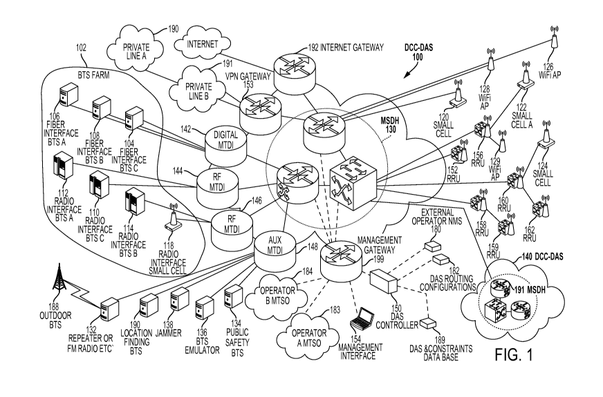
Figure 1 depicts a function block diagram of DCC-DAS 100 according to an
exemplary embodiment of the invention. DCC-DAS 100 integrates multiple
resources of capacity, such as Cellular 2G/3G/4G resources, public safety
resources,
small cell, and broadband resources into one integrated operational system
that is able
to centrally manage its capacity resources and distribute them accordingly.
BTS farm 102 is the main resource of capacity of DCC-DAS 100. BTS farm
102 comprises various BTS's covering multiple technologies. Digital Fiber
interface
BTS's 104, 106, and 108 have digital baseband fiber interface (For example
CPRI
data) outputs whereas Radio Interface BTS's 110, 112, 114 and radio interface
small
cell 118 have Radio RF outputs.
Other capacity resources, like small cells 118, 120, 122, and 124 or Wi-Fi
access points 126, 128 and 129 can be used by DCC-DAS 100 for offloading
capacity
purposes. They can be installed either in BTS farm 102, like small cell 118,
or in
remote zones, like small cells 120, 122, and 124 and WIFI access points 126,
128,
and 129. MSDH 130 manages all the capacity resources of DCC-DAS 100. DCC-
DAS 100 can be leveraged to manage auxiliary resources like off-air repeaters
(Off
air repeater receives the signal from remote BTS 188) or FM Radios 132, public
safety BTS 134, and BTS emulator 136 for location finding purposes.
DCC-DAS 100 can be used to direct the signal from jammer 138 to specific zones
in
which cellular calls are prohibited. As depicted in Figure 1, DCC-DAS 100 is
modular and can be connected to slave MSDH 191 and / or slave DCC-DAS 140
which covers other zones not serviced by DCC-DAS 100.
Each BTS in BTS farm 102 is connected to an MTDI. As shown, Digital fiber
interfaced BTS's 104, 106, and 108 are connected to digital MTDI 142; RF BTS's
110 and 112 are connected to RF MTDI 144; and RF BTS 114 and Small Cell 118
are connected to RF MTDI 146. RF MTDIs 144 and 146 may passively combine the
incoming RF signals from the various RF BTS's (110, 112, 114, and,118 ) and
adjust
the level of the RF signals to the working level required by MTDI digital
processor
(320 in Figure 3 ) which is part of each MTDI. Each MTDI can handle multiple
BTS's. However if the number of BTS's in BTS farm 102 is greater than the
maximum that can be handled by a single MTDI, then a number of additional MTDP
s
may be deployed as depicted in Figure 1. Each BTS may also have MIMO links.
The
4
CA 02961696 2017-03-16
WO 2016/049002 PCT/US2015/051412
MIMO link connections and the way DCC -DAS 100 deals with MIMO links is
shown separately in Figure 15.
Figure 1 depicts multiple RRUs 152, 156, 160, 162 which are connected to
MSDH 130. Each RRU with its own antenna system covers a specific zone.
DCC-DAS 100 serves as IP backhaul for various devices such as Wi-Fi
Access Points 128 and 129 or small cells 120 and 122.They can be directly
connected to MSDH 130 like Wi-Fi access point (AP) 126 and Small cell 120 or
through the RRUs like small cell 122 and Wi-Fi AP 129.
The IP backhaul data aforementioned is routed to MSDH 130 who splits the IP
backhaul data from the digitized cellular data and sends the IP data to the
Internet
gateway 192 or VPN gateway 153 from which it is routed to the internet or to
private
lines 190 and 191, thus connecting those Wi-Fi APs or small cells with the
external
world or the operators network.
DAS controller 150 manages and controls the DCC-DAS 100. DAS controller
140 stores the various configurations of the DAS and various parameters such
as
routing configurations 182 (which is part of DAS controller 150) and
Infrastructure
constraints database 189 which is also part of DAS controller 150 . DAS
controller
150 interfaces with MSDH 130 through management gateway 199. The human
machine interface 154 which enables the DAS operator to control and manage the
system is also interfaced with the MSDH 130 through management gateway 199.
DAS controller 150 is able to connect to an external operator NMS (Network
Management System) , send alarm data, or accept control data from the NMS.
This
NMS can be a conventional NMS or part of a Cloud computing network that
supports
multiple BTSs. The management gateway 199 can directly interface with the
operators' mobile telephone switching office (MTSO) 183, 184 for various
control
and management functions which will be explained later or it can interface
with the
operator cloud computing network
In the downlink direction, each MTDI converts each incoming RF signal to an
IF signal and then digitizes the IF signals and passes them through a digital
filter
bank. The MTDI may filter each incoming signal using a specific digital filter
matched to the technology and the bandwidth of each BTS cell resource as shown
in
Figure 2A. A cell resource is defined as a contiguous piece of spectrum that
the
operator of the DCC-DAS wishes to distribute, for example, consisting of one
or more
wireless signals of the same wireless cellular technology type. However, this
is just
5
CA 02961696 2017-03-16
WO 2016/049002 PCT/US2015/051412
an example. A cell resource can also be any contiguous piece of spectrum in
the
frequency bands of the DCC-DAS that the operator wishes to digitize and
distribute
via the DCC-DAS RRUs. Figure 2A shows as an example the cell resources in the
US PCS frequency band. Al and A2 are VerizonTM cell resources in the PCS band;
Bl, B2, and B3 are AT&TTm cell resources in the PCS band; and Cl, C2, and C3
are
SprintTM cell resources in the PCS band. The MTDI then converts the digital
filtered
signals to a digital stream of data samples (e.g. I/Q data samples) which are
routed to
MSDH 130. Fig 2A depicts also the digital filters that are assigned to each
cell
resource.
Figure 2B shows a conceptual representation of the data flow in the digital
link 210 between the MSDH 130 and the RRU 156. It clearly shows the cell
resource
data (203), Cl, Al, C2, B 1, A2 which are components of the digital links
between
the two modules. It also shows the Ethernet backhaul data packets 205 for the
small
Cell 122 and Wi-Fi AP 129 marked as ABCA etc. ,as well as Ethernet packets
(201)
for management and internet (200) purposes.
In the uplink direction, each MTDI performs the reverse operation. The
MTDI receives a digital stream of data samples representing the cellular
uplink
channels coming from the Remote Radio Units (RRUs) through MSDH 130. It
combines signals destined for the same BTS input and converts them to uplink
signals
that are sent to the various BTS's. In the uplink each MTDI may have the same
structure of cell resources and digital filters associated with them which is
a mirror
image of the Downlink cell resources and digital filters just shifted in
frequency to the
uplink channels of each BTS All this as depicted in Fig2C
There are, for example, three functionally different MTDI modules: digital
MTDIs that connect to BTS's through a digital interface such as digital fiber;
RF
MTDIs that interface using analogue RF signals with RF BTS's; and auxiliary
BTS's
that interface with auxiliary equipment. But the structure of cell resources
and digital
filters associated with them prevails in all the three MTDI modules
MSDH 130 is the central hub of DCC-DAS 100. MSDH 130 receives the
digital streams of cell resource data from the MTDP s and routes them to the
various
RRUs as directed by DAS controller 150. In the uplink direction, MSDH 130
performs the reverse operation. MSDH 130 receives data from the RRUs and
directs
it to the relevant MTDI which is then sent to the relevant BTS. Where the same
cell
resource is allocated to more than one RRU, the uplink signals from the RRUs
are
6
CA 02961696 2017-03-16
WO 2016/049002 PCT/US2015/051412
summed together in order to create a single combined uplink signal for that
cell
resource which is then sent to the MTDI.
As aforementioned, the MSDH 130 also handles Ethernet data which is used
as the IP backhaul of the small cells (120, 122, and 124) and Wi-Fi APs (126,
128,
and 129) and routes the data to Internet gateway 192 or VPN gateway 153.
Each RRU 156, 158, 160, and 162 is basically a multiple band, multiple
technology digital repeater which receives a digital stream of cell resource
data
(digitized signals) from the MSDH 130, converts the data from IF signals to RF
signals, and transmits the RF signals to one or more zones in the downlink
direction.
A zone is a geographical area covered by a single RRU output. Since an RRU may
be
connected to one or more antennas, a zone may be the area covered by one or
more
antennas which are all connected to the RRU. In the uplink direction, the RRU
performs the reverse operation. The RRU receives RF signals, converts them to
IF
signals, digitizes the IF signal, passes the digitized IF signal through a
digital filter
bank consisting of the array of uplink cell resources and digital filters
associated with
them, and sends the resulting signal to MSDH 130.
DCC-DAS controller 150, together with the database routing module 182 and
control and management interface 154, store and control the various
configurations of
DCC-DAS 100.Data base 189 may also store all the cell resources measurements
as
well as interferences measurements performed in each digital filter (Fig 2 C
and 2 A)
during the commissioning of the DCC-DAS
Figure 3 depicts an exemplary MTDI 300 designed to cover all the European
spectrum consisting of four frequency bands, namely 900/1800/2100/2600 MHZ. As
shown in Figure 3, MTDI 300 comprises four downlink (DL) modules 302, 304,
306,
and 308 (one module for each frequency band) and four uplink (UL) modules 310,
312, 314, and 316. Each DL module (consisting of LNA 3021, RF to IF Down
conversion module 3022, and A/D converter 3023) converts the whole frequency
band (e.g., the whole 900 MHz European band covering 35 MHz, the whole DCS
band covering 75 MHz, or the whole US PCS band covering 65 MHz) into IF and
then digitizes all the incoming signals in this band. As an example, downlink
module
306 converts all the UMTS band to IF and digitizes it. The digitized data
coming
from the four DL modules enters a digital processor 320 comprising the digital
filter
bank 318 which allocates a digital filter to each cell resource. Such a
digital filter
bank together with the associated digital filters of the PCS band for example
is
7
CA 02961696 2017-03-16
WO 2016/049002 PCT/US2015/051412
depicted in Fig 2A for the downlink path and 2C for the uplink path .Thus,
each cell
resource has its own digital filter. Digital filter bank 318 may consist for
example of
16 different filters. However, any number of different filters may be
utilized. A
digital filter is defined as a selective function that is intended to pass
signals for one
cell resource as previously defined. Each digital filter may have its own
separate and
distinct transfer function consisting of a specific filter mask as required
for example
by the specific technology standards, specific bandwidth, slopes, gain etc.
The digital
filters may all be implemented by a single digital filter bank 318 or may be
distributed
across a number of different processing modules. The digital filters in
digital filter
bank 318 may be operable in both the uplink and downlink directions. The
digitized
RF data contained in each digital filter (in each RRU or each MTDI ) which
consists
of digital downlink or uplink cell resources +noise +any interference may be
monitored and stored in the DCC-DAS data base (Fig 1- 189) through any
operational or commissioning phase of the system
The MTDI Digital processor 320 is programmed to convert the output of the
digital filter bank 318 into a serial stream of digitized Cell Resource I/Q
data (each
such cell resource I/Q data is a digital baseband representation of the RF
signal in the
digital filter covering the frequency band of one cell resource. In other
words, each
such cell resource I/Q data is the digitized representation of the RF signal
of a specific
cell resource (which would typically be a baseband representation) which is
obtained
from the output of digital filter bank 318 and sent to MSDH 130 through
transceiver
330. In the uplink the reverse operation is performed by the uplink modules
310,
312,314, 316, each one consisting of 3101,3102,3103.
Figure 4 depicts an analog representation 401 of the stream of serial Cell
resource data which is the output of digital filter bank 318. The output of
digital filter
bank 318 constitutes all the cell resources of the BTS farm 102 in one sector.
A sector
cellular resource vector is defined as
Si(C1 .............. Cn )
where Si is the sector no. i and Cl...Cn are the cellular resources (cell
resources )1 to n allocated to that specific sector. The analog representation
in Figure
4 demonstrates a case where n=16 ,and there are 4 bands and 4 cell resources
per band
and that each cell resource which is an analog representation of the output of
a digital
filter may have its own separate and distinct transfer function.
8
CA 02961696 2017-03-16
WO 2016/049002 PCT/US2015/051412
Zone sector Allocation - Figure 5A depicts a stream of data 500 comprising
sixteen baseband cell resource data samples 502 Cl... .C16 with header 504 and
Cyclic Redundancy Check (CRC) 506. Header 504 and CRC 506 identify data stream
500 formed by one sampling of all the 16 filters in all the frequency bands
and
constitutes all the capacity resources of one sector assigned to one MTDI. In
this case
the whole vector S(C1....C16) which comprises all the cell resources of one
sector
will be allocated as one unit to a number of zones . This is called Zone
sector
allocation.
Cell Resource Allocation - Figure 5B depicts an alternative architecture for
forming data packets in which data samples 502 are individually encapsulated
by a
header 504 and a CRC 506. This architecture enables also to independently
identify
each digitized Cell Resource I/Q data which is the output of each filter in
filter bank
318. In this mode of operation, each cell resource is an independent unit and
can be
routed separately to different zones in the building. Instead of routing
complete
sectors, MSDH 130 now routes individual cell resources to the various zones.
Thus,
each cell resource data which is the output of each digital filter in digital
filter bank
318 can now be routed to different zones. Additionally, the gain and power
level of
each cell resource can be individually adjusted. This mode may also be
referred to as
zone cell resource allocation, compared to zone sector allocation depicted in
Figure
5A
The aforementioned data format is only an example. Header 504 may be
omitted if the identity of data samples 502 can be identified by some other
means (e.g.
implicitly due to prior negotiation over a management interface or due to some
overall
frame structure) and CRC 506 may be omitted in the case that error detection
is
performed by some other means or is not of interest.
It should be obvious to one skilled in the art that the sixteen filters in
digital
filter bank 318 or the four European frequency bands or the number of BTS's
are just
an example. All these parameters can vary based on the needs of the system
designer.
The size of digital filter bank 318 depends on the processing capacity of the
MTDI
and a more powerful processor will enable a bigger filter bank covering more
filters
and more cell resources.
The above described process is an efficient way to multiplex multiple outputs
of many BTS's and various technologies into one serial stream of digital Cell
resource
I/Q data samples using one module and one processor with one digital filter
bank
9
CA 02961696 2017-03-16
WO 2016/049002 PCT/US2015/051412
where each data sample represents one cell resource and where the signal
carried by
that stream of data samples is processed according to its own specific
transfer
function. The group of data samples coming from one filter bank typically
constitutes
all the cell resources of one sector. The digital stream of Cell Resource I/Q
data
samples can use OBSAI/CPRI protocol or may use any other specific protocol
chosen
by the designer. In the example shown in Figure 3, MTDI 300 consisting of one
digital filter bank 318 can cover all the 4 European cellular bands (GSM
900,DCS
1800,UMTS 2100 and LTE2600 ) and can integrate 16 BTS's, each one having its
own cell resource. Further, MTDI 300 can cover various cell resources in one
band
each one having different technology or same technology with different
transfer
function (frequency response).
An alternative implementation, which is functionally equivalent, is to
implement filter bank 318 and the division of the signals into cell resource
I/Q data
samples on the MSDH 130. In this case, MTDI 300 would transmit a digitized
representation of the whole of each frequency band to be divided into cell
resource
I/Q data samples internally within MSDH 130. MTDI 300 functionality described
here would, in such a case, be distributed between MTDI 300 and MSDH 130.If
the
MTDI is to perform cell resource and noise and interference measurements in
this
case it would be done for the whole frequency band (like UMTS 2100 MHZ or PCS
1900 MHZ for example) and cover multiple RF cell resources and multiple
interferences.
The use of digital filter bank 318 allows the amount of data flowing through
DCC-DAS 100 to be reduced, thus enabling more capacity in the cables. This is
due
to the fact that only the output of digital filter bank 318 (or just the cell
resources
data) is converted to serial data and not the whole spectral bandwidth of each
specific
band. The saving in the data quantity becomes significant, particularly when
only one
or two operators are involved and their assigned frequencies are just part of
the whole
spectral width of the frequency band. Formatting of the digital data for
transmission
through DCC-DAS 100 may also include an additional compression stage to even
further reduce the data flowing in the CPRI links.
In the near future, the European and America cellular operators will be
deploying new technologies in legacy bands. For example, the 900MHZ GSM band
in Europe is being reallocated to allow multiple technologies in this band so
that now
it becomes 900MHZ covering GSM /LTE/WCDMA. The same is happening to other
CA 02961696 2017-03-16
WO 2016/049002 PCT/US2015/051412
bands worldwide. The DCC-DAS architecture enables the user to easily
reallocate or
re-farm the spectrum in each band according to the various technologies
deployed in
this band. All he has to do is reconfigure the filter bank and select specific
digital
filter characteristics with specific transfer functions desired for each
digital filter to
accommodate to the new technologies cell resources. Such reconfiguration can
be
done via management interface 154 which may be accessed locally or from a
remote
location though the intern& or off-air through RF modems
Further, it is easy to add additional BTS's to BTS farm 102. All a user must
do is connect the new BTS to the system and allocate specific filters in
digital filter
bank 318 to the new cell resources associated with the new BTS. If the BTS
contains
two or more technologies or non-contiguous cell resources, then two or more
digital
filters should be allocated in the digital filter bank, with each one of the
digital filters
allocated to one cell resource
In the uplink direction, MTDI 300 performs the reverse operation. MTDI 300
receives the stream of data packets coming from the various RRUs through MSDH
130 and distributes them throughout BTS farm 102. The RRU's have their own
digital filter bank accordingly.
Each MTDI 300 may serve one sector and the output of MTDI 300 will be
routed by MSDH 130 to one or more zones. If additional zones need to be
covered,
or more capacity is required in a geographical region, then a new sector may
be used
to cover the additional zones in the building, or to provide more capacity to
existing
zones by dividing the area covered by DCC-DAS into new zones, each one covered
by a dedicated sector. In this case, a second MTDI (MTDI 146 in Figure 1)may
be
connected to an additional BTS 114, and small cell 118 for example. The output
of
the second MTDI 146 will be connected to MSDH 130. This second MTDI output
will be another cell resource vector consisting of all the cell resources in
the second
sector. DCC-DAS 100 can now support up to n different sectors. Each sector
will be
routed to one or more zones in the area covered by DCC-DAS 100.
Figure 6, depicts a block diagram of MSDH 130. MSDH 130 is the central
hub of the DCC-DAS 100. MSDH 130 connects to all the elements of DCC-DAS 100
like the RRU's (156, 158, 160, and 162); BTS farm 102 through MTDIs 142, 144,
146, and 148; Wi-Fi access points 126, 128, and 129; small cells 118, 120,
122, and
124; and slave DCC-DAS 140 for cascading purposes.
11
CA 02961696 2017-03-16
WO 2016/049002 PCT/US2015/051412
The main function of MSDH 130 is to distribute and route the downlink
signals coming from the MTDI(s) to the various RRUs as directed by the DCC-DAS
Controller 150 and perform the reverse operation to combine the uplink
signals. All
this is done based on the distribution matrix programmed into the I/Q data
switch and
combiner 600 Figure 6 which is dynamically controlled by management processor
602.
MSDH 130 connects through various plug-in transceivers 604 to the RRUs
which are located at various zones in the area covered by DCC-DAS 100, and
through
plug-in transceivers 608 to the MTDIs, and optionally slave MSDHs in case the
DCC-
DAS 100 is extended with multiple MSDHs. The exact number, configuration, and
capacity depend on the building or campus size which is being served by DCC-
DAS
100. Plug-in transceivers 608 and 604 transfer cell resource data samples from
the
MTDIs or slave MSDHs to and from the relevant RRUs based on the MSDH
distribution matrix in I/Q data switch and combiner 600. The communication can
be
based on any suitable digital protocol, such as CPRI/OBSAI serial protocols or
any
other serial data protocol. MSDH 130 also embeds an Ethernet layer with the
serial
data stream of digitized cell resource data samples in order to transmit
control data
and serve as the IP backhaul of the offload devices such as small cells, Wi-Fi
access
points, or any other offload device. The various offload devices may be
connected to
the RRUs (e.g., Wi-Fi AP 129 is connected to RRU 156 by Ethernet connection in
Figure 1) and from there through the RRU CPRI link to the MSDH 130 or directly
to
the Ethernet switch 612 associated with the MSDH (e.g., Wi-Fi AP 128 in Figure
1).
Data link blocks 606 in Figure 6 are responsible for formatting the data
transmitted over the digital links. In the example, interfaces are provided
for data
streams of 16 downlink cell resource data samples (CRD 1...CRD 16) and the
corresponding 16 uplink cell resource data samples. In addition, data link
block 606
provides an interface for Ethernet data packets that serves as the IP backhaul
for the
offload devices, and a CPU interface (CPU IF) for control and management of
the
data link. These data elements are then formatted according to the protocol
mapping
layer for transmission / reception over the physical layer. The data link
blocks 606
incorporate a delay management function which allows the round-trip delay
across
each interconnection to be measured. This can be used to equalize delays
through the
DCC-DAS 100.
12
CA 02961696 2017-03-16
WO 2016/049002 PCT/US2015/051412
MSDH 130 connects through one or more transceivers 608 in Figure 6 to the
various MTDIs and slave MSDHs. Typically, one transceiver 608 connects to each
MTDI or slave MSDH; several transceivers may be used in parallel if the total
data
bandwidth exceeds the capacity of a single transceiver. The I/Q data switch
and
combiner 600 is enabled to combine (sum together) uplink cell resource data
samples
destined to a transceiver 608. This function is not necessary for transceiver
604 which
connects to an RRU; omitting the function simplifies the design of I/Q data
switch
and combiner 600. The transceiver 604 therefore only requires a sub-set of the
functionality of transceiver 608. A different implementation of the MSDH could
allow combining of samples at all outputs, in which case any transceiver could
function either as a transceiver 608 and 604 as required. Also, an operator
may
choose to use a transceiver that is capable as operating as a transceiver 608
as a
transceiver 604 to increase the number of supported RRUs.
The Ethernet layer for each connection is combined by an Ethernet switch
612, which may be integrated within the MSDH 130 or may be a stand-alone
device
external to MSDH 130. From there, the Ethernet data is connected to auxiliary
equipment such as internet gateway 192, DCC-DAS controller 150, management
interface154, etc. as shown in Figure 1.
MSDH management processor 602 is responsible for maintaining the
operating state of the MSDH 130 through the local bus controller. It is
connected to
the Ethernet switch 612 which enables remote access from the internet gateway
192.
It may also communicate with peer devices (MTDIs, RRUs or MSDHs) as part of
establishing and updating the connections through data link blocks 606. This
communication may take place via Ethernet switch 612, or may involve some
lower
level communication directly via data link blocks 606.
Gain and routing management function 610 is responsible for updating the
MSDH distribution matrix implemented by I/Q data switch and combiner 600 under
control of the MSDH management processor 602.
Clock distribution function 614 provides the reference clock used through the
MSDH 130. An MSDH can be the master of the system timing, or it can be a slave
to
a peer MSDH. In the event that it is master of the system timing, it generates
its own
internal reference clock using an in-built oscillator such as a TCXO, or it
may receive
an external reference clock from the external timing reference connection. In
the
event that the MSDH is slave to another MSDH it receives its timing reference
via the
13
CA 02961696 2017-03-16
WO 2016/049002 PCT/US2015/051412
corresponding transceiver 608. This timing reference is fed to the jitter
cleaner to
generate the internal timing reference used for all other transceivers 604 or
608. This
clock distribution system ensures that transfer is synchronous across all data
links,
and avoids the need for resampling / retiming where data is interchanged
between
devices.
MSDH 130 connects through one or more transceivers 608 to auxiliary MTDI
148 (Figure 1) which interfaces with auxiliary equipment such as repeaters or
FM
radio 132, jammer 138, public safety BTS 134, and location finding BTS 190.
MSDH 130 connects to slave MSDH 191 - Figure 1 - through one of the
transceivers 608, thus enabling a modular growth of the system. Several slave
MSDH 's which control additional multiple RRUs can be cascaded using this
methodology, enabling the system to cover huge campuses and residential areas.
Thus, this architecture enables modular growth by cascading MSDH elements,
each
one of them serving multiple remote RRUs.
Returning now to Figure 6, one can see how Ethernet data is switched from
transceiver 604, through Ethernet switch 612 to internet gateway 192. The
backhaul
IP data is in this way transmitted directly to the internet instead of to the
MTDI like in
the case of the cell resource data samples.
Remote Radio Units 152,156, 158, 159, 160, and 162 are the transmitting and
receiving front ends of the system. Each RRU is a multiband digital repeater
which
can be designed to cover all wireless or cellular technologies of interest (US
or
European or any other). Figure 7 depicts a block diagram of an exemplary RRU
700.
In the downlink path, transceiver 702 receives the serial stream of cell
resource data
samples from MSDH 130 (CRD1...CRD16 in 606 Figure 6). RRU 700 then processes
and passes the signal through the digital processor 704. Digital processor 704
has a
similar, though not necessarily identical, digital filter bank to MTDI 300,
but in the
uplink path. This digital filter bank in the RRU contains one or more relevant
digital
filters corresponding to the cell resources which are allocated to the RRU
700.
Digital processor 704 reconstructs the composite signal for each output
frequency
band from the cell resource data samples, and outputs each signal to the
corresponding band module 730. D/A converter 706 in each band module 730
converts the outputs of the filter bank relevant to this band to an analog IF
signal
which is then up-converted to RF frequency by converter 708. Downlink
amplifier
14
CA 02961696 2017-03-16
WO 2016/049002 PCT/US2015/051412
710 amplifies the signal and sends it to multiplexer 712. Multiplexer 712
combines
all the N relevant bands into the required number of RF output signals.
The output of multiplexer 712 is connected to one or more outputs covering
one zone. The output may be split into one or more antennas, each one covering
a
sub-zone which may consist of one room or one floor or group of floors in the
building (or relevant users areas in an outdoor environment). In the uplink
path
multiplexer 712 receives all the mobile cell-phone signals and splits them to
all the
relevant N bands. For each band, a low noise amplified (LNA) 714 provides low
noise amplification. The amplified signal is then down converted to IF by down
converter 716 and then converted from analog to digital by AID converter 718.
Digital processor 704 combines all the signals from all the bands and passes
the
uplink digital signals through a digital filter bank consisting of the array
of uplink
digital filters associated with all the uplink cell resources The cell
resource s signals
are then converted to serial uplink cell resource data samples and sent
through the
transceiver 702 to MSDH 130. As in the case of the MTDI, it is possible to
partition
the system such that the filter bank is implemented on MSDH 130 while
maintaining
the same functionality.
RRU 700 additionally contains a sniffer receiver circuit in each band module
130 which comprises circulator 720, LNA 722, and frequency shift module 724.
The
purpose of the sniffer receiver is to measure all the downlink signals coming
from the
adjacent RRUs and the macro network in order to measure the isolation between
the
various RRUs and the level of penetration of the macro network into the
building, or
to be more precise into the zone covered by the one or more antennas connected
to
each RRU 700. The process of measuring the isolation between the various RRUs
is
done by shutting down or disconnecting the output of DL amplifier 710 only in
the
measuring RRU from the multiplexer 712 and disconnecting the output of LNA 714
in the UL path from down converter 716,and connecting UL RF/IF down converter
716 to Freq. shift 724 of the measuring RRU. The receiving path of the
measuring
RRU consists now of multiplexer 712 ,circulator 720,LNA 722,Frequency shifter
724
and down converter 716. This measuring RRU is practically acting now as a
sniffer
receiver. The rest of the relevant RRUs in the DAS are transmitting test
signals
simultaneously (or in succession) in all the cell resources frequency
allocations, or
alternatively are transmitting normal DL traffic and logging the power level
etc. of the
transmitted signals. These test signals are then received in the downlink path
of the
CA 02961696 2017-03-16
WO 2016/049002 PCT/US2015/051412
specific measuring RRU 700 who is in a sniffing receiving mode through the
aforesaid sniffer receiver circuit which comprises circulator 720, LNA 722,
and
frequency shift module 724 and RF/IF down converter. The downlink test
signals,
which are received by multiplexer 712 are diverted by circulator 720 to LNA
722 and
amplified by LNA 722, are now converted by frequency shift module 724 to the
relevant up link frequencies and are now processed by the uplink path as if
they were
uplink signals. One should remember that these signals are an image of the
original
downlink signals penetrating this RRU which are shifted by a certain constant
to the
uplink channels. For example, the downlink signals in the US cellular band are
shifted by 45 MHZ from downlink to uplink signals. The shifted signal is then
processed by the uplink channels. The level of the test signal is measured and
sent to
MSDH 130 for processing. Based on the received signal levels in each cell
resource
filter in the filter bank located in digital processor 704 and the level of
the test signals
(either generated test signals or logged downlink traffic), MSDH 130 can
calculate the
isolation between each RRU and the specific measuring RRU and also the level
of
penetration of the macro network to that specific measuring RRU zone.
Different implementations of the sniffer receiver circuit can be considered,
which achieve the same outcome while providing various trade-offs. For
example, the
LNA 722 may be omitted at the expense of reduced sensitivity. The frequency
shift
function may be omitted in case the downlink frequency band lies within the
tunable
range of uplink RF/IF down converter 716.
As aforesaid, the sniffer receiver circuit may be used to measure the
penetration of the macro network into the building. In this process, all the
DCC-
DAS's RRUs downlink and uplink channels are muted or disconnected as
aforementioned and all the RRU's are now receiving signals through the
sniffers
receiver which consist of elements 712, 720, 722, 724, 716, 718, and 704 .
Thus, the
RRU sniffer receiver may receive now only the external macro network signals
which
may penetrate the building. By measuring the signal strength in each filter of
the
uplink digital filter bank in digital processor 704, the system may measure
the macro
network signals in each of the cell resources frequencies (el ...cn ). A
vector MSj
(C1..Cn) may now be generated. DCC-DAS controller 150 may now know how
much interference the macro network causes to DCC-DAS 100 and also one skilled
in
the art knows that this is related to the level of interference DCC-DAS 100
may be
causing to the macro-network by signals leaking from the building. All this
16
CA 02961696 2017-03-16
WO 2016/049002
PCT/US2015/051412
information is critical to the performance of DCC-DAS 100 and the Macro-
network
as well. DCC-DAS 100 is thus capable of calculating this information without
the use
of external test equipment and costly manpower.
RRU 700 may comprise one or more transceiver ports 726 which connect
RRU 700 to a slave RRU. The slave RRU can be used for extending the coverage
of
RRU 700 to additional zones (i.e. floors for example); to add more bands or
technologies to the master RRU; or to provide MIMO capabilities to the bands
in
RRU 700. Typical interfaces, such as OBSAI / CPRI over a fiber-optic
connection,
may be used to connect to the slave RRU. This configuration allows for
connecting
multiple RRUs in cascade all being connected through one transceiver 702 and
one
cable to MSDH 130.
Additional Ethernet port 728 may also connect to an offload device such as
Wi-Fi Access Point 129 or Small Cell 124 (see Figure 1). In this case,
Ethernet port
728 serves as the IP Backhaul link for the offload devices. The backhaul data
is
connected through Ethernet port 728 to digital processor 704 and from there
through
transceiver 702 to MSDH 130. The MSDH 130 splits the cell resource data from
the
IP backhaul data or other Ethernet-carried data as aforementioned. This method
enables a quick and easy integration of DCC-DAS 100 with any device that
requires
IP backhaul infrastructure.
The communication from MSDH 130 to other DCC-DAS 100 modules in
most cases may be based on fiber optic cables (Single Mode and/or Multi Mode
Fiber) and associated transceivers in order to enable high capacity traffic.
However,
DCC-DAS 100 may use any cable that exists in the building such as CAT5 cables,
copper cables, Ethernet cables, TV cables, coaxial cables, etc. In order
achieve this
flexibility, the transceivers may not be an integral part of the MSDH, RRU, or
even
the MTDI. They can rather be plug-in modules that can be selected based on the
specific installation needs.
All a user has to do is choose the right plug-in transceiver that fits the
cable
and the capacity enabled by that specific cable which was selected. The user
must
then connect it to the cable and plug it into MSDH 130. If the installation is
changed
and new cables are installed then the plug in transceivers can be replaced
accordingly.
DCC-DAS management processor 602 (Figure 6) is programmed to read
(from the system configuration or the transceivers themselves) the maximum
capacity
that each transceiver/cable can handle and will not allocate any capacity
which is
17
CA 02961696 2017-03-16
WO 2016/049002 PCT/US2015/051412
higher than the maximum supported by that specific transceiver and the
associated
cable
The algorithm for mapping and handling PIM and other uplink interferences
consists of three phases. The first phase maps interferences when no downlink
channel is active. The second and third phases map the PIM and other uplink
interferences which may be caused by the active downlink channel.
Phase A ¨ Measuring and mapping any excessive noise and interference in the
uplink channels when all the DAS downlink channels are shut off or muted
The purpose of phase A is to measure the excessive noise and interferences
that may be generated in the Uplink channels of the DCC-DAS due to external
sources or wrong calibration of the uplink channels and identify any
calibration or
interference issue. By excessive noise, we mean any noise level that is higher
than
the noise levels which are designed to be in the various DCC-DAS uplink
channels in
the design phase. The mapping is performed on one or more of the cell
resources, on
one or more of the RRUs, and may be performed in one or more test points
between
the antenna and the interface to the BTSs along the uplink receive path. The
MTDI
test as described below serves as such an example.
Phase B ¨ Measuring and mapping any excessive noise and interference in the
uplink channels when all the DAS downlink channels are active
Phase B is performed by activating one or more BTSs in zero traffic mode (no
uplink calls) in full transmission power (or activate one more synthesizers
which may
simulate downlink transmission) with no uplink activity, and measure and map
any
excessive noise or interference in the uplink cell resources digital filters,
which may
be generated due to downlink transmissions such as PIM signals,
intermodulation
products, reflections from external sources, or any other sources. The mapping
is
performed on one or more of the cell resources, on one or more of the RRUs,
and may
be performed in one or more test points between the antenna and the interface
to the
BTSs along the uplink receive path.
Phase C ¨ Activate one or more BTSs with uplink activity
Phase C is performed by activating one or more BTSs in full operational mode
in with operational uplink activity and measuring and mapping any excessive
noise or
18
CA 02961696 2017-03-16
WO 2016/049002 PCT/US2015/051412
interference in the uplink cell resources digital filters, which may be
generated due to
any reason. The mapping is performed on one or more of the cell resources, on
one or
more of the RRUs, and may be performed in one or more test points between the
antenna and the interface to the BTSs along the uplink receive path. Unlike
phases A
and B, which are intended to be done in commissioning and or maintenance
phases in
which the DAS is partially or fully nonoperational, phase C may be performed
when
the DAS is operational.
Figure 8 depicts a flowchart for performing phase A described above. This
phase consists of measuring and recording noise levels and interferences in
all the
uplink cell resources digital filters in the digital filter bank (part of
Digital processor
704 in Fig. 7) in one or more frequency bands and one or more RRUs. This is
done
when all the downlink channels are disconnected, switched off, or muted. It is
performed sequentially on each RRU and may consist of the following steps with
reference to Figure 8:
Step 8001 - ascertain that all the relevant DCC-DAS RRUs downlink channels
are switched off, muted, or disconnected.
Step 8002 - perform measurements of signal data in one or more of the uplink
cell resources digital filters (Figure 2C) in a first RRU digital filter bank
(part of 704
Figure 7). This step may be performed by the DAS controller 150 (Figure 1)
which
may activate the digital processor (704 Figure 7) in the one or more RRUs. The
digital
processor 704 may perform measurements of the data in each digital filter.
This data
may be recorded in the DCC-DAS database 189 (Figure 1).
Steps 8003-8005 - The digital processor 704 may also perform an FFT (fast
Fourier transform) algorithm on the data in one or more digital filters in the
digital
filter bank in one or more RRUs. There may be some digital filters in an RRU
in
which there are external interferences which may prevent the system from
proper
noise level measurement. The FFT process, which is performed on the signal
measurements in one or more digital filters, may identify the exact parameters
of this
interference such as interference level, central frequency, bandwidth, etc.
(step 8004).
A report may be sent (step 8005) by the digital processor (704 in Figure 7) to
the DAS
controller 150 (Figure 1) with all the interferences data which was identified
in the
one or more digital filters in 704. The DAS controller 150 may store this
interference
data in the DAS database 189 (Figure 1) and also may send a report to the
system
19
CA 02961696 2017-03-16
WO 2016/049002 PCT/US2015/051412
integrator with this data. The system integrator may try to solve all the
interferences
issues.
Step 8006 - Once this is done and all the interferences are eliminated or at
least identified, the process may be repeated and the digital processors may
perform
noise measurement in one or more uplink digital filters of an RRU. All this
data,
including interferences signals which were not resolved, is recorded and sent
to the
DCC-DAS database 189.
Steps 8007 and 8008 - The DAS controller 150 (Figure 1) may compare the
noise level measured in step 8006 to the desired design values for each cell
resource
filter. The system then sends a report with all the noise levels measured in
the one or
more uplink cell resource digital filters in the RRU. If the noise levels are
higher or
significantly lower than the desired design values, the DAS controller 150 may
submit
an alarm with a report delineating the malfunctioning cell resource digital
filters. Such
an alarm will also consist of a report delineating the RRU number, the
specific bands
in which there is a problem, and the specific cell resource filters in which
there is a
problem. If, however, the noise level measured in all the cell resource
filters are
within the range of the desired parameters for all the RRUs, it means that the
system
is well calibrated and the process proceeds to step 8009 (step 6).
Step 8009 - The same procedure of interference and noise level measurements
and mapping as depicted in Steps 8002-8008 are repeated and recorded for more
or all
RRUs in one or more or all their cell resource digital filters in one or more
or all
frequency bands. The purpose of this step is to ascertain that there is no any
internal
source of noise or interference in the DCC-DAS cables or modules anywhere
between
the RRUs and the DAS antenna.
Step 8010 - The same procedure of interference and noise level measurements
and mapping as depicted in Steps 8002-8009 may now be repeated and recorded
for
any element in the uplink receive path such as one or more MTDIs (such as 144
or
142 in Figure 1) in one or more of their cell resource digital filters in the
digital filter
bank (318 in Figure 3) in one or more frequency bands (Figure 8 shows an MTDI
as
an example for a test point). The purpose of this step is to ascertain that
there is no
any internal source of excessive noise or interference in the DCC-DAS cables
or
modules anywhere between the RRUs and the interface to the BTSs.
CA 02961696 2017-03-16
WO 2016/049002 PCT/US2015/051412
Step 8011 - By the end of phase A, all the noise levels of each cell resource
digital filter in each band in each MTDI and RRU in the system are recorded
and
stored in the system controller database.
Figure 9 depicts a flowchart showing the steps of Phase B. The activated DAS
downlink channels are all in no traffic mode so that there is no uplink
communication
or activity. Alternatively, one more synthesizers which simulate downlink
transmissions may be used. This phase consists of measuring and recording
noise and
interference levels in one or more or all RRUs when all the downlink channels
are
switched ON. It is performed on one or more or all the RRUs and may consist of
the
following steps:
Step 9001 - Ascertain that one or more or all the DCC-DAS RRUs' downlink
channels are switched ON and one or more or all the BTSs with their cell
resources
are ON. This phase B could be divided into two steps: one when all the BTSs
are ON
but at zero traffic conditions. In this mode, all the downlink channels are ON
but
there are no uplink signals that may interfere with the measurements. This BTS
zero
traffic mode can be used in the commissioning phase. In an operational phase,
when
the BTSs in the DAS head end room are in full traffic mode, there may be
uplink
signals in the building which will interfere with the noise and interference
measurements. In this operational mode, the DCC-DAS system may disable uplink
traffic just in a the specific cell resource in which there are currently
measurements
being performed while all the other cell resources are in full traffic mode.
Thus, there
is minimum disruption to the normal operation of the DCC-DAS.
Step 8002 - perform measurements and recording of signal data in all the
uplink cell resources digital filters (Figure 2C) in a first RRU digital
filter bank (part
of 704 in Figure 7). This step may be performed by the DAS controller 150
(Figure
1) which may activate the digital processor (704 in Figure 7 ) in the RRU. The
digital
processor 704 may perform measurements and recording of the data in one or
more
digital filter. This data may be stored in the DCC-DAS database 189 (Figure
1).
Steps 8003-8006 ¨ the digital processor 704 Figure 7 may also perform an
FFT algorithm on the data in one or more digital filter in the digital filter
bank in one
or more RRUs. The FFT process may now be performed on the signal measurements
in one or more digital filters may identify the exact parameters of each
interference
such as interference level, central frequency, bandwidth, etc. (step 9004). A
report
may be sent (step 9006) by the digital processor (704 in Figure 7) to the DAS
21
CA 02961696 2017-03-16
WO 2016/049002 PCT/US2015/051412
controller 150 (Figure 1) with all the interferences data which was identified
in each
digital filter in 704 Figure 7. The DAS controller 150 may store this
interference data
in the DAS database 189 (Figure 1). The DAS controller 150 may now compare the
FFT data generated in phase A with the FFT data generated in phase B. Any new
interference that is now mapped and identified most likely has been generated
by the
downlink channels in the DCC-DAS RRUs and must have leaked to the uplink
channels (One may opt to repeat this phase A just to ascertain that there are
no any
new non downlink related interferences). The DAS controller 150 may now send a
report to the system integrator. This report depicts all the interferences
caused by the
downlink channels and all their parameters such as central frequency,
bandwidth,
interference level, the specific RRU in which this interference was detected,
the
specific band and specific cell resource digital filter which contains the
interference.
All this information may help the system integrator to identify the source of
the
problem and solve it and saves enormous time and costs which would have
incurred if
the integrator tried to identify the problem in the field without such
reported
measurements
Steps 9007 and 9008 - once all the interferences are dealt with, the DAS
controller 150 (Figure 1) may measure the noise levels in each uplink digital
filter in
the filter bank of the RRU and compare these values with the corresponding
noise
level measurements performed and stored in phase A. Any deviation between the
two measurements is due to excessive noise generated in the downlink channels
and
leaking to the uplink channels. The system controller may now send a report to
the
integrator depicting all the noise measurements done in the RRU in each phase
and
showing the exact deviations between the two measurements together with the
RRU
number, the frequency band and the exact digital filter in which there is
excessive
noise.
Step 9009 - the same procedure of interference and noise level measurements
as depicted in steps 9002-9008 may now be repeated and recorded for one or
more
RRUs in one or more of its uplink cell resource digital filters in one or more
frequency band and reports are sent accordingly.
Step 9010 - the same procedure of interference and noise level measurements
as depicted in blocks 9002-9009 may now be repeated and recorded for one or
more
MTDIs in one or more of its uplink cell resource digital filters in the
digital filter
bank (318 in Figure 3) in one or more or all frequency bands. The purpose of
this
22
CA 02961696 2017-03-16
WO 2016/049002 PCT/US2015/051412
step is to ascertain that there is no any internal source of excessive noise
or
interference in the DCC-DAS cables or modules anywhere between the RRUs and
the
MTDIs. The DAS controller stores the measurements performed in this phase B in
the DAS database 189 (Figure 1). The DAS controller 150 may compare this data
with the same data stored in phase A when the downlink channels were OFF. If
there
is any interference or excessive noise measured now which did not exist in
phase A, it
means that there is an internal source in one of the RRUs or the cables or the
MSDH
(130 in Figure 1) that is generating an interference which is leaking to the
MTDI
uplink digital filters. The DAS controller 150 may now send a report to the
system
integrator depicting the exact MTDI, frequency band, digital filter in which
the
interference exists ,the parameters of the interference such central frequency
,bandwidth ,intensity level etc. The DAS controller 150 may now switch off all
the
downlink channels of the DCC-DAS and switch each RRU in a sequence one at a
time to isolate the problem and identify from each RRU and through each cable
the
interference is leaking. The DAS controller may store that data and send a
report
delineating the exact RRU and cable connection in which the problem
originated.
Step 9011 - by the end of this phases A and B, all the interferences in each
uplink cell resource digital filter in each digital filter bank in each band
in each MTDI
and each RRU in the system whether generated by any external source or by the
DAS
downlink channels are identified, their parameters are measured and the
location in
which the problem originated is also identified. All the aforementioned
information is
stored in the DAS database 189 for future maintenance purposes.
Phase C, unlike phases A and B, which may be performed in non-operational
mode when there is no uplink traffic, this mode may be performed when the BTSs
and the DCC-DAS are fully operational and the measurement and mapping of the
uplink interferences are performed in parallel to the operational uplink
downlink
activity of the DAS BTSs. In this operational mode, the system may disable
uplink
traffic just in the one or more specific cell resources in which there are
currently
measurements being performed while all the other cell resources of the DCC-DAS
are
in full traffic mode. Thus, there is a disruption to the operational activity
of the DCC-
DAS. However, it is confined only to the one or more cell resources which are
being
currently measured and mapped. The DCC-DAS in this mode remains fully
operational in all other cell resources. The steps for Phase C are identical
to those of
Phase B depicted in Figure 9. The only difference is that they are performed
in an
23
CA 02961696 2017-03-16
WO 2016/049002
PCT/US2015/051412
operational phase of the DCC-DAS and the DCC-DAS has full activity in all
other
cell resources in which currently no measurements are performed. One skilled
in the
art may realize that in certain cases and certain types of interferences the
interference
can be identified even in the presence of uplink traffic in the specific
digital filters
whose signals are being measured in which case the uplink traffic of this cell
resource does not have to be inhibited.
Although this algorithm teaches about performing FFT algorithm in order to
separate and identify any uplink interference from the desired signal and
system
noise, one skilled in the art could use any other procedure which helps
separate an
interfering signal from noise and desired signals and thus enables to measure
the
interference parameters.
This application teaches mainly about measuring and mapping uplink
interferences in a DCC-DAS. However, the same methodology and procedures could
be used for an analog DAS. In a case of an analog DAS, a frequency band
receiver
with a variable bandwidth could be added to various modules of the DAS such as
the
RRU or the master hub or the BTS interface unit ,a digital sampling unit and
processor could be added to the receiver and thus this receiver and the
digital unit
could perform the same algorithms as aforementioned.
The aforementioned procedure with its phases A ,B and C could be for
example activated in one or more of the following occasions:
a. in the commissioning phase of the DCC-DAS before the DAS becomes
operational.
b. on a regularly scheduled basis. For example once in a while as may be
decided by the operator. The DAS controller 150 scheduler will initiate this
procedure. As aforementioned the DAS controller may disable (by communicating
with the operator NMS) the traffic only in a specific cell resource in which
current
measurements are made. Thus, all the BTSs cell resources except the one which
is
being measured are ON and the disruption to the users traffic is minimized.
c. event driven ¨ when there is a suspicion that that one or more of the BTS's
uplink channels are malfunctioning.
d. in any other case whether activation is done manually or automatically.
The aforementioned procedure with its phases A ,B and C teaches about
sending a report to the system integrator whenever an interference caused by
the DAS
or by an external source is measured and mapped. (see for example blocks 8005,
24
CA 02961696 2017-03-16
WO 2016/049002
PCT/US2015/051412
8008 in Figure 8 and 9006, 9008 in Figure 9). However in parallel or in lieu
of
sending the report the DAS controller may try to handle or deal with the
problem
independently. For example:
a. the DAS controller 150 could switch off one or more uplink or in the
downlink specific cell resource digital filters in which any kind of
interference was
identified.
b. the DAS controller 150 could switch off one or more bands in one or more
RRUs which are found to be a root cause of uplink interferences.
c. the DAS could attenuate the downlink power of one or more RRUs or cell
resources which are found causing interferences to specific uplink channels.