Note: Descriptions are shown in the official language in which they were submitted.
INCREASING BOREHOLE WALL PERMEABILITY
TO FACILITATE FLUID SAMPLING
BACKGROUND
Subsurface formations contain reservoir fluid which, when sampled and
analyzed,
may provide useful information about the formation. For example, fluid
analysis results can
be used to perform reservoir correlations and simulations and to optimize
wellbore placement
and generate production forecasts. Fluid is typically sampled using a probe
that is extended
from a downhole tool assembly and pressed against a borehole wall. Ideally,
when a probe is
pressed against an area of a formation that is highly permeable, fluid is
pumped out from the
formation and into the probe. Low permeability areas of a formation, however,
make fluid
flow and collection difficult.
SUMMARY
In accordance with a general aspect, there is provided a drill string tool
assembly,
comprising: a punching tool that induces fissures to increase permeability in
a localized
region of a borehole wall; a sensor that detects spatial features of the
fissures; processing
logic, coupled to the sensor and punching tool, that adapts operation of the
punching tool
based on said spatial features; and a fluid sampling probe, coupled to the
processing logic,
that samples fluid from the localized region.
In accordance with another aspect, there is provided a method, comprising:
punching
a formation to create fissures in a localized portion of the formation until
at least one of said
fissures aligns with a fluid sampling probe; sampling formation fluid from the
localized
portion; and storing said formation fluid in a drill string tool assembly.
In accordance with a further aspect, there is provided a method, comprising:
punching
a borehole wall to create fissures in a localized region of a formation;
sensing spatial features
of the localized region; and using the spatial features to adjust a position
of a fluid sampling
probe such that the probe is aligned with the localized region.
BRIEF DESCRIPTION OF THE DRAWINGS
Accordingly, there are disclosed in the accompanying drawings and in the
following
description methods and systems for increasing borehole wall permeability to
facilitate fluid
sampling. In the drawings:
Fig. 1 is a schematic view of an illustrative drilling environment, in
accordance with
embodiments;
1
CA 2961722 2018-08-08
Fig. 2 is a schematic view of an illustrative drill string tool assembly, in
accordance
with embodiments;
Fig. 3A is a flow diagram of an illustrative method for increasing the
permeability of
a borehole wall, in accordance with embodiments;
Figs. 3B-3F are schematic views of an illustrative drill string tool assembly
performing the method of Fig. 3A, in accordance with embodiments;
Fig. 4A is a flow diagram of another illustrative method for increasing the
permeability of a borehole wall, in accordance with embodiments; and
Figs. 4B-4F are schematic views of an illustrative drill string tool assembly
performing the method of Fig. 4A, in accordance with embodiments.
DETAILED DESCRIPTION
The methods and systems disclosed herein entail the use of a punching tool to
punch a target
area of a borehole wall, thereby inducing and/or enhancing fissures throughout
a localized
region. These fissures increase the permeability of the localized region. The
methods and
systems further comprise repositioning the drill string tool assembly until a
fluid sampling
probe aligns with the fissured, localized region and extending the probe
toward the localized
la
CA 2961722 2018-08-08
CA 02961722 2017-03-17
WO 2016/060689 PCT/US2014/061180
region to sample fluid. Alternatively, in lieu of repositioning the tool
assembly, the methods
and systems comprise punching the localized region until the fissured,
localized region is
aligned with the fluid sampling probe. The probe is then extended for
sampling.
Fig. 1 is a schematic view of an illustrative drilling environment 100 in
which the
systems and methods disclosed herein may be implemented. The drilling
environment 100
comprises a drilling platform 102 that supports a derrick 104 having a
traveling block 106 for
raising and lowering a drill string 108. A top-drive motor 110 (or, in other
embodiments, a rotary
table) supports and turns the drill string 108 as it is lowered into the
borehole 112. The drill
string's rotation, alone or in combination with the operation of a downhole
motor, drives the drill
bit 114 to extend the borehole. The drill bit 114 is one component of a
bottomhole assembly
(BHA) 116 that may further include a rotary steering system (RSS) 118 and
stabilizer 120 (or
some other form of steering assembly) along with drill collars and logging
instruments. A pump
122 circulates drilling fluid through a feed pipe to the top drive 110,
downhole through the
interior of drill string 108, through nozzles in the drill bit 114, back to
the surface via the annulus
around the drill string 108, and into a retention pit 124. The drilling fluid
transports drill cuttings
from the borehole 112 into the retention pit 124 and aids in maintaining the
integrity of the
borehole. An upper portion of the borehole 112 is stabilized with a casing
string 113 and the
lower portion being drilled is an open (uncased) borehole.
The drill collars in the BHA 116 are typically thick-walled steel pipe
sections that provide
weight and rigidity for the drilling process. The thick walls are also
convenient sites for installing
logging instruments that measure downhole conditions, various drilling
parameters, and
characteristics of the formations penetrated by the borehole. The BHA 116
typically further
includes a navigation tool having instruments for measuring tool orientation
(e.g., multi-
component magnetometers and accelerometers), depth and a control sub with a
telemetry
transmitter and receiver. The control sub coordinates the operation of the
various logging
instruments, steering mechanisms, and drilling motors, in accordance with
commands received
from the surface, and provides a stream of telemetry data to the surface as
needed to communicate
relevant measurements and status information. A corresponding telemetry
receiver and
transmitter is located on or near the drilling platform 102 to complete the
telemetry link. The
most widely used telemetry link is based on modulating the flow of drilling
fluid to create
pressure pulses that propagate along the drill string ("mud-pulse telemetry or
MPT"), but other
known telemetry techniques are suitable. Much of the data obtained by the
control sub may be
stored in memory for later retrieval, e.g., when the BHA 116 physically
returns to the surface.
A surface interface 126 serves as a hub for communicating via the telemetry
link and for
2
CA 02961722 2017-03-17
WO 2016/060689 PCT/US2014/061180
communicating with the various sensors and control mechanisms on the platform
102. A data
processing unit (shown in Fig. 1 as a tablet computer 128) communicates with
the surface
interface 126 via a wired or wireless link 130, collecting and processing
measurement data to
generate logs and other visual representations of the acquired data and the
derived models to
facilitate analysis by a user. The data processing unit may take many suitable
forms, including
one or more of: an embedded processor, a desktop computer, a laptop computer,
a central
processing facility, and a virtual computer in the cloud. In each case,
software on a non-transitory
information storage medium may configure the processing unit to carry out the
desired
processing, modeling, and display generation.
Fig. 2 is a schematic view of an illustrative drill string tool assembly 201
in accordance
with embodiments. The assembly 201 is disposed within the borehole 112, which
is formed in
the formation 200. The assembly 201 comprises multiple subs 204, 206 and 208.
Sub 204
houses a fluid sampling system comprising a cup-shaped sealing pad 210, a
fluid sampling
probe 212, flow lines 214, valves 216, a fluid density sensor 218, a piston
pump 220, a multi-
chamber fluid sample storage 222, fluid exhaust 224, spatial feature sensor
226, and punching
tool 211. In some embodiments, the aforementioned control sub communicates
directly with
and controls equipment housed in each of the subs 204, 206 and 208. In other
embodiments,
each sub houses a separate processing logic 203, 205 or 207 that controls the
equipment within
that sub. In such embodiments, the processing logic in each sub may
communicate directly or
indirectly with the control sub, with processing logic or equipment in other
subs, and/or with
the processing unit (e.g., tablet computer 128). Regardless of the precise
configuration of the
processing logic and the control sub, some or all of the hardware and/or
software used to control
the systems and perform the methods described herein are collectively referred
to as
"processing logic." Additionally, although the drawings show the fluid
sampling system,
spatial feature sensor 226 and punching tool 211 being distributed among
multiple subs, in
some embodiments, the equipment may be housed within a single sub.
When triggered, the punching tool 211 induces fissures in a localized region
of the
borehole wall 202. As used herein, the term "localized region" refers to an
area of a formation
that experiences an increase in permeability as a result of one or more
punches by the punching
tool 211. In some embodiments, the punching tool 211 comprises a perforating
gun. In such
embodiments, the punching tool 211 comprises gun charges 228 that produce
controlled
explosions to punch the borehole wall 202. In some embodiments, the gun
charges 228 are
physically oriented with a zero degree gun phasing, meaning that in vertical
boreholes, all
charges 228 are vertically aligned along the length of the tool assembly 201,
and in horizontal
3
CA 02961722 2017-03-17
WO 2016/060689 PCT/US2014/061180
boreholes, all charges are horizontally aligned along the length of the tool
assembly 201. The
gun charges 228 may be phased in any manner suitable for punching the
formation 200. The
punching tool 211 may alternatively comprise a laser, a steam or fluid jet, a
heating device, a
hammer, a hydraulic ram or any other suitable device.
The spatial feature sensor 226 detects fissures and their spatial features,
such as length,
width, height, position, direction, concentration, total number, average
volume, and/or total
volume. Thus, the spatial feature sensor 226 is able to detect and
characterize fissures induced
by the punching tool 211 and helps to determine whether a localized region of
the formation
has been adequately fissured for fluid sampling purposes. In some embodiments,
the spatial
feature sensor 226 comprises a fiber optics sensor. Other types of sensors,
such as
electromagnetic sensors, also may be used. Ultrasonic and microwave echo
transducers may
be employed to measure fine features associated with the presence of fissures.
NMR tools can
similarly detect fissure presence and size. Larger-scale features associated
with fissures may
be monitored using resistivity sensors and sonic velocity sensors.
In operation, the sealing pad 210 and fluid sampling probe 212 extend away
from the
tool assembly 201 to make contact with the area of the formation 200 _____
and, more particularly,
borehole wall 202¨from which fluid is to be sampled. Once the sealing pad 210
makes contact
with the borehole wall 202 and forms a seal with the wall, the piston pump
220¨which couples
with the fluid sampling probe 212¨forms a pressure differential and pumps
formation fluid in
from the formation via the probe 212. With the cooperation of an arrangement
of valves 216,
the piston pump 220 regulates a flow of various fluids in and out of the
formation sampling
system via the flow lines 214. The fluid density sensor 218 measures the
density of fluid
flowing through the flow lines 214. The sensor 218 identifies formation fluid
that is
contaminated (e.g., by borehole fluid seeping into highly permeable areas of
the borehole wall
202), and such contaminated fluid is exhausted to the borehole 112 via the
fluid exhaust 224.
Once the flow of formation fluid reaches a steady state density, it is routed
to the storage 222
for collection.
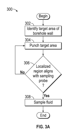
Fig. 3A is a flow diagram of an illustrative method 300 for increasing the
permeability
of a borehole wall. Processing logic (e.g., one or more of processing logic
203, 205 and/or 207)
performs the method 300 during a drilling process, meaning that the steps of
method 300 may
be performed when the drill bit 114 (Fig. 1) is operational, during periods
when the drill bit
114 is temporarily stopped, or both. Method 300 is now described in light of
Figs. 3B-3F,
which constitute an illustrative implementation of the method 300. The method
300 comprises
identifying a target area of a borehole wall from which formation fluid is to
be extracted (step
4
CA 02961722 2017-03-17
WO 2016/060689 PCT/US2014/061180
302). The target area may be identified by drilling personnel considering
various factors, such
as target area depth and permeability based on surface logs, adjacent well
logs and other
relevant data. Fig. 3B illustrates this step and denotes the target area of
the formation with
numeral 310. As shown, the punching tool 211¨and, in particular, gun charges
228¨are in
proximity to the target area 310.
The method 300 then comprises punching the target area 310 using the punching
tool
211 (step 304). The precise technique by which the target area is punched
varies according to
the punching tool 211 used. In the embodiment illustrated in Fig. 3C, punching
is performed
using perforation gun charges 228, as shown. The punch induces fissures in
localized region
312, thereby increasing the permeability of the region 312. As explained, the
localized region
312 is a region in the formation 200 that experiences an increase in
permeability due to punches
by the punching tool 211.
The method 300 also comprises determining whether the localized region¨i.e.,
the
region of the formation that has increased permeability as a result of the
punching in step 304-
aligns with the fluid sampling probe (step 306). A localized region is aligned
with the fluid
sampling probe if a plane of the fluid sampling probe that is orthogonal to
the axis of the tool
assembly coincides with the localized region. In addition, in some
embodiments, whether a
probe and a localized region are aligned depends on whether one or more
fissures in the
localized region are sufficiently close to the borehole wall 202 so that the
fluid is accessible to
the sampling probe. Sensor 226 performs this detection step 306 using any of a
variety of
known techniques to identify the spatial features of the fissures (e.g.,
length, width, height,
position, direction, concentration, total number, average volume, and/or total
volume) in the
localized region 312. As dashed line 314 indicates in Fig. 3D, the fluid
sampling probe 212
does not align with the localized region 312. Specifically, the localized
region 312 is farther
downhole than the fluid sampling probe 212. Thus, were the probe 212 extended
to the
formation 200, it would not benefit from the increased permeability of
localized region 312.
If the result of the determination at step 306 is that the localized region
does not align
with the sampling probe, the method 300 further comprises repeating steps 304
and 306 until
the localized region does align with the sampling probe. Fig. 3E illustrates
this repeated
punching process, in which gun charges 228 punch the formation 200 such that
the localized
region 312 increases in size until it aligns with the fluid sampling probe
212, as dashed line
314 indicates.
When the result of the determination at step 306 is that the localized region
aligns with
the sampling probe, the method 300 comprises sampling the formation fluid
(step 308). Fig.
5
CA 02961722 2017-03-17
WO 2016/060689 PCT/US2014/061180
3F illustrates such sampling, in which the sealing pad 210 extends away from
the tool assembly
201 and toward the borehole wall 202 until it forms a seal with the wall 202.
In some
embodiments, rams (not specifically shown) are extended from the opposite side
of the tool
assembly so that the pad 210 is forced into a sealing contact with the
borehole wall 202. The
probe 212 then samples the fluid as described above. In this way, the tool
assembly 201
increases the size of the localized region 312 until the region is accessible
to the sampling probe
212, thereby making it unnecessary to reposition the tool assembly 201 to
align the probe 212
and localized region 312.
In some embodiments, however, the tool assembly 201 may be repositioned in
lieu of
repeated punching¨for instance, in cases where additional punching would
negatively affect
the integrity of the borehole wall 202. Fig. 4A shows an illustrative method
400 for increasing
formation permeability in accordance with such embodiments. Processing logic
(e.g., one or
more of processing logic 203, 205 and/or 207) performs the method 400 during
the drilling
process, meaning that the steps of method 400 may be performed when the drill
bit 114 (Fig.
1) is operational, during periods when the drill bit 114 is temporarily
stopped, or both. Method
400 is now described in light of Figs. 4B-4F, which constitute an illustrative
implementation
of the method 400. The method 400 begins by identifying a target area of the
borehole wall
(step 402). Fig. 4B illustrates the target area using numeral 412. The method
400 further
comprises punching the target area 412 (step 404). Fig. 4C illustrates the gun
charges 228 of
punching tool 211 punching the target area to produce localized region 414. As
explained, the
localized region 414 is the area of the formation that increases in
permeability due to the
punching tool 211.
Method 400 then comprises determining whether the localized region 414 aligns
with
the fluid sampling probe 212 (step 406). In some embodiments, whether a probe
and a localized
region are aligned depends on whether one or more fissures in the localized
region are
sufficiently close to the borehole wall 202 so that the fluid is accessible to
the sampling probe.
Sensor 226 performs this detection step using any of a variety of known
techniques to identify
the spatial features of the fissures (e.g., length, width, height, position,
direction, concentration,
total number, average volume, and/or total volume) in the localized region
414.
Fig. 4D illustrates the case in which the localized region 414 does not align
with the
fluid sampling probe 212, as dashed line 416 denotes. In such cases, the
method 400 comprises
repositioning the fluid sampling probe 212 (step 410). Fig. 4E illustrates
such a repositioning
of the probe 212, in which the entire tool assembly 201¨that is, the drill
string itself¨is
repositioned within the borehole 112 such that the probe 212 aligns with the
localized region
6
CA 02961722 2017-03-17
WO 2016/060689 PCT/US2014/061180
414, as dashed line 416 denotes. Step 410 is performed in lieu of repeated
punching of the
target area. In some embodiments, the fluid sampling probe 212 is repositioned
by a distance
less than that between the position of the probe 212 (i.e., prior to
repositioning) and the
punching tool 211. Stated another way, in some embodiments, the fluid sampling
probe 212 is
repositioned by the minimum distance necessary for the probe 212 to access
fluid-containing
fissures in the localized region 414.
Regardless of the determination at step 406, the method 400 concludes by
sampling the
formation fluid (step 408). Fig. 4F illustrates such sampling, in which the
sealing pad 210 is
extended away from the tool assembly 201 and toward the borehole wall 202
until the pad
forms a seal with the wall 202. Rams are optionally used to enhance the seal,
as described
above with respect to method 300. The fluid sampling probe 212 then samples
fluid as
described above.
Some embodiments comprise both the repeated punching of the borehole wall as
well
as the repositioning of the tool assembly. Generally, in such embodiments, the
greater the
number and/or force of punches delivered to the formation, the greater the
size of the fissured,
localized region and the smaller the distance that the tool assembly must
subsequently be
repositioned to ensure alignment of the fluid sampling probe and the localized
region.
Numerous other variations and modifications will become apparent to those
skilled in
the art once the above disclosure is fully appreciated. For example, the steps
shown in methods
300 and 400 are merely illustrative, and various additions, deletions and
other modifications
may be made as desired and appropriate. Moreover, the systems and methods
disclosed herein
may be used to obtain additional, useful information. For instance, processing
logic may
compare the force with which a punching tool 211 punches a borehole wall 202
to the increase
in permeability in the punched area (e.g., as determined by sensor 226) to
draw conclusions
about the formation at the site of punching¨for instance, to determine a
permeability level
relative to other, similarly punched areas. Similarly, the illustrative
implementations described
herein (e.g., with respect to Figure 1) are merely exemplary; any and all
other such
implementations also fall within the scope of this disclosure. It is intended
that the following
claims be interpreted to embrace all such variations, modifications and
equivalents. In
addition, the term "or" should be interpreted in an inclusive sense.
The present disclosure encompasses numerous embodiments. At least some of
these
embodiments are directed to a drill string tool assembly that comprises a
punching tool that
induces fissures to increase permeability in a localized region of a borehole
wall. The assembly
also comprises a sensor that detects spatial features of the fissures and
processing logic, coupled
7
CA 02961722 2017-03-17
WO 2016/060689 PCT/US2014/061180
to the sensor and punching tool, that adapts operation of the punching tool
based on the spatial
features. The assembly further comprises a fluid sampling probe, coupled to
the processing
logic, that samples fluid from the localized region.
In addition, at least some of the embodiments are directed to a method that
comprises
punching a formation to create fissures in a localized portion of the
formation until at least one
of the fissures aligns with a fluid sampling probe, sampling formation fluid
from the localized
portion, and storing the formation fluid in a drill string tool assembly.
Further, at least some of the embodiments are directed to a method that
comprises
punching a borehole wall to create fissures in a localized region of a
formation, sensing spatial
features of the localized region, and using the spatial features to adjust a
position of a fluid
sampling probe such that the probe is aligned with the localized region.
The foregoing embodiments may be supplemented in any of a variety of ways,
including by adding any of the following, in any sequence and in any
combination: The drill
string tool assembly processing logic determines when the fluid sampling probe
is aligned with
the localized region and triggers operation of the fluid sampling probe when
it is so aligned.
The drill string tool assembly processing logic repositions the tool assembly
to align the fluid
sampling probe with the localized region. The drill string tool assembly
sensor is selected from
the group consisting of a fiber optic sensor and an electromagnetic sensor.
The drill string tool
assembly is contained within a single drill string sub. The drill string tool
assembly punching
tool is selected from the group consisting of a perforation gun, a laser, a
steam jet, a fluid jet, a
heating device, a hydraulic ram and a hammer. The drill string tool assembly
punching tool
induces fissures during a drilling operation, and the fluid sampling probe
also samples the fluid
during the drilling operation. The methods may further comprise determining
properties
associated with the localized portion by considering a force with which the
formation is
punched. The methods may comprise using either a fiber optic sensor or an
electromagnetic
sensor to punch the formation until at least one of the fissures aligns with
the fluid sampling
probe. In at least some of the methods, the drill string tool assembly is
contained within a single
drill string sub. In at least some of the methods, the punching comprises
using a tool selected
from the group consisting of a perforation gun, a laser, a steam jet, a fluid
jet, a heating device,
a hydraulic ram and a hammer. The methods may further comprise performing the
punching
and the sampling during a drilling operation. In at least some of the methods,
adjusting the
position of the fluid sampling probe comprises re-positioning the probe by a
distance less than
that between the probe and a punching tool used for the punching. In at least
some of the
methods, sensing comprises using either a fiber optic sensor or an
electromagnetic sensor. At
8
CA 02961722 2017-03-17
WO 2016/060689 PCT/US2014/061180
least some of the methods further comprise housing the fluid sampling probe
and a punching
tool used for the punching within a single drill string sub. At least some of
the methods further
comprise sampling fluid from the localized region during a drilling operation.
At least some of
the methods further comprise again punching the borehole wall to increase a
size of the
localized region.
9