Note: Descriptions are shown in the official language in which they were submitted.
CA 02961799 2017-03-20
WO 2016/044927
PCT/CA2015/050928
1
MOUNTING OF AN OPTICAL ELEMENT IN A BARREL
USING A FLEXIBLE RING
FIELD OF THE INVENTION
The present invention relates to mechanical components for optical systems and
more particularly concerns an optical assembly where one or more optical
elements are mounted in a barrel using a flexible ring.
BACKGROUND
Optical elements or components are omnipresent in devices, systems or
arrangements where light needs to be directed, expanded, focussed, collimated
or otherwise transformed or affected. Optical elements can for example be
embodied by lenses, mirrors, Diffractive Optical Elements (DOE), assemblies of
such elements, or the like.
In a typical optical system, most or all optical elements usually need to be
precisely positioned and aligned in order to properly perform their intended
optical function. This positioning and alignment typically involve securing
the
optical element in a holder or mount of some sort. Proper alignment of an
optical
element with respect to the holder is a delicate operation that generally
requires
tight manufacturing tolerances and careful handling.
Barrels are well known types of mechanical holders for optical elements.
Barrels
typically define a cylindrical cavity in which one or more optical elements
are
mounted. By way of example, a lens is a type of optical element that is often
mounted in barrels. A lens generally needs to be centered with a precision
that
can be of the order of a few micrometers. Opto-mechanical assemblies in which
lenses are mounted and precisely centered are known in the art. Referring to
FIG. 1 (PRIOR ART), there is shown a typical assembly 20 including a lens 22,
a
barrel 24 and a retaining ring 26. The lens 22 is mounted in the barrel 24
with the
periphery of one of its surfaces Si in contact with a lens seat 28. The
retaining
CA 02961799 2017-03-20
WO 2016/044927
PCT/CA2015/050928
2
ring 26 is typically threaded within the barrel 24 and abuts on the surface S2
of
the lens 22 opposite to the lens seat 28, thus securing the lens 22 in the
assembly 20. It is well known in the art that the lens is centered when the
centers
of curvature Cl and C2 of both surfaces Si and S2 lie on the center axis B of
the
lens barrel 24.
The technique consisting in inserting a lens in a lens barrel and then
securing the
lens with a threaded ring is generally referred to as the "drop-in" lens
technique.
The centering precision obtained from this technique first depends on the
minimum allowable radial gap between the lens and the barrel. Thermal effects
caused by the mismatch of the respective coefficients of thermal expansion of
the
lens and barrel materials also have an impact on the centering of the lens.
Manufacturing tolerances on dimensions of the components of the assembly
such as the diameter of the lens, the diameter of the barrel cavity and the
differences in thickness along the edge of the lens also affect the quality of
the
centering. The greater the precision required on the centering of the lens,
the
greater the manufacturing costs of both lens and barrel.
The main advantages of the drop-in technique are that the assembly time can be
very short and that the lenses are removable. Low cost drop-in has, however,
the
drawback of a lower centering precision. The drop-in method may not be
suitable
when higher precision is required, and then an active alignment is typically
chosen. In this centering method, the lens is first positioned inside the
cavity and
its decentering relative to the center axis of the barrel is measured. The
lens is
then moved to reduce the centering error. These steps can be repeated several
times until the alignment of the lens complies with the centering
requirements.
Once centered, the lens is fixed in place with adhesive or other means. This
method provides a very high level of centering accuracy, but requires
expensive
equipment while being time-consuming.
CA 02961799 2017-03-20
WO 2016/044927
PCT/CA2015/050928
3
While the discussion above concerns mainly lenses, other types of optical
elements can be mounted in a barrel using a retaining ring, and such elements
are confronted with the same issues discussed above.
There therefore remains a need for an approach to mount an optical element in
a
barrel which alleviates at least some of the drawbacks of known techniques.
SUMMARY
In accordance with one aspect, there is provided an optical assembly including
a
barrel defining a cavity, the barrel having an inner wall provided with a set
of
barrel threads. The optical assembly further includes an optical element
mounted
in the cavity and having opposite first and second surfaces, and a flexible
ring
having an abutment peripherally engaging one of the first and second surfaces.
The flexible ring has an outer perimeter provided with a set of ring threads
engaging the barrel threads. The flexible ring further has a biased state in
which
the ring threads press against the barrel threads. The flexible ring is
resiliently
deformable to a compressed state in which an engagement of the ring threads
and barrel threads allows screwing of the flexible ring within the cavity.
In some implementations, the flexible ring may include a gap, at least one
compressible portion or at least one resilient insert along a section thereof.
In accordance with another aspect, there is also provided an optical assembly
having a barrel defining a cavity, the barrel having an inner wall provided
with a
set of barrel threads, and a seat provided in the cavity. The optical assembly
further includes a plurality of optical subassemblies mounted in a cascade
within
the cavity. Each subassembly includes:
- an optical element mounted in the cavity and having opposite first
and second surfaces;
- a flexible ring having an abutment peripherally engaging the second
surface, the flexible ring having an outer perimeter provided with a
CA 02961799 2017-03-20
WO 2016/044927
PCT/CA2015/050928
4
set of ring threads engaging the barrel threads, the flexible ring
having a biased state in which the ring threads press against the
barrel threads, the flexible ring being resiliently deformable to a
compressed state in which an engagement of the ring threads and
barrel threads allows screwing of said flexible ring within the cavity.
The seat engages the first surface of an innermost one of the optical
elements,
and the first surface of each subsequent ones of the optical elements is
supported by the flexible ring of the previous subassembly within said
cascade.
In accordance with yet another aspect, there is provided an optical assembly,
including a barrel defining a cavity, the barrel having an inner wall provided
with a
set of barrel threads, and one or more optical subassemblies. Each optical
subassembly includes:
- an optical element mounted in the cavity and having opposite first
and second surfaces;
- a flexible ring having an abutment peripherally engaging one of the
first and second surfaces, the flexible ring having an outer
perimeter provided with a set of ring threads engaging the barrel
threads, the flexible ring having a biased state in which the ring
threads press against the barrel threads, said flexible ring being
resiliently deformable to a compressed state in which an
engagement of the ring threads and barrel threads allows screwing
of said flexible ring within the cavity.
Other features and advantages of the invention will be better understood upon
a
reading of embodiments thereof with reference to the appended drawings.
BRIEF DESCRIPTION OF THE DRAWINGS
FIG. 1 (PRIOR ART) is an illustration of a lens assembly showing a biconvex
lens
mounted in a lens barrel according to prior art.
CA 02961799 2017-03-20
WO 2016/044927
PCT/CA2015/050928
FIG. 2 is an exploded isometric view of an optical assembly according to one
embodiment.
FIG. 3 is a schematic top view of the optical assembly of FIG. 2; FIG. 3A is a
5 cross-sectional view taken along line AA of FIG. 3; FIG. 3B is an
enlarged view of
a portion of FIG. 3A showing the engagement of the first surface of the
optical
element on the seat of the barrel; FIG. 3C is an enlarged view of a portion of
FIG.
3A showing the engagement of the ring threads with the barrel threads.
FIGs. 4A and 4B are isometric views of a flexible ring having a gap therein,
respectively shown in a biased state and in a compressed state.
FIGs. 5A and 5B are isometric views of flexible rings respectively having a
compressible portion and a resilient insert; FIG. 5C and 5D are respectively
an
isometric view and a top view of a resilient ring where the ring threads are
split
into three ring thread segments.
FIG. 6 is a cross-sectional view of an optical assembly according to one
embodiment where the barrel threads and ring threads each have a load-bearing
thread face perpendicular to the center axis of the cavity. FIG. 6A is an
enlarged
view of a portion of FIG. 6 showing the engagement of the ring threads with
the
barrel threads.
FIG. 7 is a schematic illustration of an optical assembly according to one
embodiment, where a sleeve is mounted in the cavity using a flexible ring.
FIG. 8 is a schematic illustration of an optical assembly according to one
embodiment, where a flexible ring is used as a seat for an optical element.
CA 02961799 2017-03-20
WO 2016/044927
PCT/CA2015/050928
6
FIG. 9A and 9B are respectively a cross-sectional and an exploded isometric
view of an optical assembly including a plurality of subassemblies mounted in
a
cascade within the cavity of a barrel.
DETAILED DESCRIPTION OF EMBODIMENTS
The description below relates to optical assemblies where one or more optical
elements are mounted in the cavity of a barrel.
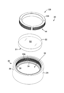
Referring to FIGs. 2, 3 and 3A to 3C, there is shown an optical assembly 20
according to one embodiment. The optical assembly 20 includes a barrel 24
defining a cavity 32, and an optical element 22 mounted in the cavity 32.
The barrel 24 may be embodied by any housing structure in which an optical
element 22 is to be mounted, aligned and secured in position. Typical barrels
such as the ones illustrated herein include a hollow cylindrical housing 30
having
an inner wall 34 and an outer wall 36. The inner wall 34 of the barrel 24 is
provided with a set of barrel threads 42a, which will be described further
below.
The hollow portion of the cylindrical housing 30 forms the cavity 32, which
may
have any shape adapted to receive the optical element 22 therein. The cavity
32
has a center axis B, defined as its symmetry axis.
It will be readily understood that the barrel 24 may have any shape,
mechanical
features or additional components adapted to engage, connect to or otherwise
interact with other structures as required by the context in which the optical
element 22 is to be used. For example, the outer wall 36 of the barrel may be
provided with threads, holes, pins, projections, flanges and the like without
departing from the scope of the invention. Alternatively, the barrel 24 may be
an
integral part of a larger optical assembly, such as for example a camera
objective
or a microscope objective.
CA 02961799 2017-03-20
WO 2016/044927
PCT/CA2015/050928
7
In the illustrated example of FIGs. 2, 3 and 3A to 3C, the optical element 22
is a
biconvex lens. However, in other implementations the optical element 22 may be
any component or group of components acting on light in some fashion, for
example to direct or change the direction of a light beam, focus or expand,
collimate, filter, or otherwise transform or affect light. Examples of optical
elements include lenses of any type, such as for example, piano-convex,
biconvex, piano-concave, biconcave, positive or negative meniscus lenses.
Cemented doublet or triplet lenses of the types listed above can also be
centered
according to the present description. The optical element may also be embodied
by diffractive lenses, mirrors, diffractive optical elements (DOEs), pinholes,
or the
like. The optical element may have spherical or aspherical surfaces and may
have an off-axis profile. In other embodiments, the optical element may be
embodied by a more complex subassembly of optical components such as for
example one or more lenses mounted in a sleeve, a mirror or a lens mounted in
a
spider, a lens or a lens barrel mounted in an optical mount which is itself
mounted on an optical bench, etc.
The optical element 22 has opposite first and second surfaces Si and S2. It
will
be noted that throughout the present description, the "first" surface Si
denotes by
convention the surface facing away from the opening of the cavity through
which
the optical element has been inserted, that is, the surface being inserted
first
when mounting the optical element in the barrel. The "second" surface S2
therefore extends on the side of the opening of the cavity from which the
optical
element has been inserted. It will be understood that this convention is used
for
ease of reference only and is not meant to confer any particular ranking or
preferred orientation or characteristics to either surface.
The optical assembly 20 further includes a flexible ring 126. The flexible
ring 126
has an abutment 44 peripherally engaging either the first surface Si or the
second surface S2 of the optical element 22. In the illustrated embodiment of
FIGs. 2, 3 and 3A to 3C, the abutment 44 of the flexible ring 126 engages the
CA 02961799 2017-03-20
WO 2016/044927
PCT/CA2015/050928
8
second surface S2, and the optical assembly 20 includes a seat 28 provided in
the cavity 32 and engaging the first surface Si of the optical element 22. The
optical element 22 is therefore secured between the seat 28 and the flexible
ring
126. In other implementations, the abutment of the flexible ring may engage
the
first surface Si of the optical element, the abutment thereby defining a seat
for
the optical element. Such an embodiment will be described further below.
Referring more particularly to FIGs. 3A and 3B, in some embodiments the seat
28 may be defined by an annular shoulder 38 formed in the inner wall 34 of the
barrel 24 projecting inwardly within the cavity 32. As best seen in FIG. 3B,
in the
illustrated embodiment the shoulder 38 is shown as forming a right angle with
respect to the inner wall 34 of the barrel 24, such that the first surface Si
rests on
the corner edge 40 of the shoulder 38. Optionally, as illustrated, the corner
edge
40 can be rounded or bevelled by polishing or machining to avoid damaging the
first surface Si of the optical element 22. It will be readily understood that
in
other embodiments the contact between the first surface Si and the seat 28 may
be different, and can for example be an edge contact, a tangential contact, a
toroidal contact or a spherical contact. Furthermore, in some embodiments the
seat 28 need not extend along the entire circumference of the inner wall 34 of
the
barrel but may include missing portions or other discontinuities, or may be
embodied by a plurality of radially aligned projections spaced apart along the
inner wall. In other implementations, the seat 28 may be embodied by a
separate
element affixed to the barrel, such as for example a ring-shaped component
screwed to the barrel or otherwise affixed to the barrel.
Referring more particularly to FIG. 3C, the abutment 44 of the flexible ring
126
may for example be defined by a bevelled inner edge of the flexible ring 126
which contacts a peripheral region 27 of the second surface S2 of the optical
element 22. Optionally, as illustrated in the embodiment of FIG. 3C, the
abutment
44 may include in a rounded corner to avoid damaging the second surface S2.
However, in other embodiments the abutment may have a straight edge shape.
CA 02961799 2017-03-20
WO 2016/044927
PCT/CA2015/050928
9
Various types of engagements may be considered, such as for example an edge
contact, a tangential contact, a toroidal contact or a spherical contact. It
will be
readily understood that the abutment 44 may alternatively be embodied by
different structures allowing a suitable contact between the flexible ring 126
and
the peripheral region 27 of the second surface S2. For example, in some
assemblies the abutment 44 may have an irregular shape providing distributed
discrete points of contact with the peripheral region of the second surface
S2.
In typical implementations where the optical element 22 is secured between the
seat 28 and the flexible ring 126, the optical assembly 20 allows for some
movement of the first surface Si of the optical element relative to the seat
28 and
of the second surface S2 of the optical element relative to the abutment 44 of
the
flexible ring 126. As will be readily understood by one skilled in the art,
this
implies that the optical element 22 meets the so-called "self-centering"
criterion
known in the art. Self-centering refers to the capacity of the optical element
22 to
roll or slide on the seat 28. One skilled in the art would therefore call
"self-
centered" an optical element that has a coefficient of friction with respect
to the
seat and flexible ring sufficiently small to allow a rolling or other movement
of the
optical element during tightening of the flexible ring. As for example known
from
Paul Yoder Jr., "Mounting Optics in Optical Instruments", SPIE Press (2008),
the
threshold for the coefficient of friction can be expressed as:
< Yd. 17c2
(1)
2R1 2R2
where:
= p is the coefficient of friction between the optical element and the seat or
flexible ring;
= Ycl is the half-diameter of contact of the first surface Si of the
optical
element with the seat;
CA 02961799 2017-03-20
WO 2016/044927
PCT/CA2015/050928
= Yc2 is the half-diameter of contact of the second surface S2 of the
optical
element with the flexible ring;
= R1 is the radius of curvature of the first surface of the optical
element; and
= R2 is the radius of curvature of the second surface of the optical
element.
5
It is to be noted that in equation (1) the radius of curvature of each surface
has a
positive value for convex surfaces and a negative value for concave surfaces.
Referring to FIG. 2, 3, 3A and more specifically to FIG. 3C, the flexible ring
126
10 has an outer surface 129 around its perimeter provided with a set of
ring threads
42b. The ring threads 42b engage the barrel threads 42a when the flexible ring
126 is inserted into the cavity 32 of the barrel 24.
The expression "threads" is meant to refer to engageable helicoidal
projections
on two components allowing one component to be screwed on or within the
other. By convention, a single thread is generally considered to be the
portion of
a helicoidal projection corresponding to one screw turn, whereas the length of
the
projection defining the entire screw path is referred to as threading or a set
of
threads. As explained above, the barrel threads 42a are disposed along the
inner
wall 34 of the barrel 24 whereas the ring threads 42b are along the outer
perimeter 129 of the flexible ring 126, such that the flexible ring can be
screwed
inside the cavity 32. It will be readily understood that either set of threads
42a,
42b need not be continuous along the entire screw path, but may include
missing
segments or other discontinuities as long as sufficient contact points are
provided
to allow engagement of the barrel and ring threads.
The barrel threads 42a and ring threads 42b have complementary thread
profiles.
The expression "thread profile" refers to the cross-sectional shape, angle and
pitch formed by the threads of a given set. By definition, the thread angle is
the
angle formed by the opposite walls of a thread, while the pitch of a thread
set is
the spacing between two consecutive crests in a set of threads. By
CA 02961799 2017-03-20
WO 2016/044927
PCT/CA2015/050928
11
complementary , it is understood that the profiles of the barrel threads 42a
and ring threads 42b are such that they can be screwed together, which usually
involves a same pitch. In various implementations of the present optical
assembly, various thread profiles may be used for the barrel and ring threads
42a, 42b. By way of example, in the illustrated embodiment of FIG. 3C a
triangular profile having a thread angle 01
threads of 600 is shown, which is
representative of a common thread standard. A thread angle of 55 is also
commonly used for mounting optical components, although other thread angles
may also be used. In common variants, the thread profile may have a
trapezoidal
shape, the crests and grooves of the threads may have a rounded profile, or
the
crest of each thread may be truncated. In other variants, the thread profiles
may
be non-symmetrical, that is, the opposite walls of a thread may be oriented at
different angles with respect to a plane perpendicular to the center axis of
the
cavity, as explained in further details below. Of course, the shapes and
thread
angles mentioned herein are given by way of example only and should not be
construed as exhaustive representations of possible thread profiles.
As explained above, it is desirable for many applications to center the
optical
element in the cavity with great precision. In optical assemblies such as
shown in
FIG. 2, 3 and 3A to 3C, the alignment of the optical element 22 within the
cavity
32 is impacted by both the engagement of the first surface Si with the seat
28,
and the engagement of the second surface S2 with the flexible ring 126.
One skilled in the art will understand that the centering error of the surface
Si
according to the center axis B of the barrel 24 depends on the concentricity
of the
seat 28 and on any manufacturing error in its perpendicularity relative to the
center axis B. In some implementations, these manufacturing errors can be kept
very low by using suitable manufacturing practices. For example, currently-
available techniques can provide centering errors typically less than 5 pm.
CA 02961799 2017-03-20
WO 2016/044927
PCT/CA2015/050928
12
On the side of its second surface S2, the alignment of the optical element 22
within the cavity is in direct relation with the position and orientation
(tilt) of the
flexible ring 126 within the cavity. For prior art assemblies of the type
shown in
FIG. 1 (PRIOR ART), on the one hand, the retaining ring 26 has a lateral play
within the cavity 32, allowing its center to be shifted laterally by a few
tens of
micrometers on either side of the center axis B. This is referred to as the
decentering of the retaining ring. On the other hand, a decentered threaded
retaining ring 26 will also have an inherent tilt with respect to the center
axis B of
the cavity, resulting from the sloped faces of the barrel and ring threads.
Both
decentering and tilt of the retaining ring 26 contribute to the centering
error of the
second surface S2 of the optical element 22.
Referring to FIG. 4A and 3C, in accordance with one aspect, the flexible ring
126
has a biased state in which the ring threads 42b press against the barrel
threads
42a. In other words, in the biased state the flexible ring 126 extends
transversally
across the full extent of the cavity 32, so that the tips of the crests of the
ring
threads 42b contact the deepest points of the grooves of the barrel threads
42a.
As will be readily understood by one skilled in the art, the pressing of the
ring
threads against the barrel threads prevents a lateral shift of the flexible
ring 126
within the cavity, therefore eliminating the decentering observed with
conventional retaining rings. The centering error imposed on the optical
element
22 when secured by the flexible ring 126 can therefore be minimized.
Additionally, it can be shown that the tilt of a retaining ring is
intrinsically linked to
its lateral decentering, and that the relationship between these two factors
can be
expressed as follows:
[2Aring tan CP threads 12) (2)
Oring = sin-1 _________________________________________
dring
where:
CA 02961799 2017-03-20
WO 2016/044927
PCT/CA2015/050928
13
= Oring(degrees) is the tilt of the retaining ring;
= Aring(mm) is the lateral decentering of the retaining ring;
= yothreads(degrees) is the thread angle of the ring and barrel threads;
and
= dring (mm) is the major diameter of the retaining ring (measured at the
thread crest).
It will be readily observed that by minimizing the lateral decentering Aring,
the tilt
Bring is also minimized. The use of a flexible ring having a biased state in
which
the ring threads 42b press against the barrel threads 42a can therefore
significantly reduce the centering error imposed on the optical element 22 by
the
flexible ring 126 when compared to conventional retaining rings known in the
art.
With reference to FIG. 4B, the flexible ring 126 is also resiliently
deformable to a
compressed state in which the engagement of the ring threads and barrel
threads
allows screwing of the flexible ring 126 within the cavity. Advantageously, by
temporarily reducing the diameter of the flexible ring 126, this flexible ring
can be
inserted in the cavity and rotated with the ring threads engaged with the
barrel
threads, which would be difficult or impossible when the flexible ring is in
the
biased state. When in the compressed state, the flexible ring 126 can
therefore
be screwed in the cavity until it reaches the desired position, where it abuts
on
the second surface of the optical element to secure it. Once released from the
compressed state, the spring constant of the flexible ring tends to bias the
flexible
ring, so that the ring threads press on the barrel threads, therefore
eliminating the
lateral play on the position of the flexible ring.
Still referring to FIGs. 4A and 4B, in accordance with one implementation the
flexible ring 126 may include a gap 130 machined along a section thereof. The
flexible ring is preferably made of a resilient material such as metals or
plastics.
Preferably, the material of the flexible ring has a spring constant allowing
for the
ring to be compressed and resiliently return to the biased position with an
CA 02961799 2017-03-20
WO 2016/044927
PCT/CA2015/050928
14
outward radial force sufficient to remove the diametric clearance between the
flexible ring 126 and the barrel threads 42a.
It will be readily understood that the physical parameters of the flexible
ring 126
such as its constituting material or materials, dimensions, and overall
profile may
be selected to optimize its spring constant in view of the desired biased and
compressed states. On the one hand, a large spring constant may result in a
large biasing force against the barrel threads which could lead to damages to
the
barrel threads and or ring threads. On the other hand, a low spring constant
may
be insufficient to hold the flexible ring in place within the cavity, leading
to the
potential of misalignment and in the worst case disengagement of the ring
threads from the barrel threads. One skilled in the art will be able to find
the
suitable spring constant for a given implementation in view of the parameters
of a
particular optical assembly.
The flexible ring 126 may additionally be designed so as to ensure a maximal
circularity of the flexible ring 126 in both biased and compressed states. As
will
be readily understood by one skilled in the art, manufacturing a complete ring
made up of a resilient material and subsequently removing a small section to
create a gap typically results in a slight widening of the gap. In some
implementations, the flexible ring preferably has a nominal diameter prior to
the
gap being formed which is equal or very close to the diameter of the cavity 32
(the nominal diameter of the flexible ring being measured from crest-to-crest
of
the ring threads on opposite sides of the flexible ring whereas the diameter
of the
cavity is measured from the deepest point of grooves of the barrel threads on
opposite sides of the cavity). This may avoid the flexible ring taking an oval
shape when in either the biased or the compressed state.
As shown in FIGs. 4A and 4B, the flexible ring 126 may include one or more
tool-
engaging structure provided on a surface 137 of the flexible ring 126 facing
outwardly of the cavity. The tool-engaging structures may provide a hold for a
CA 02961799 2017-03-20
WO 2016/044927
PCT/CA2015/050928
snap ring tool or pliers or other similar devices. Once engaged with the tool-
engaging structures, the tool may be used to apply a compressing force F, on
the
flexible ring 126, deforming it to its compressed state, and then impose a
rotational movement allowing the screwing of the flexible ring 126 within the
5
cavity. Once the flexible ring is close to its final position, the compressing
force
may be discontinued, releasing the flexible ring to expand to its biased
state, and
the tool disengaged from the tool-engaging structures. Of course, the reverse
procedure may be used to unscrew the flexible ring from the cavity if needed.
Such embodiments may advantageously reduce friction between the barrel
10
threads and ring threads during the insertion of the flexible ring. By way of
example, in the illustrated embodiments the tool-engaging structures are
implemented by a pair of engagement holes 138 symmetrically disposed on the
surface 137 with respect to the gap 130. The tool-engaging structures may
alternatively be embodied by notches, protrusions, hooks, or by any other
15
structure which may serve the purpose of interacting with a tool to set the
flexible
ring 126 in a compressed state that will allow screwing or unscrewing it
within the
cavity. It will however be readily understood that the use of a tool and the
provision of tool-engaging structures are not essential to the present
invention.
Referring to FIG. 5A, there is shown another implementation of the flexible
ring
126 where a compressible portion 134 is provided along a section of the
flexible
ring 126 opposite to the gap 130. The compressible portion 134 may for example
be provided by weakening the corresponding section of the flexible ring 126 to
reduce its rigidity, therefore allowing the compression of the flexible ring
126. In
the illustrated implementation, the compressible portion 134 is for example
embodied by a circular notch made into the inner surface of the flexible ring
126.
In other variants, multiple compressible portions may be provided at different
positions along the flexible ring. FIG. 5B shows yet another variant where the
flexible ring 126 includes at least one resilient insert 136 along a section
thereof.
The resilient insert 136 may for example be a segment of a material of greater
resiliency than the remainder of the flexible ring 126. In one implementation,
a
CA 02961799 2017-03-20
WO 2016/044927
PCT/CA2015/050928
16
section of the flexible ring 126 may be removed, creating a gap, which is
subsequently filled by the resilient insert 136.
Referring to FIGs. 5C and 5D, there is shown yet another variant of a flexible
ring
126. In this variant, as with the embodiment of FIG. 5A, the flexible ring
includes
a gap 130 and a compressible portion 134 diametrically opposed to the gap. The
ring threads 42b are distributed around the flexible ring 126 according to
three
ring thread segments 142 projecting outwardly from the outer surface 129 of
the
flexible ring 126. In the illustrated example, one of the ring thread segments
is
disposed along the section of the ring in which the compressible portion 134
is
provided, whereas the other two ring thread segments 142 are positioned on
either sides of the gap 130. Preferably, the ring thread segments 142 are
equidistant at about 120 from each other, although a non symmetrical or
irregular distribution may be considered as well. Such an embodiment may
advantageously provide a more circular configuration of the ring threads 42b.
Although three ring thread segments are illustrated in FIGs. 5C and 5D, one
skilled in the art will understand that the flexible ring 126 may comprise a
different
number of ring thread segments.
Referring back to FIGs. 2, 3 and 3A to 3C, in the illustrated optical
assembly,
when the flexible ring 26 is screwed within the cavity 32 of the barrel 24 and
abuts on the optical element 22, the resulting mechanical forces in the system
typically act to push the flexible ring 126 away from the optical element 22.
In the
illustrated reference frame of FIG. 3C, it can be seen that the barrel 24 and
the
flexible ring 126 are engaged in such a manner that the top surface 104 of
each
ring thread 42b pushes against the bottom surface 102 of a barrel thread 42a
that
faces it. It will be understood that the reference to "top" and "bottom"
directions is
used herein as shorthand for ease of reference to FIG. 3C, and is not meant to
impart any preferential orientation to the optical assembly. As the load of
the
engagement between the barrel and ring threads is borne by the top surface 104
CA 02961799 2017-03-20
WO 2016/044927
PCT/CA2015/050928
17
of the ring threads 42b and the bottom surface 102 of the barrel threads 42b,
these latter surfaces are deemed to be the "load-bearing" faces of the
threads.
Referring to FIGs. 6 and 6A, in some implementations, the thread profiles of
the
barrel and ring threads 42a and 42b are such that their load-bearing faces 102
and 104 are perpendicular to the center axis B of the cavity. In the reference
frame of FIG. 6, the load-bearing faces therefore extend horizontally. It can
also
be said that the load-bearing thread faces 102 and 104 are perpendicular to
the
screw direction of the flexible ring 126 within the barrel 24, since this
direction is
parallel to the center axis B of the cavity. In the illustrated embodiment,
the
thread faces 106, 108 opposite to the load-bearing faces are slanted, making
an
acute angle of about 45 with the load-bearing thread faces 102, 104. The
resulting threads are otherwise known in the art as "Buttress" threads. Of
course,
the slanted thread faces 106, 108 could have an angle differing from 45
without
departing from the scope of the invention. Advantageously, in assemblies using
threads with load-bearing faces perpendicular to the center axis B of the
cavity,
there are no radial forces applied to the flexible ring 126 by the orientation
of the
barrel and ring threads, ensuring that the threads remain engaged.
Additionally,
such a thread profile can reduce the tilt on the flexible ring and the
corresponding
contribution on the decentering of the optical element. Further details on the
use
of such a type of threads in optical assemblies is provided in U.S. patent
application no. 14/803,865 (LAMONTAGNE), filed on July 20, 2015 and entitled
"Optical assemblies with tilt-controlled mounting of an optical element in a
barrel'.
Referring to FIG. 7, there is shown an embodiment of an optical assembly 20
where the optical element 22 is embodied by a sleeve 54 inserted inside the
cavity 32 of the barrel 24 and held therein by the flexible ring 126. The
sleeve has
opposite lower and upper ends 58 and 60 respectively defining the first and
second surfaces 51 and S2.
CA 02961799 2017-03-20
WO 2016/044927
PCT/CA2015/050928
18
One or more optical components 56a, 56b, 56c can be mounted in the sleeve 54.
Although three such optical components 56a, 56b, 56c are shown in FIG. 7, it
will
be readily understood that in different variants the number of optical
components
may vary. Each optical component 56a, 56b, 56c may for example be embodied
by a lens, a curved mirror, a diffractive optical element, a pinhole or the
like.
Preferably, each optical component 56a, 56b, 56c is centered with respect to
the
sleeve 54, such that proper centering of the sleeve 54 in the cavity 32 will
in turn
center the optical components 56a, 56b, 56c with respect to the center axis B
of
the cavity 32. In various implementations, the optical components 56 may be
mounted in the sleeve 54 using the common "drop-in" approach, and may be
held in place using a threaded ring, a snap ring, a flexure, an elastomeric
retainer, a burnished edge or any other suitable means. In some embodiments,
one or more of the optical components may be auto-centered within the sleeve
54 using a threaded retaining ring 26 in accordance with the principle
explained
in U.S. Pat. Appl. Pub. No. U52015/0131175 (LAMONTAGNE et al.), and
entitled "Auto-centering of an optical element within a barrel'. The optical
components 56 may also be centered according to a different technique, for
example an active alignment followed by bonding of the optical components.
Referring to FIG. 8, there is illustrated an optical assembly 20 according to
another implementation. In this embodiment, the abutment 44 of the flexible
ring
126 engages the first surface 51 of the optical element 22. The abutment 44
therefore defines a "seat" for the optical element 22. Advantageously, using a
flexible ring 126 having a biased state in which the ring threads 42b press
against
the barrel threads 42a mitigates the centering error on the seat, thereby
limiting
the contribution of the seat to the overall decentering of the optical element
22. In
the illustrated embodiment, a retaining ring 26 engages the second surface S2
of
the optical element 22, to secure the optical element 22 between the flexible
ring
126 and the retaining ring 26. The retaining ring may engage the second
surface
S2 of the optical element 22 and the barrel threads 42a in one of several
manners preserving the centering of the optical element 22 within the cavity.
In
CA 02961799 2017-03-20
WO 2016/044927
PCT/CA2015/050928
19
the illustrated embodiment of FIG. 8, the second surface S2 is planar and the
barrel threads 42a and the ring threads 42b have load-bearing faces
perpendicular to the center axis B of the cavity. In other variants, for
example
where the second surface is convex, the engagement of the retaining ring 26
and
the second surface S2 may meet an auto-centering condition as explained in the
above-mentioned U.S. Pat. Appl. Pub. No. US 2015/0131175 (LAMONTAGNE et
al.). In some implementations, the retaining ring 26 may also be a flexible
ring
such as described above. In other variants, the optical element 22 may be
bonded to the abutment 44 of the flexible ring 126, for example using glue or
the
like, in which case the retaining ring 26 may be omitted from the optical
assembly.
Referring to FIG. 9A and 9B, there is shown another implementation of an
optical
assembly 20. In this embodiment, the assembly includes a plurality of
subassemblies 140 mounted in a cascade within the cavity 32 of the barrel 24.
In
the illustrated example of FIGs. 9A and 9B only two subassemblies 140, 140'
are
shown, but one skilled in the art will readily understand that a greater
number of
subassemblies could be provided in the same cavity without departing from the
scope of the invention.
Each subassembly 140, 140' includes an optical element 22, 22' having opposite
first and second surfaces 51, 51' and S2, S2', and further includes a flexible
ring
126, 126'. As explained above, the flexible ring 126, 126' includes an
abutment
44, 44', which in this case peripherally engages the second surface S2, S2' of
the
corresponding optical element 22, 22'. The flexible ring 126, 126' of each
subassembly 140, 140' has a biased state and is resiliently deformable to a
compressed state such as explained above.
In the illustrated implementation, the optical assembly 20 includes a seat 28
provided in the cavity 32. As with previously described embodiments, the seat
may be defined by an annular shoulder 38 formed in the inner wall of the
barrel
CA 02961799 2017-03-20
WO 2016/044927
PCT/CA2015/050928
24 and projecting inwardly within the cavity 32, or may alternatively be
embodied
by any other suitable structure as listed above. In other variants, the seat
may be
embodied by an additional flexible ring (not shown) having characteristics
similar
to those of the flexible ring 126, 126' described herein. The seat 28 engages
the
5 first
surface Si of the innermost optical element 22, that is, the first optical
element 22 of the subassembly 140 inserted in the cavity 32. The flexible ring
126 included in the same subassembly 140 serves to secure the innermost
optical element 22 against the seat 28, as explained above. The opposite side
of
this flexible ring 126 is then used as a "seat" for the optical element 22' of
the
10 next
subassembly 140'. Advantageously, as the flexible ring 126 is precisely
centered within the cavity, it can help to mitigate centering errors on the
first
surface Si' of the next optical element 22'. In this manner, the first surface
Si' of
each optical element 22' subsequent to the first one 22 is supported by the
flexible ring 126 of the previous subassembly 140 within the cascade. The
15
flexible ring 126 therefore acts as a spacer between consecutive optical
elements
22, 22'.
It will be readily understood that the combinations of the illustrated
variants and
described embodiments are provided by way of example only and should not be
20
limitative of the scope of the invention. For example, although the drawings
mainly show optical elements embodied by biconvex and piano-convex lenses, it
will be readily understood that the other types of optical elements listed
above
may be used in combination with any of the illustrated configurations.
Of course, numerous modifications could be made to the embodiments described
above without departing from the scope of the invention as defined in the
appended claims.