Note: Descriptions are shown in the official language in which they were submitted.
CA 2962032 2017-03-22
- 1 -
DESCRIPTION
[Title of Invention]
METHOD FOR EVALUATING THERMAL PLASTICITY OF COALS AND CAKING
ADDITIVES, AND METHOD FOR PRODUCING COKE
[Technical Field]
[0001]
The present invention relates to a method for evaluating
thermal plasticity of coals and caking additives during
carbonization. The method is one of the approaches for
evaluating the quality of coking coals and caking additives.
The invention also relates to a method for producing coke
using the evaluation method.
[Background Art]
[0002]
In a blast furnace method which is the most common method
for pig iron production, coke plays a number of roles, for
example as a reducing agent for iron ore, as a heat source and
as a spacer. In order to operate a blast furnace stably and
efficiently, it is important that the gas permeability in the
blast furnace be maintained. Thus, there has been a need for
high-strength coke to be produced. Coke is produced by
carbonization of a coal blend, which is a blend of various
types of coking coals that have been crushed, in a coke oven.
During carbonization, coking coal softens and melts at
CA 2962032 2017-03-22
- 2 -
temperatures in the range of about 300 C to 550 C and, at the
same time, volatile matters are driven off to form a gas which
causes swelling, whereby particles are adhered together to
give a mass of semicoke. The semicoke is thereafter densified
by being contracted in the course where the temperature is
raised to near 1000 C, resulting in a rigid coke (a coke cake).
Thus, the adhesiveness of thermally plastic coal greatly
influences properties such as coke strength and particle
diameter after carbonization.
[0003]
In order to enhance the adhesion of coking coal (coal
blend), a coke producing method is generally adopted in which
a coal blend is mixed with a caking additive that exhibits
high fluidity at temperatures where the coal becomes softened
and molten. Here, examples of the caking additives include tar
pitches, petroleum pitches, solvent-refined coals and solvent-
extracted coals. Similarly to coal, the adhesiveness of these
caking additives in a thermally plastic state greatly affects
coke properties after carbonization.
[0004]
In the production of coke in a coke oven, carbonized coke
is discharged from the coke oven with a pushing machine. If
the degree of shrinkage of the produced coke cake itself is
low, discharging out of the oven becomes difficult. This can
lead to a "stickers (or hard push)", namely, a problem in
CA 2962032 2017-03-22
- 3 -
which the coke cannot be discharged from the oven. The
structure of a carbonized coke cake is largely affected by
volume changes of coal and semicoke during the carbonization
process. It is known that the shrinkage of semicoke has a good
correlation with the volatile content of coal (see, for
example, Non Patent Literature 1). In many cases, the volatile
contents of coal blends are controlled to be substantially
constant for operations in the same plant. Thus, volume-change
characteristics of plastic coal greatly affect the structure
of a carbonized coke cake.
[0005]
As mentioned above, thermal plasticity of coal is very
important due to their great influences on coke properties and
coke cake structures after carbonization. Thus, methods for
measuring these characteristics have been studied actively
since old times. In particular, coke strength, which is an
important coke quality, is largely affected by properties of
raw-material coal, especially coal rank and thermal plasticity.
Thermal plasticity is exhibited when coal becomes softened and
molten when heated, and are usually measured and evaluated
with respect to properties such as fluidity, viscosity,
adhesiveness and swellability of thermally plastic coal.
[0006]
Of the thermal plasticity of coal, the fluidity of
thermally plastic coal is commonly measured by a coal fluidity
CA 2962032 2017-03-22
- 4 -
testing method based on a Gieseler plastometer method
specified in JIS M 8801. According to a Gieseler plastometer
method, coal that has been crushed to sizes of not more than
425 tm is placed in a prescribed crucible and is heated at a
specified temperature increase rate while the rotational speed
of a stirring rod under a specified torque is read on a dial
and is indicated in terms of ddpm (dial division per minute).
[0007]
While a Gieseler plastometer method measures the
rotational speed of a stirring rod under a constant torque,
other methods evaluate the torque at a constant rotational
speed. For example, Patent Literature 1 describes a method in
which the torque is measured while rotating a rotor at a
constant rotational speed.
[0008]
Aimed at measuring viscosity that is a physically
significant thermal plasticity, there are methods for
measuring viscosity with a dynamic viscoelastometer (see, for
example, Patent Literature 2). Dynamic viscoelastometry is a
measurement of viscoelastic behaviors observed when a
viscoelastic body is subjected to periodic forces. In the
method described in Patent Literature 2, the viscosity of
thermally plastic coal is evaluated based on complex viscosity
coefficient among parameters obtained by the measurement. This
method is characterized in that the viscosity of thermally
CA 2962032 2017-03-22
- 5 -
plastic coal is measurable at a given shear rate.
[0009]
Further, it has been reported that thermal plasticity of
coal is evaluated by measuring the adhesion of thermally
plastic coal with respect to activated carbon or glass beads.
In such a method, a small amount of a coal sample, sandwiched
vertically between activated carbons or glass beads, is heated
to thermal plasticity and is thereafter cooled, and the
adhesion of the coal with respect to the activated carbons or
the glass beads is visually observed.
[0010]
A common method for measuring the swellability of
thermally plastic coal is a dilatometer method specified in
JIS M 8801. In a dilatometer method, coal that has been
crushed to sizes of not more than 250 m is compacted by a
specified method, placed into a prescribed crucible and heated
at a specified temperature increase rate while the
displacement of the coal is measured over time using a
detection rod arranged on the top of the coal.
[0011]
In order to simulate thermally plastic behaviors of coal
in a coke oven, coal swellability testing methods are known
which achieve enhanced simulation of permeation behaviors for
a gas generated during the plasticization of coal (see, for
example, Patent Literature 3). According to such a method, a
CA 2962032 2017-03-22
- 6 -
permeable material is arranged between a coal layer and a
piston or is arranged between a coal layer and a piston as
well as at the bottom of the coal layer so as to increase
pathways through which volatile matters and liquid substances
generated from the coal can pass, thereby approximating the
measurement environment more closely to an environment in
which swelling behaviors actually occur in a coke oven. A
similar method is also known in which the swellability of coal
is measured by arranging a material having a through pathway
onto a coal layer and microwave-heating the coal while
applying a load thereto (see Patent Literature 4).
[Citation List]
[Patent Literature]
[0012]
[PTL 1] Japanese Unexamined Patent Application
Publication No. 6-347392
[PTL 2] Japanese Unexamined Patent Application
Publication No. 2000-304674
[PTL 3] Japanese Patent No. 2855728
[PTL 4] Japanese Unexamined Patent Application
Publication No. 2009-204609
[Non Patent Literature]
[0013]
[NPL 1] C. Meyer et al.: "Gluckauf Forshungshefte", Vol.
42, 1981, pp. 233-239
CA 2962032 2017-03-22
- 7 -
[NPL 2] Morotomi et al.: "Journal of the Fuel Society of
Japan", Vol. 53, 1974, pp. 779-790
[NPL 3] D. W. van Krevelen: "Coal", 1993, pp. 693-695
[NPL 4] Miyazu et al.: " Nippon Kokan Gihou (Nippon Kokan
Technical Report)", Vol. 67, 1975, pp. 125-137
[NPL 5] Kamloka et al.: "Tetsu to Hagane (Iron and
Steel)", Vol. 93, 2007, pp. 728-735
[Technical Problem]
[0014]
In order to evaluate thermally plastic behaviors of coal
in a coke oven, it is necessary that thermal plasticity of
coal be measured while simulating the environment that will
surround the thermally plastic coal in a coke oven. Coal
plasticized In a coke oven, as well as an environment
surrounding the coal will be described in detail below.
[0015]
In a coke oven, thermally plastic coal is constrained
between adjacent layers. Because the thermal conductivity of
coal is low, coal in a coke oven is not heated uniformly and
presents different states. That is, it forms a coke layer, a
thermally plastic layer and a coal layer from the oven wall
side, namely, the heating face side. Although the coke oven
itself is slightly swollen during carbonization, there is
substantially no deformation. Thus, the thermally plastic coal
is constrained between the adjacent coke layer and coal layer.
CA 2962032 2017-03-22
- 8 -
[0016]
Further, thermally plastic coal is surrounded by a large
number of defective structures such as voids between coal
particles in a coal layer, interparticle voids in the
thermally plastic coal, large pores formed by the
volatilization of thermally decomposed gas, and cracks in an
adjacent coke layer. In particular, cracks that have occurred
in a coke layer are considered to be about several hundreds of
micrometers to several millimeters in width, larger than inter
coal particle voids or pores whose sizes are about several
tens to several hundreds of micrometers. Thus, it is probable
that not only thermally decomposed gases and liquid substances
which are byproducts from coal, but also thermally plastic
coal itself will permeate into such large defects formed in a
coke layer. Further, the shear rate acting on thermally
plastic coal during permeation is expected to be different
from brand to brand.
[0017]
As mentioned above, constraint conditions and permeation
conditions need to be optimized in order to measure thermal
plasticity of coal while simulating the environment that will
surround the thermally plastic coal in a coke oven. However,
existing methods have the following problems.
[0018]
In a Gieseler plastometer method, measurement is carried
CA 2962032 2017-03-22
- 9 -
out with respect to coal placed in a vessel. Thus, this method
has a problem in that no considerations are given to
constraint conditions or permeation conditions. Further, this
method is not suited for the measurement of coal that exhibits
high fluidity. The reason is because when highly fluid coal is
measured, a phenomenon occurs in which the vicinity of the
inner wall of a vessel becomes empty (Weissenberg effect) and
a stirring rod is rotated at idle and can fail to evaluate
fluidity accurately (see, for example, Non Patent Literature
2).
[0019]
Similarly, methods based on torque measurement at a
constant revolution speed are problematic in that constraint
conditions and permeation conditions are not considered.
Further, because the measurement is performed at a constant
shear rate, such methods cannot compare and evaluate thermal
plasticity of coals accurately for the reason described above.
[0020]
A dynamic viscoelastometer is an apparatus dedicated to
measuring viscosity as a thermal plasticity and capable of
viscosity measurement at any shear rate. Thus, the viscosity
of thermally plastic coal in a coke oven is measurable by
setting the shear rate in the measurement to a value of
shearing that will act on the coal in a coke oven. However, it
is usually difficult to measure beforehand or estimate the
CA 2962032 2017-03-22
- 10 -
rate of shearing in a coke oven for each brand.
[0021]
Reproduction of permeation conditions in terms of the
presence of a coal layer is attempted in methods which
evaluate thermal plasticity of coal by measuring the adhesion
with respect to activated carbon or glass beads. However, such
methods have a problem in that they do not simulate the
presence of a coke layer and large defects, as well as in that
the measurement is not constraint.
[0022]
The coal swellability testing method of Patent Literature
3 which involves the use of a permeable material considers the
movement of gases and liquid substances generated from coal.
However, this method is problematic in that the movement of
thermally plastic coal itself is not addressed. The reason for
this neglect is because the permeability of the permeable
material used in Patent Literature 3 is not high enough for
thermally plastic coal to permeate the material. The present
inventors actually carried out a test according to the
description in Patent Literature 3 to confirm that thermally
plastic coal did not permeate the permeable material.
Accordingly, it is necessary that new conditions be designed
to allow thermally plastic coal to permeate the permeable
material.
[0023]
CA 2962032 2017-03-22
- 11 -
Patent Literature 4 discloses a similar method for
measuring swellability of coal by arranging a material having
a through pathway onto a coal layer, in consideration for the
movements of gases and liquid substances generated from the
coal. However, this method has problems in that the heating
method is limited and in that the literature does not specify
conditions for evaluating a permeation phenomenon in a coke
oven. Further, Patent Literature 4 does not clearly describe a
relationship between a permeation phenomenon and a thermally
plastic behavior of coal melt, and does not indicate a
relationship between the permeation phenomenon of coal melt
and the quality of produced coke. Thus, this literature does
not address the production of high-quality coke.
[0024]
As described above, the existing techniques are incapable
of measuring thermal plasticity of coals and caking additives
such as fluidity, viscosity, adhesiveness, permeation
properties, swelling coefficient during permeation, and
pressure during permeation, while sufficiently simulating the
environment that will surround thermally plastic coals and
caking additives in a coke oven.
[0025]
In order to solve the aforementioned problems in the art
and to realize the measurement of thermal plasticity of coals
and caking additives while sufficiently simulating the
CA 2962032 2017-03-22
- 12 -
environment that will surround thermally plastic coals and
caking additives in a coke oven, it is an object of the
present invention to provide a simple and more accurate method
for evaluating thermal plasticity of coals and caking
additives.
[0026]
Further, higher accuracy in the evaluation of thermal
plasticity makes it possible to understand the influences of
coals and caking additives on coke strength more accurately.
By utilizing these findings, another object of the invention
is to provide a method for producing high-strength coke by
setting a new criterion for the blending of coals.
[Solution to Problem]
[0027]
Characteristics of the present invention aimed at solving
the aforementioned problems are summarized as follows.
(1) A method for evaluating thermal plasticity of coals
and caking additives, including:
packing a coal or a caking additive into a vessel to
prepare a sample,
arranging a material having through-holes from top to
bottom surfaces, onto the sample,
heating the sample while maintaining the sample and the
through-hole material in a constant volume,
CA 2962032 2017-03-22
- 13 -
measuring the permeation distance with which the molten
sample has permeated into the through-holes, and
evaluating thermal plasticity of the sample using the
measured value.
(2) A method for evaluating thermal plasticity of coals
and caking additives, including:
packing a coal or a caking additive into a vessel to
prepare a sample,
arranging a through-hole material having through-holes
from top to bottom surfaces, onto the sample,
heating the sample while maintaining the sample and the
through-hole material in a constant volume,
measuring the pressure of the sample that is transmitted
via the through-hole material, and
evaluating thermal plasticity of the sample using the
measured value.
(3) A method for evaluating thermal plasticity of coals
and caking additives, including:
packing a coal or a caking additive into a vessel to
prepare a sample,
arranging a through-hole material having through-holes
from top to bottom surfaces, onto the sample,
heating the sample while applying a constant load onto the
through-hole material,
measuring the permeation distance with which the molten
CA 2962032 2017-03-22
- 14 -
sample has permeated into the through-holes, and
evaluating thermal plasticity of the sample using the
measured value.
(4) A method for evaluating thermal plasticity of coals
and caking additives, including:
packing a coal or a caking additive into a vessel to
prepare a sample,
arranging a through-hole material having through-holes
from top to bottom surfaces, onto the sample,
heating the sample while applying a constant load onto the
through-hole material,
measuring the swelling coefficient of the sample, and
evaluating thermal plasticity of the sample using the
measured value.
(5) The method for evaluating thermal plasticity of coals
and caking additives described in any of (1) to (4), wherein
the preparation of the sample includes crushing a coal or a
caking additive such that particles with a particle diameter
of not more than 3 mm account for not less than 70 mass , and
packing the crushed coal or caking additive into a vessel with
a packing density of 0.7 to 0.9 g/cm3 and a layer thickness of
to 20 mm.
(6) The method for evaluating thermal plasticity of coals
and caking additives described in (5), wherein the coal or the
caking additive is crushed such that particles with a particle
CA 2962032 2017-03-22
- 15 -
diameter of not more than 2 mm account for 100 mass%.
(7) The method for evaluating thermal plasticity of coals
and caking additives described in any of (1) to (4), wherein
the through-hole material is a spherical particle-packed layer
or a non-spherical particle-packed layer.
(8) The method for evaluating thermal plasticity of coals
and caking additives described in (7), wherein the through-
hole material is a spherical particle-packed layer.
(9) The method for evaluating thermal plasticity of coals
and caking additives described in (8), wherein the spherical
particle-packed layer include glass beads.
(10) The method for evaluating thermal plasticity of coals
and caking additives described in any of (1) to (4), wherein
the sample is heated from room temperature to 550 C at a
heating rate of 2 to 10 C/min in an inert gas atmosphere.
(11) The method for evaluating thermal plasticity of coals
and caking additives described in (10), wherein the heating
rate is 2 to 4 C/min.
(12) The method for evaluating thermal plasticity of coals
and caking additives described in (3) or (4), wherein the
application of a constant load includes applying such a load
that the pressure to the top surface of the through-hole
material becomes 5 to 80 kPa.
(13) The method for evaluating thermal plasticity of coals
and caking additives described in (12), wherein the
CA 2962032 2017-03-22
- 16 -
application of a load includes applying such a load that the
pressure to the top surface of the through-hole material
becomes 15 to 55 kPa.
(14) The method for evaluating thermal plasticity of coals
and caking additives described in (1) or (2), wherein
arranging of the through-hole material includes arranging
glass beads having a diameter of 0.2 to 3.5 mm onto the sample
so as to obtain a layer thickness of 20 to 100 mm, and
heating of the sample includes heating the sample from
room temperature to 550 C at a heating rate of 2 to 10 C/min
in an inert gas atmosphere while maintaining the sample and
the glass bead layer in a constant volume.
(15) The method for evaluating thermal plasticity of coals
and caking additives described in (3) or (4), wherein
arranging of the through-hole material includes arranging
glass beads having a diameter of 0.2 to 3.5 mm onto the sample
so as to obtain a layer thickness of 20 to 100 mm, and
heating of the sample includes heating the sample from
room temperature to 550 C at a heating rate of 2 to 10 C/min
in an inert gas atmosphere while applying a load from above
the glass beads such that 5 to 80 kPa is obtained.
(16) The method for evaluating thermal plasticity of coals
and caking additives described in (1) or (2), wherein
the preparation of the sample includes crushing a coal or
a caking additive such that particles with a particle diameter
CA 2962032 2017-03-22
- 17 -
of not more than 3 mm account for not less than 70 mass%, and
packing the crushed coal or caking additive into a vessel with
a packing density of 0.7 to 0.9 g/cm3 and a layer thickness of
to 20 mm,
arranging of the through-hole material includes arranging
glass beads having a diameter of 0.2 to 3.5 mm onto the sample
so as to obtain a layer thickness of 20 to 100 mm, and
heating of the sample includes heating the sample from
room temperature to 550 C at a heating rate of 2 to 10 C/min
in an inert gas atmosphere while maintaining the sample and
the glass bead layer in a constant volume.
(17) The method for evaluating thermal plasticity of coals
and caking additives described in (3) or (4), wherein
the preparation of the sample includes crushing a coal or
a caking additive such that particles with a particle diameter
of not more than 3 mm account for not less than 70 mass%, and
packing the crushed coal or caking additive into a vessel with
a packing density of 0.7 to 0.9 g/cm3 and a layer thickness of
5 to 20 mm,
arranging of the through-hole material Includes arranging
glass beads having a diameter of 0.2 to 3.5 mm onto the sample
so as to obtain a layer thickness of 20 to 100 mm, and
heating of the sample includes heating the sample from
room temperature to 550 C at a heating rate of 2 to 10 C/min
in an inert gas atmosphere while applying a load from above
CA 2962032 2017-03-22
- 18 -
the glass beads such that 5 to 80 kPa is obtained.
(18) The method for evaluating thermal plasticity of coals
and caking additives described in (1) or (2), wherein
the preparation of the sample includes crushing a coal or
a caking additive such that particles with a particle diameter
of not more than 2 mm account for 100 mass%, and packing the
crushed coal or caking additive into a vessel with a packing
density of 0.8 g/cm3 and a layer thickness of 10 mm,
arranging of the through-hole material includes arranging
glass beads having a diameter of 2 mm onto the sample so as to
obtain a layer thickness of 80 mm, and
heating of the sample includes heating the sample from
room temperature to 550 C at a heating rate of 3 C/min in an
inert gas atmosphere while maintaining the sample and the
glass bead layer in a constant volume.
(19) The method for evaluating thermal plasticity of coals
and caking additives described in (3) or (4), wherein
the preparation of the sample includes crushing a coal or
a caking additive such that particles with a particle diameter
of not more than 2 mm account for 100 mass%, and packing the
crushed coal or caking additive into a vessel with a packing
density of 0.8 g/cm3 and a layer thickness of 10 mm,
arranging of the through-hole material includes arranging
glass beads having a diameter of 2 mm onto the sample so as to
obtain a layer thickness of 80 mm, and
CA 2962032 2017-04-04
- 19 -
heating of the sample includes heating the sample from
room temperature to 55000 at a heating rate of 3 C/min in an
inert gas atmosphere while applying a load from above the
glass beads such that 50 kPa is obtained.
(20) A method for producing coke, including:
measuring the permeation distance, which is a thermal
plasticity of coal, with respect to a coal or coals to be
added to a coking coal blend that have a logarithmic value of
Gieseler maximum fluidity, logMF, of 3.0 or more,
based on a weighted-average value of the measured
permeation distance(s), determining the blend ratio of the
coal(s) having a logarithmic value of Gieseler maximum
fluidity, logMF, of 3.0 or more, and
carbonizing coals that have been blended according to the
determined blend ratio.
(21) The method for producing coke described in (20),
wherein
the permeation distance is measured by (1) to (4) below,
and
the blend ratio is determined by determining the
proportion(s) of the coal(s) having a logarithmic value of
Gieseler maximum fluidity, logMF, of 3.0 or more such that the
weighted-average value of the measured permeation distance(s)
becomes not more than 15 mm,
(1) a coal or a caking additive is crushed such that
CA 2962032 2017-04-04
- 20 -
particles with a particle diameter of not more than 2 mm
account for 100 mass%, and the crushed coal or caking additive
is packed into a vessel with a packing density of 0.8 g/cm3 and
a layer thickness of 10 mm, thereby preparing a sample,
(2) glass beads having a diameter of 2 mm are arranged
onto the sample so as to obtain a layer thickness of 80 mm,
(3) the sample is heated from room temperature to 550 C at
a heating rate of 3 C/min in an inert gas atmosphere while
maintaining the sample and the glass bead layer in a constant
volume,
(4) the permeation distance of the molten sample that has
permeated into the glass bead layer is measured.
(22) The method for producing coke described in (20),
wherein
the permeation distance is measured by (1) to (4) below,
and
the blend ratio is determined by determining the
proportion(s) of the coal(s) having a logarithmic value of
Gieseler maximum fluidity, logMF, of 3.0 or more such that the
weighted-average value of the measured permeation distance(s)
becomes not more than 17 mm,
(1) a coal or a caking additive is crushed such that
particles with a particle diameter of not more than 2 mm
account for 100 mass%, and the crushed coal or caking additive
is packed into a vessel with a packing density of 0.8 g/cm3 and
CA 2962032 2017-03-22
- 21 -
a layer thickness of 10 mm, thereby preparing a sample,
(2) glass beads having a diameter of 2 mm are arranged
onto the sample so as to obtain a layer thickness of 80 mm,
(3) the sample is heated from room temperature to 550 C at
a heating rate of 3 C/min in an inert gas atmosphere while
applying a load from above the glass beads such that 50 kPa is
obtained,
(4) the permeation distance of the molten sample that has
permeated into the glass bead layer is measured.
(23) A method for producing coke, comprising:
determining beforehand brands of coals or caking additives
to be added to a coking coal blend, as well as the total blend
ratio of a coal or coals with logMF of less than 3.0 relative
to the coal blend,
measuring a permeation distance with respect to a coal or
coals having a logarithmic value of Gieseler maximum fluidity,
logMF, of 3.0 or more, among the coals to be added to the
coking coal blend,
determining a relationship between a weighted-average
permeation distance of the coals or caking additives with
logMF of 3.0 or more that are to be added to the coal blends,
and the coke strength obtained with the coal blends prepared
while changing the proportions of the individual brands of
coals, the relationship being obtained by changing the
proportions of the individual brands of coals or caking
CA 2962032 2017-03-22
- 22 -
additives with the total blend ratio of the coal or coals with
logMF of less than 3.0 being kept constant relative to the
coal blend, and
adjusting the weighted-average permeation distance by
controlling the brand and the proportion of the coal(s) with
logMF of 3.0 or more so as to achieve coke strength that is
not less than a desired value.
(24) The method for producing coke described in (23),
wherein the permeation distance is measured under conditions
selected from the range described below:
a coal or a caking additive is crushed such that 70%
weight or more of the particles has a particle diameter of 3
mm or less ; the crushed material is packed into a vessel with
a packing density of 0.7 to 0.9 g/cm3 and a layer thickness of
to 20 mm, thereby preparing a sample; glass beads having a
diameter of 0.2 to 3.5 mm are arranged onto the sample so as
to obtain a layer thickness of 20 to 100 mm; and the sample is
heated from room temperature to 550 C at a temperature
Increase rate of 2 to 10 C/min in an inert gas atmosphere
while maintaining the sample and the glass bead layer in a
constant volume.
(25) The method for producing coke described in (23), wherein
the permeation distance is measured under conditions selected
- 23 -
from the range described below:
a coal or a caking additive is crushed such that 70%
weight or more of the particles has a particle diameter of
3 mm or less; the crushed material is packed into a vessel
with a packing density of 0.7 to 0.9 g/cm3 and a layer
thickness of 5 to 20 mm, thereby preparing a sample; glass
beads having a diameter of 0.2 to 3.5 mm are arranged onto the
sample so as to obtain a layer thickness of 20 to 100 mm; and
the sample is heated from room temperature to 550 C at a
temperature increase rate of 2 to 10 C/min in an inert gas
atmosphere while applying a load from above the glass beads
such that a pressure of 5 to 80 kPa is obtained.
[0027a]
According to the present invention, there is provided a method
for producing coke, comprising:
determining beforehand brands of coals or caking
additives to be added to a coking coal blend, as well as the
total blend ratio of a coal or coals with logMF of less than
3.0 relative to the coal blend,
measuring a permeation distance with respect to a coal or
coals having a common logarithmic value of Gieseler maximum
fluidity, logMF, of 3.0 or more, among the coals to be added
to the coking coal blend, wherein the logMF is expressed in
common logarithm of dial division per minute (log ddpm),
determining a relationship between a weighted-average
permeation distance of the coals or caking additives with
logMF of 3.0 or more that are to be added to the coal blends,
and the coke strength obtained with the coal blends prepared
while changing proportions of the individual brands of coals,
the relationship being obtained by changing the proportions of
CA 2962032 2018-11-02
- 23a -
the individual brands of coals or caking additives with the
total blend ratio of the coal or coals with logMF of less than
3.0 being kept constant relative to the coal blend, and
adjusting the weighted-average permeation distance by
controlling the brand and the proportion of the coal(s) with
logMF of 3.0 or more so as to achieve coke strength that is
not less than a desired value,
carbonizing the coking coal blend after the permeation
distance has been adjusted, to produce the coke,
wherein measuring the permeation distance includes:
packing the coal or a caking additive into a vessel
to prepare a sample;
arranging a through-hole material having through-
holes from top to bottom surfaces, onto the sample;
heating the sample; and
measuring the permeation distance with which a
molten sample has permeated into the through-holes.
[Advantageous Effects of Invention]
[0028]
According to the present invention, it is possible to
evaluate thermal plasticity of coals and caking additives,
namely, the permeation distance of a thermal plastic into
defective structures, the swelling coefficient during
permeation, and the pressure during permeation while
simulating the influences of defective structures that will be
present around the thermally plastic layer of coals and caking
additives in a coke oven, in particular the influences of
cracks present in a coke layer adjacent to the thermally
plastic layer, as well as appropriately reproducing constraint
CA 2962032 2018-11-02
CA 2962032 2017-03-22
- 24 -
conditions that will surround the thermal plastic in a coke
oven. In detail, the invention makes it possible to measure
the permeation distance of a thermal plastic into defective
structures, the swelling coefficient during permeation, and
the pressure during permeation while simulating a shear rate
at which coals and caking additives that have been plasticized
in a coke oven will move and change forms. With the measured
values, coke properties and coke cake structures can be
estimated with higher accuracy than achieved by conventional
methods.
[0029]
Thus, thermally plastic behaviors of coal in a coke oven
can be evaluated accurately, and the obtained data can be
utilized in the producing of high-strength coke.
[Brief Description of Drawings]
[0030]
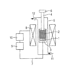
[Fig. 1] Fig. 1 is a schematic view illustrating an
example of an apparatus for use in the invention for measuring
thermal plasticity while maintaining a sample and a through-
hole material having through-holes from top to bottom surfaces
in a constant volume.
[Fig. 2] Fig. 2 is a schematic view illustrating an
example of an apparatus for use in the invention for measuring
thermal plasticity while applying a constant load onto a
CA 2962032 2017-03-22
- 25 -
sample and a through-hole material.
[Fig. 3] Fig. 3 is a schematic view illustrating a
through-hole material with circular through-holes as an
example of the through-hole materials for use in the invention.
[Fig. 4] Fig. 4 is a schematic view Illustrating a
spherical particle-packed layer as an example of the through-
hole materials for use in the Invention.
[Fig. 5] Fig. 5 is a schematic view illustrating a
cylinder-packed layer as an example of the through-hole
materials for use in the invention.
[Fig. 6] Fig. 6 is a graph showing results of the
measurement of the permeation distance of thermally plastic
coals in EXAMPLE 1.
[Fig. 7] Fig. 7 is a graph showing results of the
measurement of the permeation distance of thermally plastic
coals in EXAMPLE 2.
[Fig. 8] Fig. 8 is a graph showing a relationship between
the measured permeation distance and the weighted-average
permeation distance of thermally plastic coal blends in
EXAMPLE 3.
[Fig. 9] Fig. 9 is a graph showing a relationship between
the weighted-average permeation distance (measured by heating
under a constant load) of a coal with a logarithmic value of
Gieseler maximum fluidity of logMF ?_ 3.0 that is added to a
coal blend, and the drum strength measured in EXAMPLE 4.
CA 2962032 2017-03-22
- 26 -
[Fig. 101 Fig. 10 is a graph showing a relationship
between the weighted-average permeation distance (measured by
heating in a constant volume) of a coal with a logarithmic
value of Gieseler maximum fluidity of logMF 3.0 that
is added
to a coal blend, and the drum strength measured in EXAMPLE 4.
[Fig. 11] Fig. 11 is a picture showing a structure of coke
obtained by carbonization of a coal blend A that contained
coal A having a suitable permeation distance.
[Fig. 12] Fig. 12 is a picture showing a structure of coke
obtained by carbonization of a coal blend F that contained
coal F having an excessively large permeation distance.
[Description of Embodiments]
[0031]
Exemplary apparatuses used in the invention to measure
thermal plasticity are illustrated In Figs. 1 and 2. The
apparatus illustrated in Fig. 1 is dedicated to heating a
sample of a coal or a caking additive while maintaining the
sample and a material having through-holes from top to bottom
surfaces in a constant volume. The apparatus illustrated in
Fig. 2 is dedicated to heating a sample of a coal or a caking
additive while applying a constant load onto the sample and a
through-hole material. A coal or a caking additive is packed
at a lower part of a vessel 3 to give a sample 1. A through-
hole material 2 is arranged on top of the sample 1. The sample
CA 2962032 2017-03-22
- 27 -
1 is heated to or above a range of temperatures at which the
sample becomes softened and molten, so as to cause the sample
to permeate into the through-hole material 2. This permeation
distance is measured. The above heating is performed in an
inert gas atmosphere. Here, the term "inert gas" refers to a
gas that does not react with coal in the measurement
temperature range. The typical gases include argon gas, helium
gas and nitrogen gas.
[0032]
In the case where the sample 1 is heated while maintaining
the sample 1 and the through-hole material 2 in a constant
volume, the pressure during the permeation of the sample can
be measured via the through-hole material 2. As illustrated in
Fig. 1, a pressure detection rod 4 is arranged on the upper
surface of the through-hole material 2, and a load cell 6 is
placed in contact with the upper end of the pressure detection
rod 4 to measure the pressure. In order to maintain a constant
volume, the load cell 6 is fixed so as not to move in a
vertical direction. Before starting heating, the through-hole
material 2, the pressure detection rod 4 and the load cell 6
are brought into close contact with respect to the sample
packed in the vessel 3 so as to make sure that there are no
gaps between any of these members. In the case where the
through-hole material 2 is a particle-packed layer, the
pressure detection rod 4 can be buried into the particle-
CA 2962032 2017-03-22
- 28 -
packed layer. Thus, it is desirable that a plate be inserted
between the through-hole material 2 and the pressure detection
rod 4.
[0033]
When the sample 1 is heated while applying a constant load
onto the sample 1 and the through-hole material 2, the sample
1 is allowed to be swollen or contracted so as to move the
through-hole material 2 in a vertical direction. Thus, the
swelling coefficient during sample permeation can be measured
via the through-hole material 2. For this purpose, as
illustrated in Fig. 2, a swelling coefficient detection rod 13
may be arranged on the upper surface of the through-hole
material 2, a loading weight 14 may be placed onto the upper
end of the swelling coefficient detection rod 13, and a
displacement meter 15 may be arranged above the unit to
measure the swelling coefficient. The displacement meter 15
may be one capable of measuring the swelling coefficient in a
range in which the sample can be swollen (-100% to 300%).
Because the inside of the heating system needs to be
maintained in an inert gas atmosphere, a non-contact type
displacement meter is suitable, and an optical displacement
meter is desirably used. The inert gas atmosphere is
preferably a nitrogen atmosphere. In the case where the
through-hole material 2 is a particle-packed layer, the
swelling coefficient detection rod 13 can be buried into the
CA 2962032 2017-03-22
- 29 -
particle-packed layer. Thus, it is desirable that a plate be
inserted between the through-hole material 2 and the swelling
coefficient detection rod 13. The load is preferably applied
uniformly onto the upper surface of the through-hole material
arranged on the upper surface of the sample. It is desired
that a pressure of 5 to 80 kPa, preferably 15 to 55 kPa, and
most preferably 25 to 50 kPa be applied onto the area of the
upper surface of the through-hole material. This pressure is
preferably set based on the swelling pressure of a thermally
plastic layer in a coke oven. The present inventors studied
the reproducibility of measurement results and the power for
the detection of brand differences with respect to various
kinds of coals. As a result, the present inventors have found
that a pressure that is slightly higher than the swelling
pressure in an oven, in detail a pressure of about 25 to 50
kPa is most preferable as a measurement condition.
[0034]
Desirably, the heating means is of a type capable of
heating the sample at a predetermined temperature increase
rate while measuring the temperature of the sample. Specific
examples include an electric furnace, an external heating
system that is a combination of a conductive vessel and high-
frequency induction, and an internal heating system such as
microwaves. In the case where an internal heating system is
adopted, a design needs to be devised which allows the inside
CA 2962032 2017-03-22
- 30 -
temperature of the sample to become uniform. For example, it
is preferable to design a remedy which increases thermal
insulation properties of the vessel.
[0035]
In order to simulate thermally plastic behaviors of coals
and caking additives in a coke oven, the heating rate needs to
correspond to a heating rate for the coal in a coke oven. The
heating rate for coal around the softening and melting
temperatures in a coke oven is generally 2 to 10 C/min,
although variable depending on a location inside the oven and
operation conditions, and is desirably 2 to 4 C/min, and most
desirably about 3 C/min in terms of average heating rate. In
the case of low-fluidity coals such as non-coking coals and
slightly coking coals, however, heating at 3 C/min results in
a small permeation distance and small swelling which can be
difficult to detect. It is generally known that coal is
improved in fluidity according to a Gieseler plastometer by
being rapidly heated (see, for example, Non Patent Literature
3). Thus, in the case of a coal with a permeation distance of,
for example, 1 mm or less, the measurement may be performed at
an increased heating rate of 10 to 1000 C/min in order to
enhance detection sensitivity.
[0036]
Since the measurement is aimed at evaluating thermal
plasticity of coals and caking additives, heating may be
CA 2962032 2017-03-22
- 31 -
performed to such an extent that the temperature is increased
to softening and melting temperatures of coals and caking
additives. In view of the softening and melting temperatures
of coals and caking additives for coke production, heating may
be performed at a predetermined heating rate from 0 C (room
temperature) to 550 C, and preferably from 300 to 550 C that
is a range of temperatures at which coal becomes softened and
molten.
[0037]
The through-hole material is desirably one whose
permeability coefficient can be measured or calculated
beforehand. Exemplary configurations of the materials include
integral materials having through-holes, and particle-packed
layers. Examples of the integral materials having through-
holes include materials having circular through-holes 16 as
illustrated in Fig. 3, materials having rectangular through-
holes, and materials having irregular through-holes. The
particle-packed layers are largely classified into spherical
particle-packed layers and non-spherical particle-packed
layers. Examples of the spherical particle-packed layers
include layers formed of packed particles 17 such as beads as
illustrated in Fig. 4. Examples of the non-spherical particle-
packed layers include layers of irregular particles and layers
formed of packed cylinders 18 as illustrated in Fig. 5. In
order to ensure the reproducibility of the measurement, the
CA 2962032 2017-03-22
- 32 -
permeability coefficient is desirably as uniform as possible
throughout the material. For simple measurement, it is desired
that the material permit easy calculation of its permeability
coefficient. Thus, a spherical particle-packed layer is
particularly desired for use as the through-hole material in
the present invention. The substance which forms the through-
hole material is not particularly specified as long as it is
not substantially deformed at or above the softening and
melting temperatures of coal, in detail until 600 C, and does
not react with coal. The height of the material is not
particularly limited as long as the material is high enough to
accept the permeation of coal melt. In the case where a coal
layer with a thickness of 5 to 20 mm is heated, the height of
the through-hole material is appropriately about 20 to 100 mm.
[0038]
It is necessary that the permeability coefficient of the
through-hole material be set by assuming the permeability
coefficient of large defects present in a coke layer. The
present inventors studied a particularly preferred
permeability coefficient in the invention while considering
constituent factors of such large defects and assuming the
sizes thereof. As a result, the present inventors have found
that a permeability coefficient of 1 x 10⁸ to 2 x 10⁹ m-2 is
most suitable. This permeability coefficient is derived based
on the Darcy's law represented by Equation (1) below:
CA 2962032 2017-03-22
- 33 -
AP/L = Ku -- (1)
wherein AP is the pressure loss [Pa] inside the through-
hole material, L is the height [m] of the through-hole
material, K is the permeability coefficient [m-2], is the
viscosity [Pas] of the fluid, and u is the velocity [m/s] of
the fluid. For example, in the case where a layer of glass
beads with a uniform particle diameter is used as the through-
hole material, it is desired to select glass beads with a
diameter of about 0.2 mm to 3.5 mm, most desirably 2 mm, in
order to achieve the aforementioned suitable permeability
coefficient.
[0039]
Coals and caking additives for measurement samples are
crushed beforehand and are packed with a predetermined packing
density and a predetermined layer thickness. The crushed
particle size may be similar to a particle size of coal
charged into a coke oven (particles with a particle diameter
of not more than 3 mm representing about 70 to 80 mass%
relative to the total). Alternatively, the sample material is
preferably crushed such that particles with a particle
diameter of not more than 3 mm represent not less than 70
mass%. In view of the fact that the measurement is made with a
small apparatus, it is particularly preferable that the whole
of the crushed material has a particle diameter of not more
than 2 mm. The crushed material may be packed with a density
CA 2962032 2017-03-22
- 34 -
of 0.7 to 0.9 g/cm3 in accordance with a possible packing
density in a coke oven. Based on the results of studies on
reproducibility and detection power, the present inventors
have found that a packing density of 0.8 g/cm3 is preferable.
Based on the thickness of a thermally plastic layer in a coke
oven, the thickness of the packed layer may be 5 to 20 mm.
Studies on reproducibility and detection power made by the
present inventors have revealed that a layer thickness of 10
mm is preferable.
[0040]
It is essentially desired that the permeation distance of
a thermally plastic coal or a thermally plastic caking
additive be measurable constantly and continuously during
heating. However, constant measurement is difficult because of,
for example, the influences of tar generated from the sample.
Swelling and permeation of coal by heating are irreversible
phenomena. Thus, once coal has been swollen or permeated, the
shape thereof is substantially maintained even if the coal is
cooled. Based on this fact, the measurement may be performed
in such a manner that after the permeation of a coal melt has
terminated, the entirety of the vessel is cooled and the
extent to which the permeation has occurred during heating is
determined by measuring the permeation distance after cooling.
For example, the through-hole material may be removed from the
cooled vessel and the distance may be directly measured with a
CA 2962032 2017-03-22
- 35 -
vernier caliper or a ruler. In the case where the through-hole
material is particles, the thermal plastic that has permeated
into interparticle voids bonds the particle layer over the
distance of permeation. Thus, provided that a relationship
between the mass and the height of the particle-packed layer
has been measured beforehand, the permeation distance may be
calculated by measuring the mass of particles that are not
bonded together after the completion of the permeation, and
subtracting the measured mass from the initial mass to give
the mass of the bonded particles.
[0041]
Equation (1) described above includes the term of
viscosity ( ). Thus, the term of viscosity of the thermal
plastic that has permeated into the through-hole material can
be derived from the parameters measured according to the
invention. For example, in the case where the sample is heated
while the sample and the through-hole material are maintained
in a constant volume, AP corresponds to the pressure during
permeation, L to the permeation distance and u to the
permeation velocity, whereby the viscosity term can be derived
by substituting the above parameters into Equation (1).
Alternatively, in the case where the sample is heated while a
constant load is applied onto the sample and the through-hole
material, AP corresponds to the pressure of the applied load,
L to the permeation distance and u to the permeation velocity,
CA 2962032 2017-03-22
- 36 -
whereby the viscosity can be similarly derived by substituting
the above parameters into Equation (1).
[0042]
As demonstrated above, thermal plasticity of coals and
caking additives are evaluated by measuring the permeation
distance, the pressure or the swelling coefficient of
thermally plastic coals and thermally plastic caking additives.
Here, the phrase "thermal plasticity of a sample (a coal or a
caking additive) are evaluated" in the invention means that at
least the permeation distance, the pressure and the swelling
coefficient are measured and, based on the measured values,
indicators for quantitatively evaluating behaviors of coal
melt as well as consequent phenomena (for example, properties
of produced coke, pushing resistance of coke) are obtained.
The measured values of the permeation distance, the pressure
and the swelling coefficient may be used in combination with
other property values (for example, MF). Alternatively, one or
more selected from the permeation distance, the pressure and
the swelling coefficient alone may be used. In the latter case,
the evaluation of thermal plasticity is regarded as being made
when the measured values of the permeation distance, the
pressure and the swelling coefficient are obtained. That is,
measuring the permeation distance, the pressure and the
swelling coefficient has substantially the same meaning as
evaluating thermal plasticity. Further, the permeation
CA 2962032 2017-03-22
- 37 -
distance, the pressure and the swelling coefficient may be
used as parameters in the estimation of coke strength, whereby
it becomes possible to manufacture coke having desired
strength by blending coals of a number of brands. The most
common indicator of coke strength is drum strength at normal
temperature. In addition to drum strength, other coke
properties such as CSR (coke strength after reaction)
(strength after CO2 reaction), tensile strength and
microstrength may be estimated based on the above parameters,
whereby it becomes possible to produce coke having desired
strength by blending coals of a number of brands.
[0043]
In a conventional coal blending theory for estimating coke
strength, coke strength is thought to be determined mainly by
an mean maximum vitrinite reflectance (Ro) and a logarithmic
value of Gieseler maximum fluidity (NF) (logMF) of coal (see,
for example, Non Patent Literature 4). Gieseler fluidity is an
indicator of fluidity exhibited when the coal is thermally
plastic, and is represented in terms of the rotational speed
of a stirring rod of a Gieseler plastometer, namely, the
degree of rotations per 1 minute in ddpm (dial division per
minute) unit. The coal property used is maximum fluidity (MF).
Alternatively, common logarithm of ddpm is sometimes used.
Because the permeation distance according to the invention is
thought to be a parameter that indicates fluidity under
CA 2962032 2017-03-22
- 38 -
conditions simulating thermally plastic behaviors in a coke
oven, this parameter will be superior to a logarithmic value
of Gieseler maximum fluidity logMF in estimating coke
properties or coke cake structures.
[0044]
This superiority of the permeation distance is expectable
in principle based on the fact that the measurement method
simulates an environment in a coke oven, and has been
confirmed by the results of a study that examined the
influences of the permeation distance on coke strength. In
fact, it has been found by the inventive evaluation method
that coals with similar logMF have different permeation
distances depending on brands. It has been further confirmed
that coke strength is affected differently when coals having
different permeation distances are blended and produced into
coke. In detail, as will be demonstrated in EXAMPLES later, a
relation is such that coke strength is decreased after the
value of permeation distance exceeds a certain threshold. The
reasons for this are considered as follows.
[0045]
When coals having a long permeation distance are blended,
the proportion of coals that exhibit sufficient melting
properties during carbonization is considered to be high. It
is, however, assumed that coals having an excessively long
permeation distance permeate between surrounding coal
CA 2962032 2017-03-22
- 39 -
particles to such a marked extent that regions where these
coal particles have been present are left as large cavities,
leading to defects. Although a conventional concept based on
Gieseler maximum fluidity has anticipated the possibility of a
decrease in coke strength in the case of a coal blend
exhibiting too high fluidity (see, for example, Non Patent
Literature 4), it has yet been impossible to clarify behaviors
of individual brands having high fluidity. One of the reasons
for this is probably because the conventional Gieseler
fluidity measurement is incapable of an accurate measurement
of properties at high fluidity due to the aforementioned
Weissenberg effect. The inventive measurement method has
enabled more accurate evaluation of properties of melts,
particularly at high fluidity. Thus, the present invention has
made significant advances by making it possible to clarify
differences in properties between thermal plastics that have
been difficult to distinguish by conventional methods, as well
as by allowing for better evaluation of a relationship between
thermally plastic behaviors and coke structures.
[0046]
The present inventors have established suitable
measurement conditions in the inventive method, and have
completed a method for producing high-strength coke using the
measurement results.
CA 2962032 2017-03-22
- 40 -
[EXAMPLES]
[EXAMPLE 1]
[0047]
There will be described measurement examples of constant-
volume heating for samples of coals and caking additives in
combination with a material having through-holes from top to
bottom surfaces. The permeation distance and the pressure
during permeation were measured using 17 types of coals and 4
types of caking additives (coals A to Q, caking additives R to
U) as samples. Table 1 describes properties (mean maximum
reflectance: Ro, logarithmic value of Gieseler maximum
fluidity: logMF, volatile matter content: VM, ash content:
Ash) of the coals and the caking additives used. The
measurement of the fluidity of the caking additives used
herein by a Gieseler plastometer method resulted in common
logarithmic values of all of these Gieseler maximum fluidities
(logMF) being 4.8, which was the detection limit.
[0048]
[Table 1]
log ME VM Ash
Coal Ro
[log ddpm] [mass%] [mass%]
Coal A 0.66 3.55 43.2 5.8
Coal B 0.67 1.00 36.6 9.0
Coal C 0.72 3.61 40.8 9.0
Coal D 0.73 ____________________ 2.29 36.2 8.8
Coal E 0.75 2.32 38.1 9.7
Coal F 0.79 3.96 37.2 7.9
Coal G 0.91 3.59 33.0 7.9
CA 2962032 2017-03-22
- 41 -
Coal H 0.99 2.84 29.1 8.6
Coal I 1.00 1.71 , 25.8 9.6
Coal J 1.00 2.20 27.7 10.4
Coal K 1.03 2.97 28.2 9.6
Coal L 1.30 1.34 21.0 9.4
Coal M 1.31 1.26 20.4 7.3
Coal N 1.38 2.49 20.9 10.9
Coal 0 1.44 2.03 21.1 9.3
Coal P 1.54 0.00 16.6 8.3
Coal Q 1.62 0.70 18.8 9.6
Caking additive R Not less than 4.8 Less than 1
Caking additive S Not less than 4.8 Less than 1
Caking additive T Not less than 4.8 Less than 1
Caking additive U Not less than 4.8 Less than 1
[0049]
With use of an apparatus similar to that illustrated in
Fig. 1, the permeation distance and the pressure during
permeation were measured. The heating system was a high-
frequency induction heating system. That is, a heating element
8 and a vessel 3 in Fig. 1 were an induction heating coil and
a dielectric graphite vessel. The vessel 3 was 18 mm in
diameter and 37 mm in height. Glass beads having a diameter of
2 mm were used as a through-hole material 2. The vessel was
charged with 2.04 g of a sample that had been crushed to a
particle diameter of not more than 2 mm and had been vacuum
dried at room temperature. A weight weighing 200 g was dropped
from above the sample five times with a fall distance of 20 mm,
thereby packing the sample. (At this time, the thickness of
the sample layer was 10 mm.) Next, the glass beads with a 2 mm
diameter were arranged on the packed layer of the sample 1 so
CA 2962032 2017-03-22
- 42 -
as to achieve a thickness of 25 mm, thereby preparing a glass
bead-packed layer as the through-hole material 2. On the glass
bead-packed layer, a sillimanite disk with a diameter of 17 mm
and a thickness of 5 mm was arranged, and a quartz rod as a
pressure detection rod 4 was further arranged thereon. With
use of nitrogen gas as an inert gas, the sample was heated
from room temperature to 550 C at a heating rate of 3 C/min.
During the heating, the pressure transmitted via the pressure
detection rod 4 was measured with a load cell 6. After the
completion of the heating, cooling was performed in a nitrogen
atmosphere. The beads that had not adhered to the thermal
plastic were collected from the cooled vessel 3, and the mass
thereof was measured.
[0050]
The permeation distance was determined on the basis of the
packing height of the bead layer that had adhered together. A
relationship had been obtained beforehand between the packing
height and the mass of the glass bead-packed layer, whereby it
became possible that from the mass of beads adhering together
with the thermal plastic, the packing height of such glass
beads was derived as shown in Equation (2) below. The
permeation distance was derived from Equation (2).
L = (G - M) x H ===(2)
wherein L is the permeation distance [mm], G the mass [g]
of the packed glass beads, M the mass [g] of the beads that
CA 2962032 2017-03-22
- 43 -
had not adhered together with the thermal plastic, and H the
height of the packed layer per 1 g of the glass beads packed
into this experimental apparatus [mm/g].
[0051]
For the caking additives, the permeation distance was
measured by using a sample vessel with the same diameter as
described above but with a height of 100 mm, and by arranging
a glass bead-packed layer with a thickness of 80 mm onto the
sample. This configuration was adopted because the permeation
distance of caking additives was large. Separately, tests were
carried out in which a coal was packed with a constant sample
layer thickness while changing the height of the vessel and
the thickness of the glass bead-packed layer. The measured
values of the permeation distance were identical as long as
the thickness of the glass bead-packed layer was greater than
the permeation distance.
[0052]
Table 2 describes the measurement results of the
permeation distance and the maximum pressure during permeation.
Fig. 6 shows a relationship between the measurement results of
the permeation distance and the logarithmic values of Gieseler
maximum fluidity (logMF). (Plotting excluded values of caking
additives whose ME value was not measured accurately.)
[0053]
CA 2962032 2017-03-22
- 44 -
[Table 2]
Permeation distance Maximum pressure
Coal
[mm] [kPa]
Coal A 6.9 25
Coal B 0.2 16
Coal C 13.3 15
Coal D 2.4 6
Coal E 5.5 25
Coal F 19.0 18
Coal G 14.9 23
Coal H 6.8 7
Coall 1.9 10
Coal J 3.2 16
Coal K 11.5 21
Coal L 0.3 5
Coal M 0.9 0
Coal N 4.0 20
Coal 0 8.1 68
Coal P 0.0 0
Coal Q 0.8 6
Caking additive R 58.0 2
Caking additive S 48.0 2
Caking additive T 50.0 4
Caking additive U 65.0 1
[0054]
From Fig. 6, the permeation distance showed a certain
extent of correlation with logMF, though a number of brands
deviated from the correlation. Further, the measurement
results for the caking additives in Table 2 have shown that
the differences in properties of caking additives were
successfully observed. Such discrimination has been impossible
with conventional methods. In a measurement in which a sample
and a through-hole material are heated in a constant volume,
CA 2962032 2017-03-22
- 45 -
the factors that will affect the permeation distance are, as
shown in Equation (1), the viscosity t of the sample and the
swelling pressure AP of the sample, which vary from sample to
sample. Thus, the permeation distances and the pressures
measured while heating the samples of coals and caking
additives in combination with the through-hole material in a
constant volume are considered to reflect the state of the
melt in a coke oven. Because the melt condition and the
pressure of thermally plastic coals and thermally plastic
caking additives are assumed to affect the structure of coke
after carbonization, it can be said that such parameters are
particularly effective in the estimation of coke strength.
[0055]
Further, because the pressure exerted during the
permeation of the sample is the result of pressure measurement
carried out in a measurement environment simulating swelling
behaviors in a coke oven, it can be said that this parameter
is effectively used in order to estimate the pressure applied
to the wall of a coke oven during the carbonization of coal in
a coke oven.
[EXAMPLE 2]
[0056]
Measurement examples will be described in which coals and
caking additives as samples were heated while applying a
constant load to the sample and a material having through-
CA 2962032 2017-03-22
- 46 -
holes from top to bottom surfaces. The permeation distance and
the swelling coefficient during permeation were measured with
respect to the same coals and caking additives as in EXAMPLE 1,
namely, 17 types of coals and 4 types of caking additives
(coals A to Q, caking additives R to U) shown in Table 1. With
use of an apparatus similar to that illustrated in Fig. 2, the
permeation distance and the swelling coefficient during
permeation were measured. The heating system was a high-
frequency induction heating system. That is, a heating element
8 and a vessel 3 in Fig. 2 were an induction heating coil and
a dielectric graphite vessel. The vessel 3 was 18 mm in
diameter and 37 mm in height. Glass beads having a diameter of
2 mm were used as a through-hole material. The vessel 3 was
charged with 2.04 g of a sample that had been crushed to a
particle diameter of not more than 2 mm and had been vacuum
dried at room temperature. A weight weighing 200 g was dropped
from above the sample five times with a fall distance of 20 mm,
thereby packing the sample 1. Next, the glass beads with a 2
mm diameter were arranged on the packed layer of the sample 1
so as to achieve a thickness of 25 mm, thereby preparing a
glass bead-packed layer as the through-hole material 2. On the
glass bead-packed layer, a sillimanite disk with a diameter of
17 mm and a thickness of 5 mm was arranged, and a quartz rod
as a swelling coefficient detection rod 13 was further
arranged thereon. Furthermore, a weight 14 weighing 1.3 kg was
CA 2962032 2017-03-22
- 47 -
placed on top of the quartz rod. As a result, the pressure
applied onto the sillimanite disk was 50 kPa. With use of
nitrogen gas as an inert gas, the sample was heated to 550 C
at a heating rate of 3 C/min. During the heating, a
displacement was measured with a laser displacement meter, and
the swelling coefficient was calculated from the height with
which the sample had been packed. After the completion of the
heating, cooling was performed in a nitrogen atmosphere. The
beads that had not adhered to the thermal plastic were
collected from the cooled vessel, and the mass thereof was
measured. The permeation distance was derived from Equation
(2).
[0057]
In the measurement of the permeation distance of the
caking additives in this example too, tests were carried out
while using a larger vessel and increasing the thickness of
the glass bead-packed layer similarly in EXAMPLE 1. It was
confirmed that the thickness of the glass bead-packed layer
did not affect the measured values of the permeation distance
under the conditions of EXAMPLE 2.
[0058]
Table 3 describes the measurement results of the
permeation distance and the final swelling coefficient. Fig. 7
shows a relationship between the measurement results of the
permeation distance and the logarithmic values of Gieseler
CA 2962032 2017-03-22
- 48 -
maximum fluidity (logMF). (Plotting excluded values of caking
additives whose MF value was not measured accurately.)
[0059]
[Table 3]
Permeation distance Final swelling coefficient
Coal
[mm] [0,10]
Coal A 8.2 -9
Coal B 3.3 -9
Coal C 14.9 -41
Coal D 8.1 -8
Coal E 8.0 -9
Coal F 21.3 -55
Coal G 19.0 -48
Coal H 6.3 -9
Coal I 2.5 -16
Coal J 4.8 -16
Coal K 12.1 -16
Coal L 1.3 -2
Coal M 0.9 -9
Coal N 8.7 -15
Coal 0 7.8 4
Coal P 1.2 0
Coal Q 3.0 11
Caking additive R 65.0 -82
Caking additive S 52.0 -75
Caking additive T 55.0 -81
Caking additive U 70.0 -85
[0060]
From Fig. 7, the permeation distance measured in this
example is shown to have a certain extent of correlation with
logMF. However, it is also found that some brands exhibited
different permeation distances even though their logMF values
were similar. In particular, this tendency was seen in a
CA 2962032 2017-03-22
- 49 -
higher logMF region. In view of the fact that the error of the
measurement of the permeation distance with this apparatus was
found to be 0.6 in terms of standard error by repeating a test
three times under the same conditions, a significant
difference in permeation distance was shown with respect to
the coal H and the coal K having substantially equal logMF.
Based on only the relation represented by Equation (1), it can
be assumed that brands with the same logMF will have a similar
viscosity in a molten state, and thus the permeation
distances will be identical. The reasons for this assumption
are because AP and K are constant in this measurement
irrespective of the samples to be analyzed, as well as because
logMF of a coal is substantially correlated with temperatures
at which the coal exhibits melting properties (herein, such
temperatures correspond to melting time), and therefore the
term u can be regarded to be substantially constant. During
carbonization of coal, however, gas generation and swelling
phenomena are observed simultaneously with melting of the coal
due to driving off of volatile matters. Thus, the values of
the permeation distance obtained in this measurement are
assumed to reflect the combined influences of the permeation
of the melt into the bead-packed layer and the gas generation
from the melt in the bead layer. Because these values are
assumed to be factors that determine the structure of coke
after carbonization, it can be said that such parameters are
CA 2962032 2017-03-22
- 50 -
particularly effective in the estimation of coke strength.
[0061]
Further, the final swelling coefficients described in
Table 3 are swelling coefficient values at 550 C. Because the
results in Table 3 come from the measurement of swelling
coefficient in a measurement environment simulating swelling
behaviors in a coke oven, it can be said that the data are
effective for estimating coke strength as well as for
estimating a gap between the wall of a coke oven and a mass of
coke.
[EXAMPLE 3]
[0062]
Whether there was an additivity of the permeation distance
was investigated according to the same measurement method as
in EXAMPLE 2.
[0063]
Two brands were selected from 4 types of coals (coals V to
Y) and were blended at various blend ratios to give coal
blends as samples. The samples were subjected to the
measurement of the permeation distance. Table 4 describes the
coals used and properties (Ro, logMF, VM, Ash) of the coal
blends. Here, the properties of the coal blends are weighted-
average values of properties of individual coals averaged
according to the blending proportions. The measurement results
of the permeation distance are also described in Table 4. Fig.
. CA 2962032 2017-03-22
- 51 -
8 shows a relationship between the weighted-average permeation
distances and the measured permeation distances of the coal
blends.
[0064]
CA 2962032 2017-03-22
- 52 -
[Table 4]
Blend ratio (%)
Permeation
logMF VM Ash
Coal Coal Coal Coal Coal Ro distance
[log ddpm] [%] [io]
V W X Y [mm]
Coal V 100 0 0 0 0.80 4.00 35.9 8.9 21.5
Coal W 0 100 0 0 1.00 3.08 27.7 10.4 12.9
Coal X 0 0 100 0 0.72 2.40 35.9 9.1 9.4
Coal Y 0 0 0 100 1.29 0.48 20.8 7.6 2.5
Coal blend
75 25 0 0 0.85 3.77 33.9 9.3 19.1
VVV1
Coal blend
50 50 0 0 0.90 3.54 31.8 9.7 16.4
VVV2
Coal blend
25 75 0 0 0.95 3.31 29.8 10.0 13.6
VVV3
Coal blend
75 0 25 0 0.78 3.60 35.9 9.0 18.2
VX1
Coal blend
50 0 50 0 0.76 3.20 35.9 9.0 14.8
VX2
Coal blend
25 0 75 0 0.74 2.80 35.9 9.1 12.3
VX3
Coal blend
50 0 0 50 1.05 2.24 28.4 8.3 8.7
VY1
Coal blend
0 75 25 0 0.93 2.91 29.8 10.1 10.9
WX1
Coal blend
0 50 50 0 0.86 2.74 31.8 9.8 11.1
WX2
Coal blend
0 25 75 0 0.79 2.57 33.9 9.4 9.5
WX3
Coal blend
0 50 0 50 1.15 1.78 24.3 9.0 6.5
VVY1
Coal blend
0 0 50 50 1.01 1.44 28.4 8.4 5.2
XY1
[0065]
From Fig. 8, it has been shown that there is a very good
additivity for the permeation distances measured in this
example. Accordingly, the permeation distance value of a coal
CA 2962032 2017-03-22
- 53 -
blend formed of two or more types of coals may be determined
by actually measuring the permeation distance of a sample of
the coal blend, or by previously measuring the permeation
distances of individual coals to be blended and estimating the
permeation distance by calculating the weighted-average value.
[0066]
With regard to coals used for coal blends, various
qualities and grades are usually measured beforehand with
respect to each brand, and the obtained data are used in the
blending of coals. Accordingly, it is practically preferable
that the permeation distance be measured beforehand with
respect to each lot of brand, thereby enabling smooth
calculation of the permeation distance of a coal blend.
[EXAMPLE 4]
[0067]
The values of thermal plasticity of coals obtained in the
present invention were applied to the estimation of coke
strength and the effectiveness thereof was examined.
[0068]
As described above, the permeation distance according to
the invention is considered to be a parameter superior to a
logarithmic value of Gieseler maximum fluidity logMF in the
estimation of coke properties and coke cake structures. Thus,
a carbonization test and a test of coke strength after
carbonization were carried out as outlined below in order to
CA 2962032 2017-03-22
- 54 -
examine how coke strength would be affected when coke were
produced using coals having substantially the same logMF and
different permeation distances.
[0069]
Referring to Table 1 used in EXAMPLES 1 and 2, the coal A,
the coal F and the coal G (each with logMF of not less than
3.5) were selected as "similar MF coals". Each of these coals
was blended at 20 mass% together with various coals as the
balance such that the weighted-average Ro values and the
weighted-average logMF values of the coal blends as a whole
would be the same, thereby preparing coal blends (coal blends
A, F and G). The coal A, the coal F and the coal G are such
types of coals which have a high ME among coals used in coke
producing and are frequently used in order to improve the
adhesiveness of coal particles in coke producing. Further,
coal blends including a number of brands with logMF 3.0 at
the same time (coal blend AF, coal blend FG and coal blend
FGK) were prepared in order to test properties of coal blends
containing such high-MF coals. These coal blends were prepared
such that the average qualities and grades would be Ro - 0.99
to 1.05 and logMF = 2.0 to 2.3. Table 5 describes the brands
and the proportions of the coals used in the respective coal
blends, the weighted-average constant-volume permeation
distances (calculated from the values in Table 2) and the
weighted-average constant-pressure permeation distances
CA 2962032 2017-03-22
- 55 -
(calculated from the values in Table 3) of the coals with
logMF 3.0 in the coal blends, and the strength of the
produced coke.
[0070]
CA 2962032 2017-03-22
- 56 -
[Table 5]
Coal Blend ratio
Coal blend Coal blend Coal blend Coal blend Coal blend Coal blend
A F G AF FG FGK
[mass%] [mass%] [mass%] [mass%] [mass%] [mass%]
Coal A 20 0 0 10 0 0
Coal B 11 12 19 11 0 0
Coal D 0 0 0 0 17 20
Coal F 0 20 0 10 11 11
Coal G 0 0 20 0 17 14
Coal H 18 20 3 20 20 0
Coal I 19 20 18 20 0 0
Coal J 8 10 20 9 0 0
Coal K 0 0 0 0 0 20
Coal L 0 0 0 0 22 23
Coal M 9 6 91 7 0 0
1
Coal N 10 8 6' 8 0 0
Coal P 0 0 0; 0 13 12
Coal Q 5 4 5 5 0 0
Average volume- 1
constant permeation
6.9 19.0 14.9 13.0 16.5 14.4
distance (mm) of coal
with logMF 3.0
Average pressure-
constant permeation
8.2 21.3 19.0 14.7 19.9 16.5
distance (mm) of coal
with logMF 3.0
Coke strength
80.9 79.6 79.4 80.3 79.9 81.2
DI150/15 [-]
MSI (+65) [%] 54.4 52.1 52.3 54.4 52.8 54.2
CRI [%] - - - 29.7 29.5
CSR [A] - - - 55.4 59.5
[0071]
Each of the coals in Table 5 was used after being crushed
such that particles with a particle diameter of not more than
3 mm represented 100 mass% . Further, the water content was
CA 2962032 2017-03-22
- 57 -
adjusted such that the water content in the whole coal blend
would be 8 mass%. The coal blend weighing 16 kg was packed
into a carbonization can such that the bulk density would be
750 kg/m3, and a 10 kg weight was placed thereon. The coal
blend was then carbonized in an electric furnace at a furnace
wall temperature of 1050 C for 6 hours, removed from the
furnace, and cooled in a nitrogen atmosphere to give a coke.
The coke strength of the obtained coke was determined based on
a drum strength testing method in accordance with JIS K 2151,
in which the drum was rotated at 15 rpm and the mass
proportion of coke particles that had a particle diameter of
not less than 15 mm after 150 rotations was calculated. The
mass ratio thereof to the mass proportion before the rotations
was calculated to give a drum strength index DI 150/15.
Further, the results of measurements of CRI (CO2 reactivity),
CSR (strength after CO2 reaction, all measured in accordance
with an ISO 18894 method), and microstrength (MSI+65) are also
described.
[0072]
Fig. 9 shows a relationship between the weighted-average
value of the constant-pressure permeation distance of the coal
in each coal blend with a logarithmic value of Gieseler
maximum fluidity of logMF 3.0 (the permeation distance
measured in EXAMPLE 2 by heating the coal sample while
applying a constant load onto the coal sample and the through-
CA 2962032 2017-03-22
- 58 -
hole material), and the drum strength of the carbonized coke
from each coal blend. From the comparison of the strengths of
the coal blend A, the coal blend F and the coal blend G which
contained the coal A, the coal F and the coal G, respectively,
at 20 mass% as the similar MF coal, the drum strength was
shown to be higher as the permeation distance of the similar
MF coal was shorter. Further, the results of the drum
strengths of the coal blend A, the coal blend F and the coal
blend AF show that there is an additivity between the
permeation distance and the drum strength of the similar MF
coals. These results, in combination with the results of the
coal blend FG and the coal blend FGK, show that the coke
strength decreases when the weighted-average value of the
constant-pressure permeation distance of the coal in the coal
blend with a logarithmic value of Gieseler maximum fluidity of
logMF 3.0 exceeds 17 mm. Thus, the producing of high-
strength coke can be realized by regulating the weighted-
average value of the constant-pressure permeation distance of
the coal in the coal blend with a logarithmic value of
Gieseler maximum fluidity of logMF ?_ 3.0 to be not more than 17
mm.
[0073]
Next, Fig. 10 shows a relationship between the weighted-
average value of the constant-volume permeation distance of
the coal in each coal blend with a logarithmic value of
CA 2962032 2017-03-22
- 59 -
Gieseler maximum fluidity of logMF 3.0 (the permeation
distance measured in EXAMPLE 1 by heating the coal sample in
combination with the through-hole material in a constant
volume), and the drum strength of the carbonized coke from
each coal blend.
[0074]
A similar tendency, although slightly weaker than in Fig.
9, was confirmed also in Fig. 10. Thus, it has been shown that
the values of the permeation distance obtained in this
measurement affect coke strength in both cases in which such
values are determined by the constant-volume heating
measurement and by the constant-load heating measurement. It
has been determined that when the constant-volume permeation
distance is adopted as an indicator, the weighted-average
value of the constant-volume permeation distance of the coal
in the coal blend with a logarithmic value of Gieseler maximum
fluidity of logMF 3.0 is preferably regulated to be not more
than 15 mm. Because the measurement of the permeation distance
with respect to an identical coal affords different results
depending on the measurement conditions used, it is necessary
that coals be each evaluated under substantially identical
conditions. Here, the term "substantially identical" means
that the products of the sample layer thickness and the
packing density are within 20, the types of the through-hole
materials (for example, spherical particle-packed layers or
CA 2962032 2017-03-22
- 60 -
cylinder-packed layers) are the same but the diameters of the
spheres or the cylinders are within 20%, and the heating rates
are within -120%. The measurement conditions may be used
practically without any problems as long as the differences
are within the above ranges. By previously obtaining, based on
values measured under such conditions as defined above,
correlations as illustrated in Figs. 9 and 10 between the
permeation distance of a high-MF coal in a coal blend and the
strength of coke obtained by carbonization of the coal blend,
it becomes possible to determine the extent to which the
permeation distance of the high-ME coal should be adjusted in
order to obtain a desired coke strength. Further, CSR was
measured with respect to the coke produced from the coal blend
FG and the coal blend FGK. As a result, a similar tendency to
the JIS drum strength was observed, with CSR of the coke from
the coal blend FG being 55.4 (reactivity CRI = 29.7) and CSR
of the coke from the coal blend FGK being 59.5 (reactivity CRI
= 29.5). In general, it is known that when the reactivities
CRI of coke are similar, CSR shows a good correlation with JIS
drum strength. This tendency was confirmed also with the
samples in EXAMPLES. Similar tendencies to JIS drum strength
were also observed for microstrength and indirect tensile
strength.
[0075]
As demonstrated above, it has been revealed that the
CA 2962032 2017-03-22
- 61 -
permeation distance of a high-MF coal greatly affects coke
strength. In particular, the reason why the permeation
distance of a high-ME coal has marked effects is probably
because differences in permeation distance become larger as
coals have higher NE, as shown in Fig. 6 and Fig. 7. Low-MF
coals have limited differences in permeation distance among
brands, and thus it is probable that their permeation
distances did not exert significant influences. Further, it is
probable that the evaluation of thermal plasticity of high-ME
coals by a Gieseler plastometer method has been insufficient
due to the aforementioned Weissenberg effect and the presence
of measurable upper limit. The inventive method improves
defects possessed by conventional methods, and will make it
possible to obtain a new finding concerning the Influences of
thermal plasticity on coke strength.
[0076]
Next, the reasons why the permeation distance affected
coke strength were examined by observing with an optical
microscope the structure of coke obtained by carbonization of
the coal blend A which contained 20 mass% of the coal A whose
permeation distance was thought to be appropriate, as well as
the structure of coke obtained by carbonization of the coal
blend F which contained 20 mass% of the coal F whose
permeation distance was thought to be excessively long. Fig.
11 and Fig. 12 show pictures of the coal blend A and the coal
CA 2962032 2017-03-22
- 62 -
blend F, respectively, taken at 100x magnification.
[0077]
From the comparison between the pictures shown in Fig. 11
and Fig. 12, it has been shown that the coke from
carbonization of the coal blend F that contained the coal F
with an excessively long permeation distance had thinner pore
walls 20 and distorted large pores 21 as a result of linking
together of pores, compared to the coke from carbonization of
the coal blend A that contained the coal A with an appropriate
permeation distance. It has been reported that coke strength
becomes higher as pore walls are thicker and pores have a
higher circularity (see, for example, Non Patent Literature 5).
Accordingly, it has been confirmed that the permeation
distance of coal affects the formation of a coke structure
during carbonization and consequently affects the strength of
the coke.
[0078]
The results in EXAMPLES show that the permeation distance,
which is measured by heating the coal sample while applying a
constant load onto the coal sample and the through-hole
material or by heating the coal sample while maintaining the
sample and the through-hole material in a constant volume, is
a factor which affects the strength of coke produced from the
coal and which cannot be accounted for with conventional
factors, as well as show that the utilization of the
CA 2962032 2017-03-22
- 63 -
permeation distance in combination with other conventional
parameters in the estimation of coke strength will allow for
highly accurate estimation of strength. Further, it is now
apparent that the producing of high-strength coke is possible
by blending coals based on the permeation distances measured
under the preferred conditions.
[Reference Signs List]
[0079]
1 SAMPLE
2 THROUGH-HOLE MATERIAL HAVING THROUGH-HOLES FROM TOP TO
BOTTOM SURFACES
3 VESSEL
4 PRESSURE DETECTION ROD
SLEEVE
6 LOAD CELL
7 THERMOMETER
8 HEATING ELEMENT
9 TEMPERATURE DETECTOR
TEMPERATURE CONTROLLER
11 GAS INLET
12 GAS OUTLET
13 SWELLING COEFFICIENT DETECTION ROD
14 WEIGHT
DISPLACEMENT METER
16 CIRCULAR THROUGH-HOLE
CA 2962032 2017-03-22
,
- 64 -
17 PACKED PARTICLE
18 PACKED CYLINDER
20 PORE WALL
21 PORE