Note: Descriptions are shown in the official language in which they were submitted.
CA 02962046 2017-03-21
WO 2016/049028 PCT/US2015/051452
CATHETER SYSTEMS AND METHODS FOR RE-ENTRY
IN BODY VESSELS WITH CHRONIC TOTAL OCCLUSION
Inventor: David MAJERCAK
BACKGROUND
[0001] An interventional guide wire or other interventional device is
often used in
medical procedures that attempt to establish a pathway through a heavily
stenosed or
chronically occluded vessel. A chronically occluded vessel is referred to as
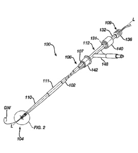
containing a
chronic total occlusion CTO. During these procedures, the guide wire or device
can
only be of clinical benefit to establish vessel patency if it is advanced
distally into the
vessel true lumen.
[0002] At times during the process of advancing the guide wire or device
through the
stenosed vessel or CTO, and beyond the control of the operator, the guide wire
or
device may inadvertently enter into the wall of the vessel itself, i.e. the
sub-intimal
plane or space, or dissection plane. Once in this sub-intimal plane, it
becomes difficult
to navigate the guide wire or device through the sub-intimal tissue to re-gain
access into
the vessel true lumen at points distal to the occlusion, i.e., a "re-entry"
into the vessel
lumen from the sub-intimal space but around the CTO. The layer of tissue that
separates the vessel true lumen from the sub-intimal plane is typically in the
range from
100 to 500 micrometers for vessels in the diameter range from 2 mm to 4 mm,
and
from 100 to 3000 microns, in the largest vessels of the body.
[0003] There exist a variety of catheters for re-entry around a CTO. One
is described
and shown in US 6,231,546. In the system of this US Patent, the re-entry
catheter
requires the operator to rotate a catheter shaft while observing a radiopaque
marker on
the catheter shaft to ensure that a side or lateral port is aimed at the true
lumen of the
blood vessel. Once the marker indicates the correct orientation of the lateral
port, a
cannula is extended through the lateral port in order to penetrate through the
intimal
layer of the blood vessel. It is believed that one drawback of this system is
the
requirement to rotate the catheter to the correct position while under
fluoroscopic
imaging otherwise an incorrect orientation of the cannula could cause internal
hemorrhaging of the blood vessel.
1
CA 02962046 2017-03-21
WO 2016/049028 PCT/US2015/051452
[0004] Another system is described and illustrated in US Patent
Application
Publication 2013/0072957. In this publication, a balloon is used to orient the
cannula
into the proper orientation for re-entry into the true vessel lumen. To
achieve this, the
catheter utilizes an asymmetrical catheter lumen for the cannula. It is
believed that this
system also suffers from a similar drawback in that the lateral port of the
cannula must
be oriented in the correct direction towards the true lumen while under
fluoroscopy.
This is to ensure that the cannula does not penetrate away from the true
lumen, which
could lead to internal hemorrhaging.
SUMMARY OF THE DISCLOSURE
[0005] Recognizing these shortcomings of the aforementioned prior art, I
have devised
a heretofore new device that overcome these shortcomings. In particular, I
have
devised a catheter system that includes a catheter handle, a catheter body, a
movable
catheter sheath, an inner catheter shaft, a cannula, and a guidewire. The
catheter handle
extends along a longitudinal axis from a first end to a second end. The handle
has a
hollow tubular portion extending through the handle, a fitting proximate the
first end, a
hemostatic fitting proximate the second end and a side port disposed between
the first
and second ends. The catheter body extends from the catheter handle along the
longitudinal axis from a proximal catheter end to a distal catheter end. The
catheter
body includes an articulation joint interposed between portions of the
catheter body
proximate the distal end. The movable catheter sheath has a portion surrounded
by an
internal surface of the catheter body and configured for movement along the
longitudinal axis with respect to the catheter body. The catheter sheath
extends through
the catheter handle. The inner catheter shaft has a portion surrounded by an
internal
surface of the movable catheter sheath, the inner catheter shaft having an
expandable
frame attached proximate and end of the inner catheter shaft. The inner
catheter shaft
includes a terminal end proximate the distal end, where the terminal end has a
plurality
of slots extending along the longitudinal axis to allow the expandable arms to
extend
through respective slots. The cannula has a portion surrounded by an internal
surface of
the inner shaft and disposed for movement with respect to the inner shaft, and
the
cannula is configured to extend to the handle. The guidewire has a portion
surrounded
by an internal surface of the cannula, the guidewire configured to extend
through the
cannula to the handle.
2
CA 02962046 2017-03-21
WO 2016/049028 PCT/US2015/051452
[0006] In yet another variation, I have devised an endovascular catheter
that includes
a catheter body, inner catheter shaft and a cannula. The catheter body extends
along
the longitudinal axis from a proximal catheter end to a distal catheter end.
The catheter
body includes an articulation joint interposed between portions of the
catheter body
proximate the distal end. The inner catheter shaft has a portion surrounded by
an
internal surface of the catheter body. The inner catheter shaft has an
expandable frame
attached proximate and end of the inner catheter shaft. The inner catheter
shaft
includes a terminal end proximate the distal end, the terminal end having a
plurality of
slots extending along the longitudinal axis to allow arm portions of the
expandable
frame to extend through respective slots. The cannula has a portion surrounded
by an
internal surface of the inner shaft and disposed for movement with respect to
the inner
shaft, the cannula configured to extend through the inner catheter shaft.
[0007] In yet a further variation, I have devised an inner catheter shaft
for use with a
catheter that includes a body and an expandable frame. The body extends along
a
longitudinal axis from a first end to a second end with a plurality of
openings extending
through a conical surface of the second end to define generally elliptical
through-slots
into the conical surface. The expandable frame has a plurality of arms
extending
through respective through slots to connect to a hub portion proximate the
second end.
The body includes a cannula opening extending through the first end to the
second end
to allow insertion of a cannula.
[0008] In yet another embodiment, I have devised a technique for re-entry
around a
chronic total occlusion of a blood vessel with a specially configured
catheter. The
catheter includes a catheter body extending along the longitudinal axis from a
proximal
catheter end to a distal catheter end. The catheter body includes an
articulation joint
interposed between portions of the catheter body proximate the distal end, an
inner
catheter shaft having a portion surrounded by an internal surface of the
catheter body,
the inner catheter shaft having an expandable frame attached proximate and end
of the
inner catheter shaft, the inner catheter shaft including a terminal end
proximate the
distal end, the terminal end having a plurality of slots extending along the
longitudinal
axis to allow arm portions of the expandable frame to extend through
respective slots
and retained to the inner catheter shaft; and a cannula having a portion
surrounded by
an internal surface of the inner shaft and disposed for movement with respect
to the
inner shaft, the cannula configured to extend through the inner catheter
shaft. The
3
CA 02962046 2017-03-21
WO 2016/049028 PCT/US2015/051452
method can be achieved by: extending the catheter into a space between an
intimal
layer and an advential layer of the blood vessel before a chronic total
occlusion;
advancing the catheter until a terminal end of one of the cannula is past the
chronic
total occlusion; expanding the expandable frame against the intimal layer and
the
advential layer so that a bulge is formed by the intimal layer into the flow
passage of
the blood vessel; and advancing the cannula through the intimal layer into the
flow
passage of the blood vessel.
[0009] Alternative embodiments of the invention can be achieved when
utilized with
other features noted hereafter with the embodiments referenced earlier. For
example,
the catheter body may include a stiffened portion closer to the distal end
than the
proximal end, the stiffened portion having a higher Shore A Hardness than a
Shore A
Hardness of the catheter body; the expandable frame may include plurality of
self-
expanding arms disposed radially about the longitudinal axis; each of the self-
expanding arms may include a free end; the self-expanding arms are joined
together at
opposite ends; the self-expanding arms comprise a nitinol material; a
stiffened portion
closer to the distal end than the proximal end, the stiffened portion having a
higher
Shore A Hardness than a Shore A Hardness of the catheter body; the expandable
frame
may include plurality of self-expanding arms disposed radially about the
longitudinal
axis; each of the self-expanding arms may include a free end; the self-
expanding arms
are joined together at opposite ends; the self-expanding arms comprise a
nitinol
material. The method may further include the following variations: moving one
of the
inner catheter shaft and catheter body with respect to the other to allow the
expandable
frame to expand against the intimal and advential layers; the catheter further
may
include a retractable sheath disposed between the catheter body and the inner
catheter
shaft; and the expanding step may include retracting the retractable sheath to
expose the
expandable frame so that the expand frame contacts the intimal and advential
layers.
[0010] These and other embodiments, features and advantages will become
apparent to
those skilled in the art when taken with reference to the following more
detailed
description of the exemplary embodiments of the invention in conjunction with
the
accompanying drawings that are first briefly described.
BRIEF DESCRIPTION OF DRAWINGS
4
CA 02962046 2017-03-21
WO 2016/049028 PCT/US2015/051452
[0011] The accompanying drawings, which are incorporated herein and
constitute part
of this specification, illustrate presently preferred embodiments of the
invention, and,
together with the general description given above and the detailed description
given
below, serve to explain features of the invention wherein like numerals
represent like
elements, in which:
[0012] Figure 1 illustrates a perspective view of one embodiment of the
catheter system
100;
[0013] Figure 2 illustrates a close up perspective view of the distal end
of the system in
Figure 1;
[0014] Figure 3A illustrates (not to scale) a cross-sectional view of the
distal end of the
system in Figure 2;
[0015] Figure 3B illustrates, again not to scale, an end view of the
distal end of the
system in Figure 3A;
[0016] Figure 4A illustrates (not to scale) a cross-sectional view of the
distal end of the
system in Figure 2;
[0017] Figure 4B illustrates, again not to scale, an end view of the
distal end of the
system in Figure 4A;
[0018] Figure 4C illustrates a perspective view of the inner catheter
shaft 115 in Figure
3A or 4A;
[0019] Figure 5 illustrates a healthy blood vessel with a cross-sectional
view of the
various tissue layers;
[0020] Figure 6 illustrates a cross-sectional plan view of a diseased
vessel having a
total occlusion;
[0021] Figures 7A and 7B illustrate a sequence of steps performed during
a re-entry
procedure on a diseased artery.
MODES OF CARRYING OUT THE INVENTION
[0022] The following detailed description should be read with reference
to the
drawings, in which like elements in different drawings are identically
numbered. The
drawings, which are not necessarily to scale, depict selected embodiments and
are not
intended to limit the scope of the invention. The detailed description
illustrates by way
of example, not by way of limitation, the principles of the invention. This
description
will clearly enable one skilled in the art to make and use the invention, and
describes
CA 02962046 2017-03-21
WO 2016/049028 PCT/US2015/051452
several embodiments, adaptations, variations, alternatives and uses of the
invention,
including what is presently believed to be the best mode of carrying out the
invention.
[0023] As used herein, the root terms "distal" or "proximal" are
referenced in relation
to a user in which "distal" indicates that certain parts or components are
further away to
the user and "proximal" indicates that certain parts or components are closer
to the
user. It is noted that the terms "about" or "approximately" for any numerical
values or
ranges indicate a suitable dimensional tolerance that allows the part or
collection of
components to function for its intended purpose as described herein. More
specifically,
"about" or "approximately" may refer to the range of values 10% of the
recited value,
e.g. "about 90%" may refer to the range of values from 81% to 99%. In
addition, as
used herein, the terms "patient," "host," "user," and "subject" refer to any
human or
animal subject and are not intended to limit the systems or methods to human
use,
although use of the subject invention in a human patient represents a
preferred
embodiment.
[0024] A catheter-based system, or catheter system, is described for the
purpose of
gaining access to the true lumen of a blood vessel coronary or peripheral
artery or vein
from a space within the vessel wall itself, referred to herein as a sub-
intimal plane, or
dissection plane. Throughout this document, the various catheter embodiments
are
referred to as the re-entry catheter or catheter system.
[0025] The following description provides specific details for a thorough
understanding
of, and enabling description for, embodiments of the invention. However, one
skilled in
the art will understand that the invention may be practiced without these
details. In
other instances, well-known structures and functions have not been shown or
described
in detail to avoid unnecessarily obscuring the description of the embodiments
of the
invention.
[0026] Referring now to the figures wherein like numerals indicate the
same element
throughout the views, there is shown in FIG. 1 a catheter system 100. Catheter
system
100 may include a catheter body 102 having a distal end 104 and a proximal end
106.
Catheter body 102 includes a single lumen and a deflecting housing 110 secured
to the
distal end 104 thereof with a stiffer or stiffened section 111 interposed
between the
deflectable housing 110 and catheter handle 112. The catheter handle 112 is
secured to
the proximal end 106 of catheter body 102, and an axially translatable cannula
is
disposed within lumen 108. The cannula 114 has a sharpened tip 116, typically
formed
6
CA 02962046 2017-03-21
WO 2016/049028 PCT/US2015/051452
from a metal, hard plastic, composite, or the like, optically being
radiopaque.
Alternatively or additionally, it may be desirable to provide at least one
separate
radiopaque marker or the cannula at or near its distal end to facilitate
visualization
under fluoroscopic imaging. The deflector catheter housing 110 also includes a
distal
port 124 to permit introduction of the catheter 100 over the proximal end of a
guidewire
GW. The guidewire GW will pass through the distal port 124 and into the distal
end
106 of the cannula 114 and travel through a lumen of cannula 114 all the way
to the
proximal end 106 of the catheter 100.
[0027] The catheter handle 112 extends along a longitudinal axis L-L from
a first end
107 to a second end 109. The handle 112 has a hollow tubular portion 131
extending
through the handle 112, a fitting 142 proximate the first end 107, a
hemostatic fitting
140 proximate the second end 109 and a side port 148 disposed between the
first and
second ends 107, 109;
[0028] The catheter body 102 extends from the catheter handle 112 along
the
longitudinal axis L-L from a proximal catheter end 106 to a distal catheter
end 104. In
the enlarged view of the distal end 104 in Fig. 2, the distal end 104 includes
an
articulation joint 117 interposed between portions of the catheter housing 110
proximate the distal end 104. In one embodiment, the articulation joint 117 is
disposed
between the distal port 124 and the stiffened section 111 of the catheter
housing 110.
Although the articulation joint 117 is shown as a series of bellow-like
members
connected together to allow for a limited range of spherical movement, other
articulation joint can be utilized, such as, for example, a spherical joint
with stop
members and the like.
[0029] The catheter body 102 is formed from a suitable biocompatible
material, such
as, for example, thermoplastic elastomer, i.e., polyether block amide (trade
name
PEBAX). Preferably, where utilized, the stiffened portion or section111 is
closer to the
distal end than the proximal end and may have greater stiffness as
quantifiable by a
higher Shore D hardness value than the Shore D hardness of the remaining
portion of
the catheter body 102. Alternatively, the flexural modulus of the stiffened
portion 111
should be higher than the remaining portion of the catheter body 102.
[0030] Referring to Figure 3A and moving from outside of catheter body
102 towards
the longitudinal axis L-L, it can be seen that a plurality of concentric
sheaths are
provided in the catheter system 100. Specifically, a movable catheter sheath
113 is
7
CA 02962046 2017-03-21
WO 2016/049028 PCT/US2015/051452
provided on the inside of the catheter body 102. The movable catheter sheath
113 has
at least a portion surrounded by an internal surface 102a of the catheter body
102 and
configured for movement along the longitudinal axis L-L with respect to the
catheter
body 102. It is noted that the movable catheter sheath 113 extends through the
catheter
handle 112 for manipulation by the operator. Continuing closer to the
longitudinal axis
is an inner catheter shaft 115 having a portion surrounded by an internal
surface 113a
of the movable catheter sheath 113. It is noted that the inner catheter shaft
115 has an
expandable frame 123 attached proximate and end 113c of the inner catheter
shaft 115.
In one embodiment, shown in Fig. 3B, the expandable frame 123 may include six
finger like projections disposed radially around the longitudinal axis L-L
[clockwise]
123a, 123b, 123c, 123d, 123e, and 123f with each projection having a free end
[as
indicated by respective reference numerals] extending towards the distal end
104. In an
alternative embodiment, shown here in Figures 4A and 4B, the expanding arms
123a-f
are joined together at opposite ends via respective bosses 119a and 119b such
that in
the fully expanded configuration of Figures 4A and 4B, the arms take the
configuration
shown. Similar to the embodiment of Figure 3A, the arms 123a-f may be self-
expandable by virtue of a shape memory material, such as, for example, polymer
or
metal alloys including nitinol and variations thereof It is noted here that in
the
unexpanded configuration for the arms (not shown for brevity) the expandable
frames
are constrained by the retractable sheath 113 such that the arms 123a-f are
crimped to
almost the same diameter as that of the inner sheath 115 and less than the
inside
diameter of the retractable sheath 113.
[0031] Referring back to Figs. 3A and 3B, the cannula 114 has a portion
surrounded by
an internal surface 115b of the inner shaft 115. The outside surface 115a of
the inner
shaft 115 is surrounded by the inner surface 113b of the sheath 113. The
cannula 114 is
disposed for relative movement with respect to the inner shaft 115. Similar to
the
retractable sheath 113, the cannula 114 is configured to extend to and through
the
handle. The guidewire GW has a portion surrounded by an internal surface 114a
of the
cannula 114. As with other components, the guidewire GW is configured to
extend
through the cannula 114 to the handle 112 and extending outside the proximal
end of
the handle for manipulation by the operator. The sheaths 113 and 115 are
formed from
a suitable thermoplastic polymer or combinations of thermoplastic polymers.
8
CA 02962046 2017-03-21
WO 2016/049028 PCT/US2015/051452
[0032] Referring to Figure 4C, certain other components are removed to
show a better
view of this portion of the inner catheter shaft 115 in a perspective. In this
view, the
inner catheter shaft 115 may have a terminal end portion 115c proximate the
distal end
104 of the catheter 100 where a hollow tubular space is provided for movement
of the
cannula 114. In particular, the terminal end 115c has a plurality of slots
115e extending
along the longitudinal axis L-L to allow the expandable arms 123a-f to extend
through
respective slots 115e from mounting boss 115f disposed inside the sheath 115.
That is,
the plurality of openings extends from the hub portion 115f through a
generally conical
surface of the terminal or second end 115c of the inner catheter sheath 115 to
define
generally elliptical through-slots 115e into the conical surface so that each
of the
expandable arms 123a-f extends from hub boss 115f therethrough the slots 115e.
As
shown here, the terminal end 115c of the sheath 115 is provided with the
cannula
opening 115d for movement of the cannula 114 relative to the inner sheath 115.
Due to
the nature of this device in the subintimal layer, all of the components can
be
configured so as to be symmetric with respect to the longitudinal axis L-L.
This is
unlike prior art devices in which the cannula, ports, and openings are
asymmetric about
the longitudinal axis.
[0033] By virtue of the systems and components described and illustrated
herein, a
method of crossing a chronic total occlusion in a blood vessel is provided.
However,
before discussing the details of the method, it is worthwhile to discuss the
environment
in which the method can be utilized such that a fuller understanding of the
method can
be gleaned by those skilled in the art and practiced with ease.
[0034] As shown in Fig. 5, a normal (i.e., non-diseased) artery A is
shown with a blood
vessel lumen L and an arterial wall having a number of layers AL, M, SIS, and
I. The
innermost layer is referred to herein as the intimal layer I which includes
the
endothelium, the sub-endothelial layer, and the internal elastic lamina (not
labeled). A
medial layer M is concentrically outward from the intimal layer, and an
adventitial
layer AL is the outermost layer. Beyond the adventitial layer AL lies the
extravascular
tissue. As used hereinafter, the region between the intimal layer I and the
adventitial
layer AL, generally including the medial layer M, will be referred to as the
subintimal
space SIS. It is the subintimal space SIS through which the wires, deflecting
catheters,
and other catheter of the present invention will pass through the intimal
layer Ito
return to the blood vessel lumen L of the artery A when crossing a total
occlusion TO.
9
CA 02962046 2017-03-21
WO 2016/049028 PCT/US2015/051452
[0035] In order to cross a total occlusion TO in Fig. 6, the method
referred to earlier
can be achieved by extending a catheter (described and illustrated earlier)
into a space
(e.g., subintimal space SIS) between an intimal layer I and an advential layer
AL of the
blood vessel before a chronic total occlusion TO. In Fig. 7A, it is assumed
that this
step has been achieved and the catheter body 102 is in the sub-intimal space
SIS. Once
inside, the catheter 102 is advanced until a terminal end of one of the
cannula and
guidewire is past the chronic total occlusion TO, shown here in Fig. 7A.
[0036] At this point in the method, the expandable frame 123 is expanded,
either by
retracting the sheath 113 to allow the frame 123 to self-expand. When
expanded, the
frame 123 impinges (via arms 123a-f) against the intimal layer I and the
advential layer
AL. Because the intimal layer I is thinner and structurally weaker than the
advential
layer AL, a bulge is formed on the inside surface of the blood vessel lumen L
(i.e., a
"tenting" effect) into the flow passage L of the blood vessel. Here, the
stiffened section
111 with the articulation joint 117 and the tenting effect all work together
to pivot the
terminal portion 115d of the inner catheter sheath 115 at an angle towards the
vessel
lumen L in Figure 7B.
[0037] Thereafter, the operator can advance the cannula 114 to penetrate
through the
intimal layer I into the flow passage L of the blood vessel. Once the cannula
114
extends into the lumen L, the guidewire can be deployed in the blood vessel
lumen L
while the catheter body 102 (and related components) can be withdrawn
proximally.
This leaves the guide wire GW in place for introduction of other
interventional
catheters or deployment-type catheter devices. As can be seen, the advantage
of our
invention is that the cannula is symmetric (i.e., centered) with respect to
the
longitudinal axis such that there is one less requirement on the operator when
preparing
for re-entry around the occlusion. In other words, our invention does not
require the
operator to rotate the catheter body 102 or cannula 114 under fluoroscopy to
ensure the
correct orientation of the cannula as the correct orientation is obtained
inherently by
design of the system. Another advantage of our invention over the prior art is
that there
is no need to inflate and monitor inflation pressure to prevent bursting of
any balloon
inside the blood vessel.
[0038] While the invention has been described in terms of particular
variations and
illustrative figures, those of ordinary skill in the art will recognize that
the invention is
not limited to the variations or figures described. In addition, where methods
and steps
CA 02962046 2017-03-21
WO 2016/049028 PCT/US2015/051452
described above indicate certain events occurring in certain order, it is
intended that
certain steps do not have to be performed in the order described but in any
order as long
as the steps allow the embodiments to function for their intended purposes.
Therefore,
to the extent there are variations of the invention, which are within the
spirit of the
disclosure or equivalent to the inventions found in the claims, it is the
intent that this
patent will cover those variations as well.
11