Note: Descriptions are shown in the official language in which they were submitted.
CA 2962049 2017-03-22
CABLE GLAND ASSEMBLY
1 Copyright Notice
[0001] A portion of the disclosure of this patent document may contain
material that is
subject to copyright protection. The copyright owner has no objection to the
facsimile
reproduction by anyone of the patent document or the patent disclosure, as it
appears in
the Patent and Trademark Office patent files or records, but otherwise
reserves all
copyright rights whatsoever. The following notice shall apply to this
document:
Copyright Protonex Technology 2016.
2 Background of the Invention
2.1 Field of the Invention
[0002] The exemplary, illustrative technology herein relates to cable gland
assemblies,
methods of use, and methods of manufacturing cable gland assemblies. In
particular, the
exemplary, illustrative technology relates to improved cable gland assemblies
and
methods of manufacturing of cable gland assemblies for attaching shielded
cables to
device enclosures, bulkheads, panels, and the like.
2.2 The Related Art
[0003] Entering an electronic device enclosure with a cable conventionally
includes
terminating the cable with a connector and mounting a mating connector on the
device
enclosure wall. The cable connector includes either pins or sockets, which
terminate the
conductors of the cable and interface with mating pins or sockets of the
enclosure
connector. The interfaced cable and enclosure connectors create a bulky, stiff
structure at
the enclosure wall whereas it is often desirable to have a low profile,
flexible connection.
Connectors are thus often required to be as small as possible which makes it
difficult for
assemblers to physically connect the cable wires to the connector pins or
sockets.
Furthermore, connectors or cable glands on device enclosures, panels,
bulkheads, or the
like are typically permanently attached, making it difficult to exchange one
connector for
another as may be required if, for example, an existing connector is damaged
or if there is
otherwise a need to install a different connector.
1
CA 2962049 2017-03-22
[0004] Shielded cables arc typically terminated by connectors that include
electrically
conductive elements, such as a metal screen or metal housing. An electrically
conductive
cable shielding layer of the cable is stretched over the electrically
conductive element and
clamped or crimped in place such that cable shielding and housing together
provide EMI
shielding or a Faraday shield for conductors or wires of the cable. For
example, U.S. Pat.
No. 7,976,341entitled SHIELDED CONNECTOR AND METHOD OF PRODUCING
THE SAME issued to Osenberg on July 12, 2011includes cable shielding of a
cable
stretched over metallic screening which is arranged over a metallic connector
housing.
The cable shielding is held in place by a crimp sleeve. The cable includes
conductors
which are secured to male pins of the connector. U.S. Patent No. 4,433,206
entitled EMI
SHIELDED CONNECTOR ASSEMBLY, issued to Lewis on Feb. 21, 1984 includes
cable shielding stretched over a ferrule and secured with an overlying ferrule
clamp. A
braided covering of the cable conductors is formed into a pig tail and held in
place in the
interior of the connector housing with potting material.
[0005] However one problem with both of these conventional connectors is a
lack of
appropriate weather-tight sealing elements to moisture seal the cable gland
and the
enclosure housing that the cable gland interfaces with in a manner that
improves
performance in harsh environmental conditions or provides protection against
damage
even for submersion in liquids.
[0006] Additionally, neither reference discloses securing cable strength
members in a
potting material to improve the cable pull-out or tensile strength.
[0007] Definitions
[0008] The following definitions are used throughout, unless specifically
indicated
otherwise:
TERM DEFINITION
Cable gland A device for passing a cable or tube into an enclosure
while providing strain relief and sealing out liquid and
dry contaminates.
EMI Electromagnetic Interference
2
CA 2962049 2017-03-22
3 Summary of the Invention
[0009] These and other aspects and advantages will become apparent when the
description below and read in conjunction with the accompanying drawings. In
particular
an improved cable gland assembly is disclosed below. The cable gland assembly
is
provided to attach a shielded cable to an enclosure housing. A first end of
the shielded
cable passes through the cable gland into the enclosure housing. The enclosure
housing
encloses an electrical system or electrical elements and the first end of the
shielded cable
is terminated at termination points of the electrical system, inside the
enclosure housing.
[0010] The shielded cable includes a plurality of conductive strands each
surrounded by
an electrically insulating layer. An inner strength member comprising bundled
fibers is
disposed parallel to the plurality of conductive stands. The plurality of
conductive strands
and the inner strength member are surrounded by an outer strength member
comprising
bundled fibers. The strength members increase the tensile or pull strength of
the shielded
cable. The plurality of conductive strands, the inner strength member and the
outer
strength member are surrounded by a cable shielding layer. The cable shielding
layer is a
cylindrical tube formed of braided metal material that tends to prevent EMI
from being
transmitted through the cable shielding layer. The cable shielding layer is
surrounded by
an electrically insulating cable sheath.
[0011] A cable gland housing is formed by an annular wall surrounding a hollow
cavity.
The annular wall includes an inside surface facing the hollow cavity and an
outside
surface radially opposed to the inside surface. A first end of the annular
wall is
configured to mechanically interface with the enclosure housing through a
housing
aperture. A second end of the annular wall is configured to mechanically
interface with
the shielded cable at a first terminal end of the shielded cable. A first
aperture defined by
the inside surface at a first end of the annular wall provides access from the
hollow cavity
into the enclosure housing through the housing aperture. A second aperture
defined by
the inside surface at a second end of the annular wall provides access for
receiving a first
terminal end of the shielded cable into the hollow cavity through the hollow
cavity.
[0012] A portion of the cable sheath is stripped from the first terminal end
of the shielded
cable to expose the cable shielding layer inside the hollow cavity. A portion
of the cable
shielding layer is stripped from the first terminal end of the shielded cable
to leave a
length of the cable shielding layer exposed and flayed radially outward inside
the hollow
3
CA 2962049 2017-03-22
cavity and to leave a length of the outer strength member and a length of the
inner
strength member flayed radially outward inside the hollow cavity.
[0013] A weather gasket comprising an annular ring is disposed inside the
hollow cavity
between the cable sheath and the inside surface of the annular wall proximate
to the
second aperture. The weather gasket is configured to apply a radially inwardly
directed
compression force against the cable sheath when the weather gasket is
compressed
between the inside surface and the cable sheath.
[0014] A cable shield pressure ring comprising an annular ring is installed
inside the
hollow cavity between the conductive strands and the flayed out cable
shielding layer.
The cable shield pressure ring is configured to apply an expansion force
directed radially
outward from a central axis of the annular ring to act on the flayed out cable
shielding
layer such that the flayed out cable shielding layer is forced into mating
contact with the
inside surface.
[0015] A first environmental molding material is disposed inside the hollow
cavity to
substantially fill annular space surrounding the cable sheath between the
weather gasket
and a trim line of the cable sheath. The first environmental molding material
comprises a
material that bonds to the cable sheath and bonds to the inside surface of the
annular wall.
A second environmental molding material is disposed inside the hollow cavity
to
substantially fill annular space that extends from the trim line to the first
aperture. The
second environmental molding material comprises a material that bonds to the
surfaces of
the cable shield pressure ring, bonds to the cable shielding layer, bonds to
fibers of the
inner strength member and to the fibers of the outer strength member and bonds
to the
inside surface of the annular wall.
[0016] An outer molding is formed to fit over the outside surface of the
annular wall
between the housing aperture and the second end of thc annular wall. The outer
molding
is formed from a thermoplastic material of a thermoset material. The first end
of the
annular wall is configured to mechanically interface with the housing aperturc
by
threaded engagement and the annular wall comprises aluminum.
4 Brief Description of the Drawings
[0017] The features of the present invention will best be understood from a
detailed
description of the invention and example embodiments thereof selected for the
purposes
of illustration and shown in the accompanying drawings in which:
4
CA 2962049 2017-03-22
[0018] Figure 1 depicts a perspective view of a non-limiting exemplary cable
assembly
according to one aspect of the present invention.
[0019] Figure 2 depicts a side sectional view taken through a non-limiting
exemplary
connector housing according to one aspect of the present invention.
[0020] Figure 3 depicts a sectional view of a non-limiting exemplary
conventional multi-
strand electrical power cable a according to one aspect of the present
invention.
[0021] Figure 4 depicts an exploded view of a non-limiting exemplary cable
connector
according to one aspect of the present invention.
[0022] Figure 5 depicts a side sectional view taken through a non-limiting
exemplary
cable connector according to one aspect of the present invention.
4.1 Item Number List
[0023] The following item numbers are used throughout, unless specifically
indicated
otherwise.
DESCRIPTION # DESCRIPTION
100 Cable assembly 400 Exploded cable gland assembly
view
105 Shielded cable 405 Cable gland assembly
110 Enclosure housing 410 Cable shielding layer
115 Cable gland assembly 415 Outer strength member
120 External electrical connector 418 Terminated conductive strands
125 Moisture sealing end cap 420 Conductive strands
130 Insulating conductive stands 430 Outer molding
435 Weather gasket
200 Cable gland housing 440 Cable shield pressure ring
205 Annular wall
210 Hollow cavity 500 Final cable gland assembly
215 Longitudinal axis 505 Annular weather gasket groove
220 Housing interface end 510 Cable sheath trim line
225 Cable interface end 515 First environmental molding
material
230 First circular aperture 520 Annular pressure ring groove
CA 2962049 2017-03-22
DESCRIPTION # DESCRIPTION
235 Second circular aperture 525 Second environmental molding
240 External threads 530 Annular grooves
245 Shoulder 535 Outer molding interface
540 Outer molding interface
300 Multi-strand cable
305 Conductive strand
310 Outer strength member
315 Cable shielding layer
320 Cable sheath
325 Inner strength member
Description of Some Embodiments of the Invention
[0024] Referring to Figure 1, a cable assembly (100) for attaching a shielded
cable (105)
to a device enclosure (110) through a cable gland assembly (115) is depicted
in isometric
and cutaway views. The shielded cable assembly includes the shielded cable
(105)
terminated at an external end thereof by an external electrical connector
(120). In one
non-limiting exemplary embodiment, the external electrical connector (120) is
a multi-pin
connector usable to provide an electrical interface between an electrical
device, such as a
rechargeable DC battery or a battery operated power device, not shown.
[0025] The external electrical connector (120) is preferably configured for
use in harsh
outdoor environments and optionally includes a moisture sealing end cap (125)
usable to
prevent cable pins and or sockets of the external electrical connector (120)
from exposure
to moisture and other environmental contaminants as well as preventing an
electrical
shock hazard. In particular the external electrical connector (120) of the
present invention
is configured to connect with various rechargeable DC batteries and or DC
battery
powered devices; however other connector types are usable including a
Universal Serial
Device (USB) connector, without deviating from the present invention.
[0026] The cable gland assembly (115) passes partially through the device
enclosure
(110) and is attached to the device enclosure (110) by threaded engagement, or
other
engagement techniques including by spring force, by interference fit by a
latching
6
CA 2962049 2017-03-22
mechanism, by threaded fasteners, by adhesive bonding, or the like. In one non-
limiting
example embodiment walls of the enclosure housing (110) comprise an
electrically
conductive metal material such as aluminum, which has a resistivity of about
2.7x10⁻⁸to
6.4x10⁻⁸ Ohm-m depending on the aluminum alloy. Alternately the device
enclosure
(110) can be formed from any suitable electrically conducting material such as
other
metals or a conductive polymer having a resistivity of less than about 0.1 Ohm-
m. In the
present non-limiting exemplary embodiment, the device enclosure (110) encloses
electrical components of an electronic device such as a power distribution
manager.
[0027] The shielded cable (105) includes a plurality of insulated conductive
strands (130)
or conductive channels enclosed by an electrically conductive cable shield or
shielding
layer, described below. Each conductive strand (130) is terminated at the
external
electrical connector (125). Preferably the plurality of conductive strands
(130) is suitable
to provide at least one power channel and at least one communication channel.
The
shielding layer tends to prevent electromagnetic interference (EMI) from being
emitted
through the shielding layer in either direction to thereby reduce EMI levels
that can
escape from inside the shielded layer to interfere with external devices or
that can pass
through the shielding layer from external devices to the plurality of
conductive strands
(130). More generally, the conductive shielding layer reduces the coupling of
radio
waves and or electrostatic fields across the shielding layer which is also
known, as with a
Faraday Cage. In the present non-limiting example embodiment, the shielded
cable (105)
is configured to transmit both a DC power signal and a communication signal
over the
plurality of insulated conductive strands (130).
[0028] Referring to Figure 2 a cable gland housing (200) is formed by an
annular wall
(205) that surrounds a hollow cavity (210) which is centered by a longitudinal
axis (215).
An outside circumference of the annular wall (205) forms an externally
threaded housing
interface end (220) and a cable-interface end (225). The annular wall (205)
forms a first
substantially circular aperture (230) at the housing interface end (220) and a
second
substantially circular aperture (235) opposing the first circular aperture
(230) with both
circular apertures centered by the longitudinal axis (215). Both internal and
external
circumferential surfaces of the annular wall (205) are formed to include a
plurality of
annular protrusions, annular depressions and other shape variations usable to
interface
with a cable passing through the hollow cavity (210), to interface with the
enclosure
7
CA 2962049 2017-03-22
housing (110) at the housing interface end (225) and with various gaskets and
weather
proofing elements, as will be further described below.
[0029] The cable gland housing (200) comprises an electrically conductive
metal material
such as aluminum, which has a resistivity of about 2.7x10⁸ to 6.4x10⁻⁸ Ohm-m
depending
on the aluminum alloy. Alternately the cable gland housing (200) can be formed
from any
suitable electrically conductive material having a resistivity of less than
about 0.1 Ohm-m
which includes some polymer materials such as polystyrene sulfonate. The cable
gland
housing (200) is formed from by machining, casting, molding, or the like and
either as a
single element or as a plurality of elements joined together. The cable gland
housing
(200) is optionally treated for corrosion resistance, e.g. by a passivation
layer which
shields surfaces thereof from environmental exposure, e.g. to oxygen. In a
further non-
limiting example embodiment, the cable gland housing (200) comprises non-
conductive
portions and conductive portions wherein the conductive portion at least
provides an
electrically conductive pathway suitable for grounding the cable shielding
surrounding
the conductive strands (130) to the enclosure housing (110).
[0030] Referring now to Figure 3 a sectional view of a conventional multi-
strand
electrical power cable (300) taken through a transverse axis perpendicular to
a
longitudinal axis of the power cable is shown. In the present non-limiting
example
embodiment the multi-strand cable (300) includes a plurality of conductive
stands (305)
surrounded by an outer strength member (310) which is further surrounded by an
electrically conductive cable shield or cable shielding layer (315) which is
further
surrounded by an electrically insulating cable sheath (320). An optional inner
strength
member (325) is shown running parallel to the conductive strands. Each of the
inner
strength member (325) and the outer strength layer (310) comprises bundled
fibers or
yarn, for example Aramid yarn or fibers. The fibrous strength members each
extend
longitudinally along the full longitudinal length of the cable providing
flexible
reinforcement that increases the cable pull or tensile strength and the cable
crush or
compression strength. In a preferred embodiment the multi-strand cable (300)
includes at
least two and preferably three or more conductive strands (305) for connecting
to power
and ground terminals as well as one or more additional conductive strands for
use as
communication channels, sensor signal channels, or the like.
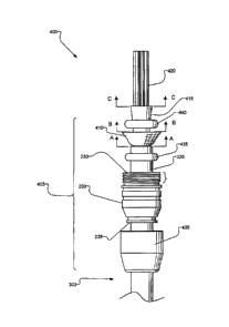
[0031] Referring now to figures 2-5, an exploded cable gland assembly view
(400) of a
conventional multi-strand electrical power cable (300) being assembled with a
cable
8
gland assembly (405) of the present invention is shown in Figure 4. In a first
assembly
step the cable gland housing (200) is installed over a terminal end of the
multi-strand
cable (300). The cable terminal end is inserted into the second circular
aperture (235) of
the cable gland housing (200) and extends through the first circular aperture
(230). An
outer molding (430), described below, may be installed over the cable terminal
end prior
to installing the cable gland housing (200) over the cable terminal end.
However, the
outer molding (430) is only shown separately in Figure 4 for clarity since the
outer
molding (430) is preferably molded onto the cable gland housing (200) either
prior to
assembling the cable gland housing (200) onto the multi-strand cable (300) or
after
assembling the cable gland housing (200) onto the cable.
[0032] In a second assembly step, the multi-strand cable (300) is prepared by
stripping
only the insulating cable sheath (320) from a terminal end thereof to expose
the
underlying cable shielding layer (315). In a non-limiting example embodiment,
a 2-5
inch length of only the cable sheath (320) is trimmed from the cable. The
arrows (A-A)
depict the location where the cable sheath (320) is removed to. In a second
step, a portion
of only the exposed cable shielding layer (315) is trimmed from the multi-
strand cable
(300) to expose the underlying outer strength member (310).
[0033] In various embodiments, the cable shielding layer (315) is formed by a
cylindrical
tube of braided metal such as braided copper, aluminum, tin, steel, brass,
bronze, silver,
or the like. The braided metals can be a composite metal structure such as tin
plated or
copper covered steel, copper plated with tin, or the like. The cable shielding
layer (315)
can also include composite shielding layers that combine non-conductive mono-
filanients,
or the like, interwoven with conductive metal strands. In further embodiments
the cable
shielding layer (315) may include two layers, such as an inner aluminum foil
layer, not
shown, surrounded by an outer braidcd metal layer such as braided tin plated
copper, or
the like. In any case the cable shielding layer (315) described herein
collectivity
describes single and double layer shielding layers, metal braided shielding,
non-braided
metal foil shielding, and composite shielding layers that include a
combination of highly
conductive, less conductive, and substantially non-conductive materials in
combination.
[0034] In a third step, the exposed cable shielding layer (315) is trimmed to
leave a
length of about 0.5-1.5 inch of the exposed cable shielding layer (315)
extending from the
cable sheath (320) as shown by arrows (B-B). In a fourth step, a portion of
only the
exposed outcr strength member (310) is trimmed from the cable to expose the
underlying
9
CA 2962049 2017-10-25
conductive strands (305) and any inner strength members (325) that may be
included. In
a non-limiting example embodiment, thc exposed outer strength member (310) is
trimmed
to leave about 0.5-1.5 inch of the exposed outer strength member (310)
extending from
the cable shielding layer (315) as shown by arrows (C-C). As will be
recognized by those
skilled in the art, the cable trimming steps two through four can be completed
before
installing the cable gland housing (200) and the outer molding (430) onto the
multi-strand
cable (300). In any event if the cable gland housing (200) and the outer
molding (430)
are not installed onto the multi-strand cable (300) terminal end they should
be installed
before the next step.
[0035] In a fifth step a_weather gaskct (435), such as an 0-ring, is assembled
onto the
multi-strand cable (300) over the cable sheath (320) between the end of the
cable sheath
(320) and the cable gland housing (200). In a sixth step, the exposed cable
shielding layer
(315) is flayed radially outward away from the outer strength member (310). In
a seventh
step, a cable shield pressure ring (440), such as an 0-ring, is installed onto
the terminal
end of the multi-strand cable (300) over the exposed outer strength member
(310).
[0036] Turning now to Figure 5, a final cable gland assembly (500) is shown
fully
assembled and mounted to a wall of thc enclosure housing (110) according to
the present
invention. The final cable gland assembly (500) shows the cable gland housing
(200)
attached to the enclosure housing (110) by threaded engagement between the
external
threads (240) formed on the housing interface end (220) of the cable gland
housing (200)
and a threaded housing aperture that passes through a sidewall of the
enclosure housing
(110). The final cable gland assembly (500) shows the outer molding (430)
installed over
the outside surface of the cable gland housing (200) covering the cable
interface end
(225). The final cable gland assembly (500) shows the terminal end of the
multi-strand
cable (300), i.e. the conductive strands (305) extending into the enclosure
housing with
the cable sheath (320) extending into the hollow cavity (210) formed by the
annular wall
(205) through the second aperture (235) and positioned with the cable sheath
trim line
(510) positioned about half way between the first circular aperture (230) and
the second
circular aperture (235). The final cable gland assembly (500).shows the
weather gasket
(435) engaged with an annular weather gasket groove (505) formed on an inside
surface
of the annular wall (205).
In an eighth assembly step the weather gasket (435) and multi-strand cable
(300) are
manipulated to engage the weather gasket (435) to seat with the annular
weather gasket
CA 2962049 2017-10-25
groove (505) while the weather gasket is surrounding the cable sheath (320).
In the
seated position, the weather gasket (435) is compressed against the cable
sheath (320).
More specifically an inside diameter of the weather gasket (435) is sized to
substantially
match or to be formed slightly smaller than an outside diameter of the cable
sheath (320).
Additionally an outside diameter of the annular weather gasket groove (505) is
formed
slightly smaller than an outside diameter of the weather gasket (435) such
that when the
weather gasket is engaged with the annular weather gasket groove (505) while
the
weather gasket is surrounding the cable sheath (320) the weather gasket is in
compression
and applies a radially inwardly directed compression force against the cable
sheath.
Additionally a longitudinal position of the multi-strand cable (300) is
adjusted to position
the cable sheath trim line (510) about half way between the first circular
aperture (230)
and the second circular aperture (235).
[0037] In a ninth assembly step a first environmental molding material (515)
is injected
into the hollow cavity of (200) to substantially fill an annular space
surrounding the cable
sheath (320) wherein the annular space extends longitudinally between the
weather gasket
(435) and the cable sheath trim line (510). The first environmental molding
material
(515) is poured as a liquid and then hardens or cures in place. The first
environmental
molding material (515) preferably bonds to the cable sheath (320) and inside
surfaces of
the annular wall (205) and to the weather gasket (435) to hold the weather
gasket and
multi-strand cable (300) is place and to provide a substantially gas and
liquid tight barrier
between the second aperture (235) and the surrounding ambient environment.
[0038] In a non-limiting embodimcnt, the weather gasket (435) is formed from a
compressible polymer material such as an ethylene propylene diene monomer
(EDPM)
rubber, which can have a modulus of elasticity of about 0.75 to 1.25 MPa
depending on
formulation. The first environmental molding material (515) comprises a liquid
sealant in
an uncured state that is flowable into the sealing volume described above.
Suitable liquid
sealants include a low viscosity curable epoxy such as such a Resinlab EP
1282, which is
a two-part encapsulant epoxy with a mixed viscosity of 3000cps.
[0039] In a tenth assembly step, the exposed portion of cable shielding layer
(315) is
flayed radially outward and the cable shield pressure ring (440) is installed
over the outer
strength member and under the flayed out cable shielding layer (315) in a
manner that
causes the cable shielding layer (315) to become forced into mating contact
with an inside
surface of the annular wall (205) substantially around the entire
circumference thereof. In
11
CA 2962049 2017-10-25
particular the cable shield pressure ring (440) is longitudinally positioned
to engage with
an annular pressure ring groove (520) sized and properly shaped to engage with
the cable
shield pressure ring (440).
[0040] Prior to final assembly, the annular pressure ring groove (520) is
optionally coated
with an electrically conductive paste such as a conductive silver paste, which
has a
resistivity of about 1.0x10⁻⁸to 3.0x10⁻⁸ Ohm-m. In the present, non-limiting
embodiment,
thc cable shield pressure ring (440) comprises a non-electrically conductive 0-
ring that is
formed from a compressible polymer material such as an ethylene propylene
diene
monomer (EDPM) rubber, with modulus of elasticity of about 0.75 to 1.25 MPa.
The
cable shield pressure ring (440) is selected with an outer diameter over-sized
relative to
the largest outside diameter of the annular pressure ring groove (520).
Accordingly,
when the cable shield pressure ring (440) is engaged with the annular pressure
ring
groove (520), an expansion force directed substantially radially out from a
center axis of
the cable shield pressure ring (440) is generated by compressing the cable
shield pressure
ring (440) which tends to force the cable shielding layer (315) into mating
contact with
the inside surface of the annular wall (205) and provides an electrically
conductive path
that extends from the cable shielding layer (315) to the annular wall (205)
and then to the
enclosure housing (110) through the threaded engagement (240) at the housing
interface
end (220) with a threaded aperture that passes through the enclosure wall
(110). In the
present, non-limiting embodiment, cable shield pressure ring (440) comprises
an 0-ring
having a circular cross sectional shape; however, other mechanical elements
such as a
metal spring, or the like, may be used to apply the desired outward radial
expansion force
to hold the cable shielding layer (315) in electrical contact with the annular
wall (205)
without deviating from the present invention. It is further noted that the
above described
assembly technique and elements substantially enclose the conductive strands
(305)
within a Faraday Cage comprising the cable shielding layer (315), the cable
gland
housing (200) and the external connector (120).
[0041] In an eleventh assembly step, the outer strength member (310) is flayed
out or
unwoven to expose individual threads or fibers surrounding the conductive
stands (305).
Additionally, if an inner strength member (325) is present, the inner strength
member
(325) is flayed out or unwoven to expose individual threads or fibers thereof
Both of the
strength members may extend through the first circular aperture (230) during
initial
assembly and held in place for the next step.
12
=
CA 2962049 2017-10-25
[0042] In a twelfth step, a liquid sealant such as a low viscosity curable
epoxy is injected
into the hollow cavity (210) and is cured to form a second environmental
molding (525).
The liquid sealant can comprise any suitable bonding or potting material that
is flowable
in an uncured state, e.g., with a viscosity of 3000cps or less, to fill void
spaces within
hollow cavity (210) to at least partially surround the flayed out cable
shielding layer
(315), the cable shield pressure ring (440), the inner strength member (325)
and outer
strength member (310). The cured sealant fixes in place and preferably bonds
to threads
or fibers of the inner strength member (325), threads and fibers of the outer
strength
member (310) and to surfaces of the cable shield pressure ring (440), the
cable shielding
layer (315), and the inside surface of the annular wall (205). In a non-
limiting
embodiment, the cured sealant is a two part encapsulant epoxy such as
Resinlabs EP1282
that has tensile yield strength of at least 800 PSI when cured. In a non-
limiting
embodiment, fibers comprising inner and outer strength members (325) and (310)
are
separated from each other and soaked with the curable liquid sealant prior to
injecting the
sealant into inner cavity (210).
[0043] The outer molding (430) is formed to fit over a contour of the cable
interface end
(225) of the cable gland housing (200). The outer molding (430) comprises a
material
suitable thr low pressure molding, which is tough when cured and has a fast
cure time
such as a polyurethane or a thermoplastic polyamid. The outer molding (430)
can be
formed with polyurethane, thermoplastic polyamides including Macromelt 6208
(manufactured by Henkel AG & Company), and other suitable polyvinyl chlorides,
nylons or other thermoplastic or thermoset materials. In the present, non-
limiting,
embodiment outer molding (460) is formed by an insert molding or over molding
process
wherein uncured material comprising outer molding (460) flows into and fills
annular
grooves or channels (530) formed on the outer circumferential surface of the
on annular
wall (205). Preferably, each annular groove (530) extends completely around
the outer
circumferential surface of the annular wall (205). When cured, the interface
of outer
molding (430) with the annular grooves (530) increases grip and retention
strength of
outer molding (430) on the cable gland housing (200) to thereby increase a
pull out
strength of the multi-strand cable (300) with respect to the cable gland
housing (200). In
an alternate embodiment, outer molding (430) can be formed in a separate
manufacturing
step and assembled onto the cable gland housing (200). As is further shown in
Figure 5,
the outer modeling (430) preferably fits tightly to the cable sheath (320)
around its entire
13
CA 2962049 2017-10-25
CA 2962049 2017-03-22
circumference at the cable to outer molding interface (535). Additionally, the
outer
molding (430) preferably fits tightly against the enclosure wall (110) at the
enclosure wall
to outer molding interface (540). Additionally a bead of weather sealant e.g.
silicon
caulking or the like, can be applied at the outer molding interface (540) to
further weather
seal the interface.
[0044] Bonding between the second environmental molding (525) and one or more
of
inner strength member (325) and outer strength member (310) increases the
amount of
force required to dislodge the multi-strand cable (300) from the cable gland
housing
(200).
[0045] After completion of the cable gland assembly (405), the cable gland
assembly is
installed onto the enclosure housing (110) e.g. after the bead of weather
sealant is applied
at the outer molding interface (540). Thereafter the conductive strands (305)
may be
terminated as needed inside the enclosure before closing the enclosure. In use
the
external electrical connector (120) is connected to an external device, not
shown, to
exchange power and communication signals between the connected external device
and
whatever electrical device is operating inside the enclosure housing (110).
[0046] Referring now to Figures 2 and 5 the housing interface end (220) of the
cable
gland housing (200) includes external threads (240) and a shoulder (245)
provided to
interface with mating internal threads of an aperture passing through a wall
of the device
enclosure (110). In this embodiment, it is possible to remove the cable gland
assembly
from the enclosure by disengaging the threaded cable gland housing (200) from
the
enclosure wall (110) even if the threads have been sealed by a weather sealant
or secured
by a breakable adhesive bond. However other more permanent attaching methods
may
be preferable in some applications that do not include threaded engagement but
instead
may rely on a more permanent attachment such as using a pressure or
interference fit,
brazing or soldering, or more resilient adhesive bond. Additionally the
conducting
strands (305) may include a plurality of individually insulated electrically
conductive
wires, one or more twisted wire pairs, or the like.
[0047] It will also be recognized by those skilled in the art that, while the
invention has
been described above in terms of preferred embodiments, it is not limited
thereto. Various features and aspects of the above described invention may be
used
individually or jointly. Further, although the invention has been described in
the context
of its implementation in a particular environment, and for particular
applications (e.g. for
14
CA 2962049 2017-03-22
DC power systems), those skilled in the art will recognize that its usefulness
is not limited
thereto and that the present invention can be beneficially utilized in any
number of
environments and implementations where it is desirable to provide a weather
proof cable
interface with an enclosure wall that includes forcing a cable shielding layer
into mating
contact with a connector housing. Accordingly, the claims set forth below
should be
construed in view of the full breadth and spirit of the invention as disclosed
herein.